HAL Id: hal-00563626
https://hal.archives-ouvertes.fr/hal-00563626
Submitted on 7 Feb 2011
HAL is a multi-disciplinary open access
archive for the deposit and dissemination of
sci-entific research documents, whether they are
pub-lished or not. The documents may come from
teaching and research institutions in France or
abroad, or from public or private research centers.
L’archive ouverte pluridisciplinaire HAL, est
destinée au dépôt et à la diffusion de documents
scientifiques de niveau recherche, publiés ou non,
émanant des établissements d’enseignement et de
recherche français ou étrangers, des laboratoires
publics ou privés.
Automating UML Models Merge for Web Services
Testing
Vincent Pretre, Fabrice Bouquet, Christophe Lang
To cite this version:
Vincent Pretre, Fabrice Bouquet, Christophe Lang. Automating UML Models Merge for Web Services
Testing. iiWAS’08, 10th int. Conf. on Information Integration and Web-based Applications and
Services, 2008, Austria. pp.55–62. �hal-00563626�
Automating UML Models Merge for
Web Services Testing
Vincent Pretre
Fabrice Bouquet
Christophe Lang
Frédéric Dadeau
Adrien de Kermadec
Laboratoire d’Informatique de Franche-Comté 16 route de Gray
25030 Besancon CEDEX
[email protected]
ABSTRACT
This paper presents a method for merging UML models which takes place in a quality evaluation framework for Web Services (WS). This framework, called iTac-QoS, is an ex-tended UDDI server (a yellow pages system dedicated to WS), using model based testing to assess quality. WS ven-dors have to create UML model of their product and our framework extracts tests from it. Depending on the results of the test execution, a mark is given to WS. This mark per-mits to customers to have an idea about the quality of WS they find on our UDDI server.
Up today, our framework was limited to WS which did not use other WS. This was justified by the fact that it is im-possible for vendors to create a good model of a foreign product. Our method for model merging solves this prob-lem: each vendor produces models of its own product, and we automatically merge the different models. The resulting model from this merging represents the composition of the different WS.
For each type of diagram present in the models (class, instance or state-chart diagram), a method is proposed in order to produce a unique model. In addition to this, a solu-tion is proposed to merge all OCL code in the class modeling the WS under test. Unfortunately, this process introduces inconsistencies in the resulting model, that falsify the results of the subsequent test generation phase. We thus propose to detect such inconsistencies in order to distinguish incon-sistent and unreachable test targets.
Keywords
Web services, UML, model based testing, consistency
1.
EVALUATION OF WEB SERVICES
Since few years, Service Oriented Architecture takes an
Permission to make digital or hard copies of all or part of this work for personal or classroom use is granted without fee provided that copies are not made or distributed for profit or commercial advantage and that copies bear this notice and the full citation on the first page. To copy otherwise, to republish, to post on servers or to redistribute to lists, requires prior specific permission and/or a fee.
iiWAS2008 November 24-28, 2008, Linz, Austria.
Copyright 2008 ACM 978-1-60558-349-5/08/0011 ...$5.00.
important place in software development. Web Services (WS) are used in many kinds of applications: web sites, widgets or more classical software. This omnipresence leads to a need of validation.
That need led us to create a quality evaluation framework for WS. Until now, this framework was not able to test WS working with other WS. This paper introduces a method for model merging, which solves this lack.
The first section introduces context which led us to pro-pose a model merging solution. First, we introduce WS and our vision of their quality. Then, we present iTac-QoS, our validation framework for WS. The merging method pro-posed in this paper takes place in this framework. At last, we present why model merging is a necessity for testing a particular type of web services.
Second section is dedicated to related works. It is split in three parts: UML modeling of WS, test of WS and model merging. The third section introduces our method to auto-matically merge UML models, applied on an example. Then, the fourth section presents how to detect and solve the inconsistency problems resulting from the model merg-ing process.
At last, we conclude and introduce future work.
1.1
Web services quality
We define WS as the server part of a client-server applica-tion in which exchanged messages are written in XML [25]. Generally, WS are built upon SOAP (Simple Object Access Protocol [15]). This protocol defines structure of XML mes-sages, and uses well known protocol such as http or smtp. The first advantage of WS is their compliance with most security policies, which generally authorize http and smtp protocols. Moreover these protocols and XML bring the sec-ond main advantage of WS: portability. Almost every pro-gramming language has libraries handling XML and those protocols. This makes it possible to easily create clients for a web service in any programming language.
Writing a client for a WS can be easily done using a WSDL (Web Service Description Language [8]) file. This file de-scribes everything required to communicate with a WS: ad-dress, provided operations, message format, exchange pro-tocols . . . A second technology related to WSDL is UDDI (Universal Description Discovery and Integration [19]). A UDDI server is a yellow pages system for WS. It permits customers to easily find WS, and vendors to spread their
Vendor
1 - Deployment 2 - Test model production
3 - Registration Web service UDDI server 4.1 - Tasks on model 4.2 - Model merging 4.3 - Tests generation 5 - Tests execution Customer 6 - Search services 7 - Services evaluation
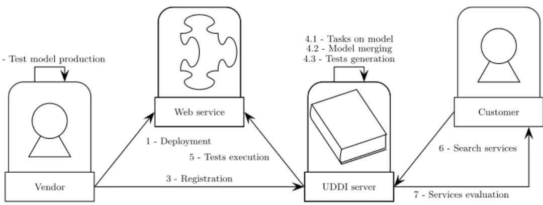
Figure 1: From Web service deployment to quality assessment
products. We are currently working on an improvement of UDDI, in which the server provides more than the informa-tion given in the WSDL files, it also assesses the quality of results produced by WS.
There exists many criteria to describe quality of a WS: ac-cessibility, time needed to compute a result, privacy of data and customer, quality of results . . . We consider two criteria to define quality of a WS. The first one is results correctness (is the answer given fits with the expected one ?) and the second one is result completeness (if many answers can be given, are they all provided ?).
There is many reasons that can lead to quality leak of a WS. We can classify them in two categories: static or dynamic. Classification is based on reproducibility of quality leak. Re-producible problems are considered as static, the others as dynamic.
For WS, the most obvious dynamic problem is network: packets may be lost during transport, leading to a corrupted message. As this kind of problem is not reproducible, it is quite impossible to certify that a WS is free of them. There exists few static reasons for quality leak. The first one is, obviously, bugs introduced during the development phase. The second one is software on which the WS relies: web server, libraries, other applications, etc. Bugs may exist in those software, and have an impact on WS quality. The last reason is the interaction relations between WS opera-tions.
There exists two kinds of relations between WS opera-tions. The first kind of relation is composition. An infor-mal definition of composition is “a WS operation acting as a client of another operation”. There exists several composi-tions. We consider three criteria to discriminate them: syn-chronicity (a composition is synchronous when the com-posing operation uses results of the composed operation), dynamicity(a composition is dynamic when the composed operation has been found through a UDDI server) and dis-tributivity(a composition is distributed when the two in-volved operations do not belong to the same WS). Due to fault propagation, synchronous compositions have an impact on quality. If an operation bases its results on wrong data, it may be false.
The second kind of relation is the temporal dependency. Its informal definition is “operation a temporally depends on the operation b if it can be called only if b has been called
previously”. Generally, this dependency is due to shared data, on the server side (operation b writes in a database, operation a reads what has been written) or on the client side (operation b produces a list of results, the client picks up one and uses it as a parameter of a). As for composition, temporal dependency can be responsible of fault propaga-tion.
Thus, as we see in this part, there are numerous possible quality leaks in WS. This is why we set up iTac-QoS, a quality evaluation framework for WS.
1.2
iTac-QoS: using tests to asses quality
iTac-QoS (iTac Tests And Certifies Quality of Services [20]) is a quality evaluation framework for WS. It relies on a UDDI server, and provides quality information based on tests. Fig-ure 1 shows the evaluation process, that we now describe. First, the WS vendor deploys its product (1), and creates a model for test (2). When he registers its product on our framework (3), provides classical information (WSDL file, description . . . ) and this model. Before test production, the framework has to perform some tasks on the model (4.1) such as interaction discovery, or string replacement. If dis-tributed compositions have been discovered, models of the different WS need to be merged (4.2). Then, tests are gen-erated using Test Designer (TD) a commercial tool from the Smartesting company1
. (4.3) and executed (5). Result of these tests are used to compute a mark for each WS opera-tion.
When a customer searches WS on the UDDI server (6), it provides the list of corresponding WS and the mark they obtained (7). This mark helps customers to have an idea of the quality of WS found.
This paper focuses on step 4.2. In order to make our method for model merging easier to understand, we will de-tail two important steps of the assessment process: modeling and test generation.
The modeling solution chosen was UML, because of its ex-tensibility and reputation. WS vendors are more likely to know UML than any other modeling language.
UML models required by our framework contain three types of diagrams (class diagram, instance diagram and state-chart diagram), completed by OCL code. Those models have to be compliant for the test generation tool we con-1
sider, Test Designer (TD), as described in [6].
The first type of diagram is class diagram. Class diagram is mandatory for two different parts of the WS: interface and data used. The interface part is composed of a class representing the WS and a set of class describing exchanged messages. This part of the class diagram is needed to pro-duce suitable test scripts (in which messages content is set before operation call). The second part of diagram class is more classical, and represents data used by the WS (for ex-ample, a model describing an online store WS will contain classes “customer”, “commands”, “products” . . . ).
For each operation described in the class diagram, post-conditions must be expressed using OCL. They describe how the model changes when the operation has been called. We do not use pre-condition (meaning that the pre-condition is always true). Our model is built upon the defensive paradigm: error cases have to be handled in post-conditions and return error codes. We chose this solution in order to be able to capture all the possible behaviors of the WS under test.
The second diagram of our model is an instance diagram. When the class diagram gives structure of data, instance diagram gives value to them. This diagram has to present real data, because our framework is fully automatic, and no-body will translate abstract data into real data. All classes declared in the model must have at least one instance in the instance diagram. It is useless to represent all data used by the WS in the instance diagram. The modeler has to choose a subset of data and integrate them in the model. Data cho-sen must be as reprecho-sentative as possible. For example, if the modeled WS handles multiple level of users, the model must contain at least one user of each level (such as admin, member, guest, etc.).
The last kind of diagram is state-chart diagram. Its goal is to model the life-cycle of the web service. This is not a mandatory diagram, but it helps test generation by describ-ing how WS has to be used. If such a diagram is made, it must represent all possibilities of WS utilization.
Figure 2 synthesizes how a WS is decomposed in its model. We then use Test Designer (TD) to generate tests. First, it extracts every behavior described in the model. A be-haviorcan be seen as a path in the control-flow graph of an operation written in OCL (for example, an “if” statement may create two behaviors: one when its condition is satisfied and one when it is not). Behaviors may also be extracted from a state-chart diagram (when a state is reached). All those behaviors are called test targets. For each one, TD generates a sequence of operations that aims at activat-ing it. This sequence is called a test.
Web service
Class diagram Interface and structure
OCL code Behavior Instance diagram Data values State-chart diagram Temporal evolution
Figure 2: An overview of model’s structure
An oracle is associated to each test. It is given by the state of the model after test execution and/or the values returned by the last operation call. In our framework, we only con-sider the latter option: if the results produced by the last operation of the test are not the expected one, the test fails. Now, we present limits of this modeling solution and why it is not adapted for WS composition testing.
1.3
The necessity of model merging
The need for model merging only occurs when a WS uses other WS. To test such a WS, there are two solutions. In the first one, the vendor of the WS produces a model describ-ing the two WS involved in the composition. The second solution is that each vendor models its own product, and our framework merges these two models. The result of this merging is a new model which described the composition of the two WS.
We consider that the first approach is not viable, since a vendor may not be able to produce a valid model of a for-eign product. A “login” operation seems simple to model: if there exists a user corresponding to login and password given in parameter, he is logged in the system. If there is no such user, an error is raised.
This solution would certainly fit in most cases. But if the WS has more severe security policies, tests may fail because the model does not match with implementation. For exam-ple, composed WS security policies specify that a customer can not be logged in twice in the same time. If our frame-work is not aware of this, it will try to run parallel tests to accelerate quality evaluation process, and tests will fail. Security policies are one of the reasons why model of the composed WS must concord to its behavior. A simple cus-tomer is aware of how the composed WS reacts in normal conditions of use, but may not precisely know all security policies. For this reason, he is not able to produce a efficient model for this WS.
A second problem of modeling a foreign WS is creation of instance diagram. As we said before, this diagram must rep-resent real data. Someone modeling a foreign WS may not know which data it uses, and so may be unable to produce a useful instance diagram. As we explained before, the in-stance diagram has to be representative of the system. If data is missing, the testing tool may not be able to produce some tests.
A solution could be to get model given by the vendor when he registered his WS. As we saw before, this model contains real data that may be critical. For this reason, models can not be shared. Thus, this solution can not be used. Those two reasons led us to choose the solution of model merging. Before introducing our method, we present works about WS testing and model merging.
2.
RELATED WORKS
In order to propose an efficient solution for model merg-ing, we had to look at existent solutions. This section is di-vided in three parts. First, we introduce works using UML to model compositions. Then, we take a look at works us-ing UML to test WS, and how they handle compositions. Finally, we present works about merging UML models.
2.1
UML for modeling web services and
com-positions
UML-WSC is an UML extension introduced in [24]. It is presented as an alternative for BPEL2
. Another solution for composition modeling has been introduced in [1]. This paper presents design patterns to easily design compositions with UML.
We think that these works are not relevant for our purpose. The first reason is that those models are not designed for test production. The second one is that these models rep-resent the whole composition. We explained before why we do not think that this kind of method is suitable for our framework.
UML modeling for WS was also presented in [18]. This modeling solution is not suitable for test generation, be-cause behavior of WS is not modeled. A link between UML meta-models and WS standards (WSDL, BPEL) is shown in [23].
2.2
Testing web services with UML
The choice of UML for test generation can be criticized, because of its lack of formalism. For example in [17], UML has been set aside because authors considered that UML could not describe precisely evolution of a WS. Our model-ing solution does not suffer from this lack of formalism, as it has been shown in [6].
There also exists works that deal with UML modeling for WS testing. Some does not take composition into account, such as [14]. The others deal with composition in different ways. In [16], when the WS under test performs a composi-tion, it does not really communicate with another WS. The test driver emulates the composed WS. In [2], a proxy is set up between WS under test and composed WS. That allows to verify how the WS under test acts toward composed WS. In [13], UML is combined with BPEL in order to verify if composition workflow is respected.
Those solutions are really efficient for composition testing, but do not provide clues to our main problem: how to easily make a model of the composition compliant with our test tool?
According to our knowledge, there is no solutions dealing with model merging to handle WS testing. To propose a solution, we had to investigate on works about model merg-ing.
2.3
Model merging
Composition is not a specificity of WS. Since a few years, different solutions have been proposed for creating applica-tions from components. Having models to represent those compositions is one goal of [3]. This paper does not show solutions for model merging, but deals with the use of meta-models to handle several kinds of components (EJB, Corba . . . ).
In [12], a UML profile is proposed in order to help model compositions. No explanations are given on how to produce an unique model from different models using this profile.
A model merging solution is introduced in [9]. This method 2
Business Process Execution Language - A language used to model compositions
aims at helping subject-oriented design. An application is not designed in a big model, but by a set of small models. Each one of those models describes a subject of the applica-tion. The method proposed in this paper may not be applied to WS model merging, because composition description re-quires both models. In [4], another model merging solution is proposed. This solution only applies a merging for dia-gram classes, and do not take into account other types of diagram.
We present now our own solution for model merging.
3.
MERGING UML MODELS
We saw that model merging is necessary to test a WS per-forming distributed compositions. In order to illustrate our method for model merging, we introduce an example. This example is composed of two WS. The first one is an online store WS, which composes a parcel service WS. The online store WS provides operations: register, login, lo-gout, search, addToCart and validate. The parcel service WS provides three operations: login, getPrice and logout. We now present our method for model merging, which is done in four steps: the first one is to transform state-charts into OCL code. The second one consists in merging the different class diagrams. Then, OCL code of classes are merged in class modeling the WS under test. Eventually, instance diagram are also merged to produce the final model.
3.1
State-chart
There would be two solutions to produce a final model in which specifications of the several state-charts are captured. The first one would be to produce a final state-chart that is a combination of the different one.
The second solution would be to translate the state-charts of composed web services into OCL code, and the state-chart of the composing web services is kept in its original version. With the first solution, the final state-chart models tem-poral evolution of every WS involved in the composition. With the second one, the state-chart only models evolution of the WS under test.
This is why we chose this solution.
The first step in the transformation of the state-chart in OCL is to create a new enumeration (“state-List”), which lists all states described in the state-chart, including initial and final state. A new attribute (“state”) is added to the class describing the web service, which has for type the enu-meration previously created.
Then, for each operation, we list all transitions using it as a trigger. These transitions are noted as 4-tuple, in the form {lS, g, rS, op}, where “lS” is state leaved by the transition, “g” the guard of the transition, “rS” the state reached by the transition and “op” operation that may be automatically ac-tivated when “rS” is reached.
This list is the base for OCL update, which permits simula-tion of the state-chart.
Update of OCL code is done in two steps. First, we in-clude all the OCL code of the operation in a “if” statement. Its condition is “(((self.state = lS1) and (g1)) or ((self.state = lS2) and (g2)) or . . . or ((self.state = lSn) and (gn)))”. Thanks to this condition, the operation has effects only if it
OnlineStore . . . Customer name ParcelService login() getPrice() logout() ParcelService currentUser login() getPrice() logout() Customer login OnlineStore . . . 1-Customer name ParcelService currentUser login() getPrice() logout() 2-Customer login
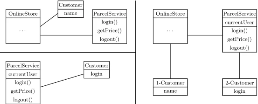
Figure 3: Example of class diagram merge
is called in a case that has been specified in the state-chart diagram.
Then we simulate the evolution in the state-chart diagram. To do this, at the end of OCL code (just before closing the “if” statement previously created), we create a list of “if” statement that make the “state” attribute’s value change. They look like this following code:
i f ( ( s e l f . s t a t e = l S 1 ) and ( g1 ) ) then s e l f . s t a t e = r S 1 and s e l f . op1 ( ) e l s e i f ( ( s e l f . s t a t e = l S 2 ) and ( g2 ) ) then s e l f . s t a t e = r S 2 and s e l f . op2 ( ) e l s e . . . i f ( ( s e l f . s t a t e = l S n ) and ( gn ) ) then s e l f . s t a t e = r S n and s e l f . opn ( ) e n d i f . . . e n d i f e n d i f
There is a particular case when the reached state is a choice point. In this case, we can not write “self.state = . . . ”. Each transition is transformed into imbricated “if” statements (where the guard of the transition becomes the condition of the “if” statement). The order in transformation as no importance, except if a guard of one of these transition is “[else]”. In this case, the state reached by this transition is used to produce the “else” case of the last “if” statement. The code produced by this transformation is shown in code below: i f ( g1 ) then s e l f . s t a t e = r S 1 and s e l f . op1 ( ) e l s e i f ( g2 ) then s e l f . s t a t e = r S 2 and s e l f . opn ( ) e l s e . . . i f ( gn ) then s e l f . s t a t e = r S n and s e l f . opn ( ) e l s e /∗ i f t h e r e i s a n ‘ ‘ [ e l s e ] ’ ’ g u a r d ∗ /
s e l f . s t a t e = r S else and s e l f . opelse ( ) e n d i f
. . . e n d i f e n d i f
Once all operations are treated, there is one step left be-fore state-chart diagram destruction. In some cases, opera-tion may use the “OCLisInState(x)” keyword (that permits to know the current state of the system). We replace all these use by “self.state = xS” (where “xS” is the enumerate value corresponding to the state “x”).
Now the state-chart diagram can be deleted, because it do not have any interest anymore. The next step in model merging is about the class diagram.
3.2
Class diagram
Class diagram merging is a quite simple step: all classes of the models have to be merged into a single class dia-gram. The main problem is aliasing: if two classes have the same name, do they represent the same thing? Obviously, we can not trust classes names. Two classes named “cus-tomer” in two models of two different WS will not represent the same customers. But two classes named “getParcelPri-ceInputMsg” will represent the SOAP message used as input parameter for the getparcelPrice operation.
In order to discriminate classes modeling the only thing shared by the two model (SOAP messages and interfaces of WS), we will use WSDL files. As explained before, those files describe messages used to communicate with a WS. So we use this files to discover which classes models shared messages. All other classes are renamed before merging. To rename classes, we give a number to each model. Then, for each class which do not represent a shared message, we pre-fix its name with the number given to the model it belongs to.
Once renaming done, all classes are sent into a new class diagram.
It is possible that shared messages are not represented ex-actly the same way. In this case, we keep all attributes and operations from the several classes modeling those data and include them in a single class.
Figure 3 shows merging process on a sub-part of our ex-ample. For space reasons, we simplified the diagram (for example, cardinality, name and role of association are re-moved). Up left part represents a sub-part from the online store model, below is shown a sub-part from the parcel ser-vice model. The right side is what is obtained when merging these two sub-parts.
Once this step is finished, we can merge all OCL code into the class modeling the web service under test.
3.3
OCL
We propose a solution for OCL merging because our test tool (TD) does not handle operation call. That means that the whole OCL code must be contained in the class repre-senting the web service under test.
This merging solution is only possible because TD under-stands OCL code as a sequential language, not as a paral-lel language. If we write “self.attr = 2 and self.attr = 4”, this should be evaluated as false, because, in the same time,
“attr” should have for value 2 and 4. For our test tool, this means “attr has for value 2, then it has for value 4”. This solution does not comply with OCL specifications (in which OCL is an constraint language, not an action lan-guage). This solution has been chosen during TD design to help model design: most people know how to use action language, and some operations could not be written with parallel interpretation of OCL.
Merging OCL code is done in two phases: the first one is the references update. In OCL code, there may be many references (to an attribute of the class, to another class . . . ), that are linked to a context. For example, the op-eration “login” of the class “parcelService” has for postcon-dition “self.user = pUser”. The context is the operation “lo-gin”, so “self.user” refers to the attribute “user” of the class “parcelService”.
In order to move all OCL code in the class representing the web service under test, we have to change all those refer-ences to adapt them to their new context. This is done by changing the “self” keyword by the path linking new context to old context. In the previous example, the code will be moved to the class “onlineStore”. The classes “onlineStore” and “parcelService” are linked by the association “uses”, the role on the “parcelService” class side is “parcelWS”. When OCL code of the operations of the “parcelService” class is moved to the operations of “onlineStore”, all references to “self” will be changed to “self.parcelWS”.
We also have to update a second kind of references: oper-ation’s parameters. All references to parameters must be changed by the value assigned at the call.
Once this is done, OCL code of an operation is moved before its call. The next step is to link results produced by operation to call of the operation. There is two possibili-ties here. The first one occurs when “result” is only affected once. In this case, this affectation is deleted, and the call to the operation is replaced by the value used to instantiate “result”.
In the second case, “result” has multiple affectation. Here, we create a new attribute in the class under test, having the same type than the result. Each occurrence of result will be replaced by this attribute, and the call to the operation will also be replaced by this attribute.
Code below shows evolution of code in our example. We chose composition of operation login(user, passwd) from the parcel WS by operation validate from online store WS. In order to make the example more readable, we had to sim-plify the code (we do not use classes defining SOAP mes-sages). /∗− ORIGINAL CODE −∗/ /∗ O p e r a t i o n : v a l i d a t e ∗ / i f ( s e l f . p a r c e l S e r v i c e . l o g i n (” l o g i n ”, ” p a s s w o r d ”= ” o k ”) then /∗ b u s i n e s s c o d e , u s e l e s s f o r t h e e x a m p l e ∗ / e n d i f /∗ O p e r a t i o n : l o g i n ( u s e r , p a s s w d ) ∗ / i f ( s e l f . u s e r s −>e x i s t s ( u | u . l o g i n = u s e r and u . p a s s w o r d = pas s w d ) then s e l f . c u r r e n t U s e r = s e l f . u s e r s −>any ( u | u . l o g i n = u s e r and u . p a s s w o r d = pas s w d ) and r e s u l t = ” o k ” e l s e r e s u l t = ” A u t h e n t i c a t i o n f a i l e d ” e n d i f /∗− 1 − REFERENCES UPDATE −∗/ /∗ O p e r a t i o n : l o g i n ( u s e r , p a s s w d ) E v e r y r e f e r e n c e t o s e l f i s c h a n g e d t o s e l f . p a r c e l S e r v i c e ∗ / i f ( s e l f . p a r c e l S e r v i c e . u s e r s −>e x i s t s ( u | u . l o g i n = u s e r and u . p a s s w o r d = pas s w d ) then s e l f . p a r c e l S e r v i c e . c u r r e n t U s e r =
s e l f . p a r c e l S e r v i c e . u s e r s −>any ( u | u . l o g i n = u s e r and u . p a s s w o r d = pas s w d ) and r e s u l t = ” o k ” e l s e r e s u l t = ” A u t h e n t i c a t i o n f a i l e d ” e n d i f /∗− 2 − PARAMETERS UPDATE −∗/ /∗ O p e r a t i o n : l o g i n ( u s e r , p a s s w d ) R e f e r e n c e s t o p a r a m e t e r u s e r a r e c h a n g e d b y i t s v a l u e ” l o g i n ” , a n d t h o s e t o p a r a m e t e r p a s s w d t o ” p a s s w o r d ” ∗ / i f ( s e l f . p a r c e l S e r v i c e . u s e r s −>e x i s t s ( u | u . l o g i n = ” l o g i n ” and u . p a s s w o r d = ” p a s s w o r d ”) then s e l f . p a r c e l S e r v i c e . c u r r e n t U s e r = s e l f . p a r c e l S e r v i c e . u s e r s −>any ( u | u . l o g i n = ” l o g i n ” and u . p a s s w o r d = ” p a s s w o r d ”) and r e s u l t = ” o k ” e l s e r e s u l t = ” A u t h e n t i c a t i o n f a i l e d ” e n d i f /∗− 3 − CODE MERGING −∗/ /∗ O p e r a t i o n : v a l i d a t e ( ) A l l c o d e f r o m o p e r a t i o n l o g i n ( ) i s b r o u g h t b e f o r e i t s c a l l i n o p e r a t i o n v a l i d a t e ( ) ∗ / i f ( s e l f . p a r c e l S e r v i c e . u s e r s −>e x i s t s ( u | u . l o g i n = ” l o g i n ” and u . p a s s w o r d = ” p a s s w o r d ”) then s e l f . p a r c e l S e r v i c e . c u r r e n t U s e r = s e l f . p a r c e l S e r v i c e . u s e r s −>any ( u | u . l o g i n = ” l o g i n ” and u . p a s s w o r d = ” p a s s w o r d ”) and r e s u l t = ” o k ” e l s e r e s u l t = ” A u t h e n t i c a t i o n f a i l e d ” e n d i f and i f ( s e l f . p a r c e l S e r v i c e . l o g i n (” l o g i n ”, ” p a s s w o r d ” = ” o k ”) then /∗ b u s i n e s s c o d e , u s e l e s s f o r t h e e x a m p l e ∗ / e n d i f
/∗− 4 − MATCHING RESULT AND CALL −∗/
/∗ O p e r a t i o n : v a l i d a t e ( ) A n e w a t t r i b u t e , c a l l e d ” t m p L o g i n ” , i s c r e a t e d i n t h e c l a s s m o d e l i n g t h e o n l i n e s t o r e WS . R e f e r e n c e s t o r e s u l t c o m i n g f r o m l o g i n ( ) c o d e a r e r e p l a c e d b y t h i s a t t r i b u t e . T h e s a m e t h i n g i s d o n e f o r t h e c a l l t o t h e o p e r a t i o n . ∗ / i f ( s e l f . p a r c e l S e r v i c e . u s e r s −>e x i s t s ( u | u . l o g i n = ” l o g i n ” and u . p a s s w o r d = ” p a s s w o r d ”) then s e l f . p a r c e l S e r v i c e . c u r r e n t U s e r = s e l f . p a r c e l S e r v i c e . u s e r s −>any ( u | u . l o g i n = ” l o g i n ” and u . p a s s w o r d = ” p a s s w o r d ”) and s e l f . tm pLogi n = ” o k ” e l s e s e l f . tm pLogi n = ” A u t h e n t i c a t i o n f a i l e d ” e n d i f and i f ( s e l f . tm pLogi n = ” o k ”) then /∗ b u s i n e s s c o d e , u s e l e s s f o r t h e e x a m p l e ∗ / e n d i f
3.4
Instance diagram
Initial state merging is done by bringing all instances of class provided in the different models into a single instance diagram. As in class diagram merging, we have to change names in order to avoid conflicts between names. The same principles than in class renaming is applied, all names are prefixed by the number previously given to the model. As classes names have been changed, we must tell to instances the new names of the class they instantiate. Then, we can move all instances to a single instance diagram.
Now, we have to correct impacts of class diagram update on instances. The first action is to locate classes that re-ceived new attributes during class diagram merging. For all instances of those classes, we have to instantiate every attribute to its default value (as specified in models or arbi-trarily chosen by us).
The next issue is to have only one instance of each web ser-vice interface. If we keep more than one instance of a web service interface, the model will not be realistic, because
there exists only one web service corresponding the instan-tiated class. To do this, we only keep the instance given in the model describing the concerned web service. If we have two different instance of the class modeling the inter-face, we consider that the vendor of the web service knows his product better than everyone else. That means that his instantiation of the class can be more trusted, so it is the one that is kept.
The third problem may be caused by associations between classes, and particularly associations having a cardinality of “1” or “0..1”. If we take our example of online store and parcel service again, the “parcelService” class has a relation with the “newParcelResponse” class, the cardinality on the “newParcelResponse” side is “1”. In the two models, we have a instance of each of these class, and a instance of the re-lation liking them. We saw before that we only keep the instance provided by the parcel web service vendor. If we create a link between the “parcelService” instance and the two instances of the “newParcelResponse” class, our model will not be correct, because the cardinality of the association is broken. For the same reasons than before, we only keep the instance provided by the vendor of the parcel service, and the other one is deleted. If other links were existing between the deleted instance and other instances, they are reported to the instance kept.
We have to point at the fact that, in normal conditions of modeling, only interfaces of web services and messages received and produces can be found in two different mod-els. This explains why we mainly talk about these kind of instances.
Once the new instance diagram is created, our model is ready for test generation.
3.5
Tests generated from merged model
TD is used to generate tests. This tool is based on the extraction of every behavior of the operations described in the model. It is important to know that TD has a par-ticular way of interpreting OCL. OCL is usually a parallel language, used to describe the states of the model before and after the each operation. TD considers OCL as a se-quential action language, having the same syntax, and in which each equality is interpreted as an assignment modi-fying the state variables of the models. If this particularity is helpful for model interpretation and merging, we lose the commutativity and associativity of predicates.
The operation code has to be put in the SSA form (Static Single Assignment [?]), a predicative representation to keep intermediate calculus for sequential semantics. It is obtained by adding intermediate state system variables between each assignment, our changing state function.
Based on the control flow graph of the operation in the SSA form, TD extracts the behaviors, from which the test targets are issued. Thus, a behavior is the conjunction of all predicates on paths starting from the root node of the graph, until the leafs, through a depth-first search in the graph. A test target is then computed as the set of states in which the behaviors can be activated.
For each test target, TD automatically computes a se-quence of operations, a preamble, from the initial state of the system, that aims at its activation. This gives the test cases, to which an oracle is associated. This latter can be
defined in two ways: the state of the model after test execu-tion, and/or values returned by the operations of the test. In our framework, we only consider this second definition, as iTac-QoS does not have access to the internal states of the WS, and, moreover, the definition of a mapping relation between abstract and concrete values would be to costly in terms of effort asked to the WS vendor. As a consequence, if the results produced by the operations of the system under test are not the expected one, the test fails. Otherwise, it succeeds.
Our method has been applied on the example, as shown in [21]. When we tried to generate tests on the final model, TD found fifty-two test goals. Only twenty-three of these were about the WS, the others were about messages get-ters and setget-ters. Among these twenty-three tests goals, only twelve were reached by tests. The other test goals could not be activated for two reasons: either the goal was inconsis-tent or the initial state is incomplete. The main problem is that some of these test goals are introduced by the model merging process. We now present how to correct the model merging process in order to filtrate these irrelevant test goals for the test generation step.
4.
CORRECTION OF MODEL MERGING
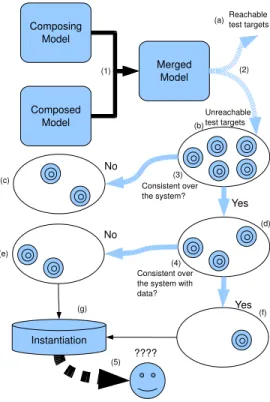
Our goal is to correct models obtained by model merging, (1) on figure 4. This latter illustrates our method correction and it is used as reference for the section 4.1.
We focus on dead code created by the model merging method and on the lack of data in the initial state from which the two problems, inconsistent test targets and incomplete ini-tial state, originates.
First, we present in 4.1 our methods for checking the cor-rectness of the test targets. Then, we give, in 4.2, an example of the behavior computation that we use for our detections. We further explain in 4.3 how to get the inconsistent behav-iors and, eventually, how to get a minimal instanciation of the initial state in 4.4.
4.1
Correction Methods
The model-based testing approach of TD aims at produc-ing tests that cover the tests targets, (2). These tests are composed of sequences of operations that reach a state in which a behavior (ie. a test target) can be activated (a). If TD can not find such a sequence, the behavior is declared unreachable (2).
As test targets coverage is used to give an indication of the quality of the produced test suite, the fact that the first two cases are reported as ”unreacheable” falsifies the results of the test generation, and may let the user think that this step did not fully succeed, whereas inconsistent targets introduce a disturbance in the statistics. We attempt to resolve that. The first step of the correction (3) is to find behavior which is inconsistent (ie. incoherente) over any possible configu-ration of the system. This inconsistent behavior (c) is un-reachable behavior because the conditions representing the states of the behavior are not sastifiable. This may be due to an incoherence of the system (invariant or constantes) and we invite the user to correct is model by classic static verifi-cation like XX. If no error exist in the system, this behavior is extracted from a dead code because of a bad modelisation of the behavior. In the model merging process, operation calls are substitued by copies of the entire operation,
in-Figure 4: Correction method
stead of using only the relevant part (a specific execution path of the called operation), creating inconsistent behav-ior (dead code), that may only be determined by evaluating the behavior conditions. As the model merging process may produce this kind of behaviors, behaviors extracted from a dead code, we invite the user to verify their origins to filtrate them on test generation process if necessary and otherwise to correct them in the model.
The second step of the correction (4) take the rest of un-reachable behavior (d) and find the behaviors which is in-consistent over the system limited by a data pool. In our case the limitation is calculate with the instance diagram. In classic Model Based Testing context this limitation is done on the model before test generation, due to its complexity, by enumerate the abstract data [XX]. These kind of incon-sistent behaviors (e) is due to a problem on data. Some data is missing or must not be exists because of a problem in the data pool. We give an instantiation (g) of the sys-tem providing to the user a help to verify if the data pool is correct (5). The rest of behaviors (f), which are consistent over the system with the limitation data, may be due to a problem in preamble computation of test generation, its need some object instances creation but is limited in search depth computation (a bounded time), or due to an activable behavior which is really unreachable. We give as before an instantiation (g) that may help the user to help the preamble computation or to conclude on the reachability of the behav-ior (5) and we invite him to use reachiability test method [XX]3
too.
We present, in the next sections, the techniques use for 3
comme les travaux de ROMEO OH MON ROMEO...
the correction more precisely.
4.2
Behavior Example
In order to illustrate our method of merging correction on the validate operation in an understable manner, we trans-late and more simplify this operation into an imperative orientedobject programmation language (similar to Java -pseudo-Java) with quantifiers, whose semantics is equivalent to the TD interpretation of OCL. The code below gives the translation in pseudo-Java of the validate operation.
i f ( c u r r e n t U s e r . l o g i n = v a l i d a t e M s g . l o g i n and c u r r e n t U s e r . s e s s i o n . s e s s i o n I d = v a l i d a t e M s g . s e s s i o n I d ) { p s l o g i n m s g . u s e r 2 = s t r . o n l i n e S t o r e and p s l o g i n m s g . p a s s w o r d 2 = s t r . s t o r e P a s s w o r d and /∗ C o d e f r o m l o g i n i s b r o u g h t h e r e ∗ / i f ( e x i s t s ( c | c : p s . c u s t o m e r and c . l o g i n = p s l o g i n m s g . u s e r 2 and c . p a s s w o r d = p s l o g i n m s g . p a s s w o r d 2 ) ) { /∗ b u s i n e s s c o d e , u s e l e s s f o r t h e e x a m p l e ∗ / } e l s e { p s . p s l o g i n r e s p o n s e . r e s C o d e 2 = −1 } and /∗ e n d o f l o g i n c o d e ∗ / p s l o g i n r e s p o n s e 2 = p s . p s l o g i n r e s p o n s e and i f ( p s l o g i n r e s p o n s e 2 . r e s C o d e = 0 ) { /∗ b u s i n e s s c o d e , u s e l e s s f o r t h e e x a m p l e ∗ / o s v a l i d a t e r e s p o n s e 2 . r e s C o d e = 0 } e l s e { o s v a l i d a t e r e s p o n s e 2 . r e s C o d e = −1 } } e l s e { o s v a l i d a t e r e s p o n s e 2 . r e s C o d e = −1 } and r e s u l t = o s v a l i d a t e r e s p o n s e 2
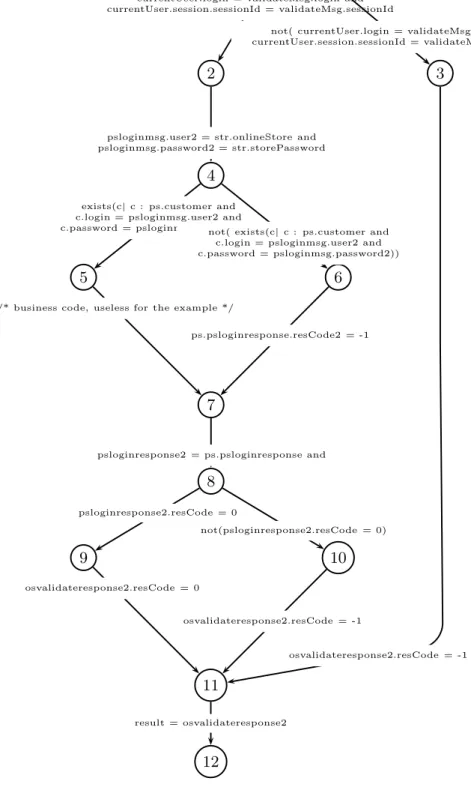
We can extract the control flow graph of this translated example as done in [?]. This graph is depicted in Fig. 5.
Behaviors are then computed by a depth-first search in the resulting graph. In this paper we interest of the third behavior, the path (1, 2, 4, 6, 7, 8, 9, 11, 12), and the fourth behavior, the path (1, 2, 4, 6, 7, 8, 10, 11, 12), of 5.
Behavior
b3of the login validation (i).
The expression of the behavior b3is given by the following set-theoretical predicate: currentUser.login = validateMsg.login ∧ currentUser.session.sessionId = validateMsg.sessionId ∧ psloginmsg.user2 = str.onlineStore ∧ psloginmsg.password2 = str.storePassword ∧ ¬ ( ∃ c . c ∈ ps.customer ∧ c.login = psloginmsg.user2 ∧ c.password = psloginmsg.password2)) ∧ ps.psloginresponse.resCode2 = -1 ∧ psloginresponse2 = ps.psloginresponse ∧ psloginresponse2.resCode = 0 ∧ osvalidateresponse2.resCode = 0 ∧ result = osvalidateresponse2
The fourth, b4, is the same behavior as b3 except for last part, psloginresponse2.resCode = 0 ∧ osvalidateresponse2.resCode = 0 ∧ result = osvalidateresponse2 which became ¬(psloginresponse2.resCode = 0) ∧ osvalidateresponse2.resCode = -1 ∧ result = osvalidateresponse2
1
2
3
4
5
6
7
8
9
10
11
12
currentUser.login = validateMsg.login and currentUser.session.sessionId = validateMsg.sessionId
not( currentUser.login = validateMsg.login and currentUser.session.sessionId = validateMsg.sessionId)
psloginmsg.user2 = str.onlineStore and psloginmsg.password2 = str.storePassword
exists(c| c : ps.customer and c.login = psloginmsg.user2 and
c.password = psloginmsg.password2)not( exists(c| c : ps.customer and c.login = psloginmsg.user2 and c.password = psloginmsg.password2))
/* business code, useless for the example */
ps.psloginresponse.resCode2 = -1
psloginresponse2 = ps.psloginresponse and
psloginresponse2.resCode = 0 not(psloginresponse2.resCode = 0) osvalidateresponse2.resCode = 0 osvalidateresponse2.resCode = -1 osvalidateresponse2.resCode = -1 result = osvalidateresponse2
4.3
Consistency of Test Targets
Behavior b3illustrates the problem of inconsistency of de-clared “unreachable” behaviors. This latter describes a login validation, that requires the user not to be logged
p s . p s l o g i n r e s p o n s e . r e s C o d e 2 = −1
after a successful authentication.
o s v a l i d a t e r e s p o n s e 2 . r e s C o d e = 0
This is clearly an incoherent behavior that is introduced by the model merging process.
The consistency checking ensures that the behavior is co-herent by verifying that a proof obligation, called the be-havior consistency formula (BCF), is satisfiable. A BCF is the conjunction of the predicates of a behavior, it represents the minimal condition to activate the behavior, in terms of system states that in which the behavior may be activated. To be able to verify this formula using automated tools, it is necessary to dispose of a representation of the system state in the theory used by the prover/solver that will be employed. We have chosen to employ a set-theoretic repre-sentation of the system state. As in a previous work [?], the object oriented systems we consider are represented using sets, total functions and relations, according to the following principles. The system heap is represented by an abstract set of atoms that give the addresses of the possible objects. Existing class instances are pairwise distinct subsets of this latter. Each instance attribute is a total function mapping the instance to its value in a given domain. Each binary UML association is represented by a relation from the first to the second class instances. Thus, for a given instance, it is possible (using domain or image restriction of the relation) to know to which instances it is linked. The data model is extracted from the considered UML class diagrams. The set of existing instances is given by the instance diagram considered by TD.
BCF of the login validation.
A part of the BCF expression of behavior b3 is given by the following set-theoretical predicate:
SETS INSTANCES PARCELSERVICE; INSTANCES ONLINESTORE ; INSTANCES CUSTOMER2; INSTANCES SESSION2 ; . . . VARIABLES p a r c e l S e r v i c e , o n l i n e S t o r e , c u s t o m e r 2 , c u s t o m e r 2 2 l o g i n , c u s t o m e r 2 2 p a s s w o r d , s e s s i o n 2 , s e s s i o n 2 2 i d , i s L o g g e d I n 2 , knows2 , manages2 , i s L o g g e d W i t h 2 , . . . INVARIANT
o n l i n e S t o r e <: INSTANCES ONLINESTORE & p a r c e l S e r v i c e <: INSTANCES PARCELSERVICE & c u s t o m e r 2 <: INSTANCES CUSTOMER2 & c u s t o m e r 2 2 l o g i n : c u s t o m e r 2 −−> STR & c u s t o m e r 2 2 p a s s w o r d : c u s t o m e r 2 −−> STR & s e s s i o n 2 <: INSTANCES SESSION2 & s e s s i o n 2 2 i d : s e s s i o n 2 −−> STR & i s L o g g e d I n 2 : c u s t o m e r 2 <−−> p a r c e l S e r v i c e & knows2 : c u s t o m e r 2 −−> p a r c e l S e r v i c e & i s L o g g e d W i t h 2 : c u s t o m e r 2 <−> s e s s i o n 2 & m anages 2 : s e s s i o n 2 −−> p a r c e l S e r v i c e & . . . . & ( i ) // P r e d i c a t e o f B3
The BCF is verified using satisfiability checker tools, namely SMT-provers and a set-theoretical solver. Provers use de-ductive techniques that make it possible to deal with infi-nite data, such as abstract sets whose content and size is not specified. Constraint solver manage the constraints us-ing consistency algorithms. Unfortunately, consistency al-gorithms are not complete, and thus, an enumeration of the solutions, named labeling, is potentially necessary for ensur-ing the satisfiability of the constraints.
In our experimentation, we use the CLPS-BZ solver [7] (that natively supports set theory) and the SMT provers [22], in which the set theoretical structures are expressed using the array theory (suitable for representing sets and func-tions) as done in [10] and [11].
For the BCF of behavior b3, the tools automatically con-clude on the unsatisfiability of the formula. The CLPS-BZ solver give a result in XX.XXs and the SMT provers Yices answers in YY.YYs, Z3 in ZZ.ZZs and haRVey in TT.TTs.
[[FD: un petit tableau complet des 13 insatisfiables avec les temps de calcul, ca serait vraiment nickel ...]]
Behavior b4consistency formula is also declare unsatifiable in similar times.
With this method, we can automatically find automat-ically inconsistent behavior of the operations of an UM-L/OCL model.
For the example model, 39 generate tests were generated, excluding 13 “unreachable” targets. Among these, we found 8 inconsistent behaviors meaning that the remaining 5 be-haviors are “real” unreachable ones.
When checking the BCF we check if the behavior is consis-tent for a given set of existing instances at the initial state. This point is crucial since objects can not be created dy-namically when executing the UML models (requirement of TD).
We now propose to check if the inconsistency of the be-haviors may possibly due to an incorrect initial state.
4.4
Computation of a Relevant Initial State
As seen before, the inconsistency of behaviors may be due to an erroneous initial state of the UML
After filtrate the inconsistent behaviors, we propose a in-stantiation of the system parameters for a behavior. We need enough elements in our database of object, the instance diagram, to represent a state, a collection of objects. If we haven’t this, we can not represent the state, and so, we can not reach it. Our method get an instanciation of parametres providing the representation of a least one state activating a behavior.
The behavior b4illustrate the instantiation problem. This behavior describes a login validation failure, that requires the user doesn’t exist
not ( e x i s t s ( c | c : p s . c u s t o m e r and
c . l o g i n = p s l o g i n m s g . u s e r 2 and c . p a s s w o r d = p s l o g i n m s g . p a s s w o r d 2 ) )
but in the instance diagram this user exist. In fact for a specific instantiation we can be log or not but not both.
It clearly an unreacheable behavior due to a lack data or a bad data. We want to compute an instantiation needed to activate the behavior in the way to compare each other.
The instantiation approach represent the data structure of the system with the set theory, a set for each parameter, and use the BCF to put enough elements in them and activate the asociated behavior.
We can only instanciate consistent behavior because com-pute the instantiation of an inconsistent behavior is useless as it is not activable with any instantiation.
4.4.1
Data Structure Representation
As in the section 4.3 we get the BCF with the system representation in predicative form over set theory. Each parameter becomes a set pairwise distinct and is considering as primary sort.
We compute the graph of sort dependency [5], a repre-sentation of dependency between sorts. The nodes are the sorts and the edges are the dependencies. A sort s depends of others sorts s1, . . . , sn if there exists a functional symbol whose signature is s1, . . . , sn→ s. Intuitively it is the case when an element transformer adds some elements of some sorts in an other sort.
At this point, we obtain the data structure of the model over the set theory and their dependencies.
4.4.2
Instantiation Computation
The instantiation computation gives a over-approximation of needed objects in parameters for the behaviors and reduce it.
We want to get each variables of the BCF representing a system object and put in in the appropriated sort.
We skomelize the BCF to extract these variables, that become constants of the herbrand universe, and we use in-formations of the behavior predicate to fill the data structure with these constants.
A simple way to do this is to duplicate and add each con-stants in each sort. By this way we are sure that any variable can be instantiate by any sort.
In the same time, we use the graph of sort dependency to complete the instantiation. For each dependency and each combination of constant which can be use to apply the function, we add a new fresh constants corresponding to the result of the function application over this combination.
The problem of this approach is the Herbrand universe calculus can not terminate. This is due to a cycle in the de-pendency graph of sort. Indeed the computation of universe Herbrand is finite if and only if the graph is acyclic.
We check the BCF on a solver with this upper approxi-mation as parameter domain to reduce it and obtain a min-imalist behavior instantiation.
We obtain for the behavior b4 and the U SER class an intantiation without an user c where the condition
c.login = psloginmsg.user2 and c.password = psloginmsg.password2 is verified.
4.4.3
Model Instantiation
The model instantiation consists in computing an unique instantiation for all behaviors in the same time, and so the entire model.
We extend the BCF to the Most General Behavior Con-sistency Formula MGBCF for the over-approximation com-putation and the reduction.
The Most General Behavior Consistency Formula is the conjunction
P ∧
V
(∃X
i.BCF
i(X
i))
where for each behavior bi, Xiis a distinct tuple of state variable and BCFi is the BCF of bi over Xi and P is the
common part of each BCF, such as parameters, constants and their properties.
We get the model instantiation with the same method of behavior instantiation but we use no more the BCF but the MBCF.
In our example we can not compute the model instanti-ation because the MBCF is not consistent. It due to the the condition c.login = psloginmsg.user2 and c.password = psloginmsg.password2 of the user c can not be true and false in the same time.
With this method, we can find automatically a behavior instanciation of a UML/OCL model.
For the example model, which still have 5 unreachable behaviors with unkown reason. We find an instanciation of each of them.
5.
CONCLUSION AND FUTURE WORK
In this article, we introduced a method used to merge UML models for test generation. The method takes place in a quality evaluation framework for WS: iTac-QoS. In this framework, WS vendors produce a UML model of their prod-uct. Tests are generated from this model, and result of their execution are translated into marks, allowing customers to evaluate quality of the WS.
Our framework was not able to test WS which acted as client of other WS. This was due to the fact that a WS vendor is not able to produce a valid UML model of a foreign product. We solved this problem with our model merging method.
This method is done in four steps. The first one is to transform state-charts into OCL code. Once done, a new class diagram is created, which includes class from the sev-eral models. To avoid any overwriting due to two classes sharing the same name, classes are renamed before the cre-ation of the new class diagram. The third step is to merge all OCL code into a single class (the one modeling the WS under test). We have to do this because the test tool we use (TD), does not handle operation call. The solution proposed to solve this problem is based on a another specificity of the test tool. OCL code is interpreted as a sequential language, not a parallel one. The last step of model merging is to cre-ate a new instance diagram.
To the best of our knowledge, this work is an innovation in model merging. We do not know any solution allowing to automatically merge UML models for test generation. This solution is has three main advantages. The first one is its portability. Except for OCL merging, it can be applied to classical UML model which are not designed for TD. The OCL merging solution only works because of an TD speci-ficity, but has been designed to solve a lack of this software. The other advantages are more specifics to our framework. The first one is that our framework can now evaluate quality of WS performing distributed compositions. The last one is that it simplifies work for WS vendor: they just have to model their own product, and our framework automatically produce a model describing the whole composition. They do not have to specify composition pattern for merging. Com-position specification is done by describing composed WS interface in the class diagram, and to call operations in OCL code.
In order to simplify description of interfaces in class diagram, we created a tool translating WSDL files in XMI (http://lifc.
univ-fcomte.fr/˜pretre/itac-qos/wsdl2xmi.php.html). With this tool, describing interfaces is really simple and automated.
We are currently working on a last improvement for our method: initial state completion. As shown in section 3.5, TD was not able to generate some tests on model produced by our example.
Our goal is to be able to automatically classify those test goals: do they concern inconsistent behaviour or can we add data to make this test goal activable? Once inconsistent test goals set aside, we will have to complete models to reach all test goals.
6.
REFERENCES
[1] B. Benatallah, M. Dumas, M.-C. Fauvet, and F. A. Rabhi. Towards patterns of web services composition. pages 265–296, 2003.
[2] A. Bertolino and A. Polini. The audition framework for testing web services interoperability. In
EUROMICRO-SEAA, pages 134–142. IEEE Computer Society, 2005.
[3] J. B´ezivin. From object composition to model transformation with the mda. In TOOLS ’01: Proceedings of the 39th International Conference and Exhibition on Technology of Object-Oriented
Languages and Systems (TOOLS39), page 350, Washington, DC, USA, 2001. IEEE Computer Society. [4] A. Boronat, J. A. Cars´ı, I. Ramos, and P. Letelier.
Formal model merging applied to class diagram integration. Electron. Notes Theor. Comput. Sci., 166:5–26, 2007.
[5] F. Bouquet, J.-F. Couchot, F. Dadeau, and A. Giorgetti. Instantiation of parameterized data structures for model-based testing. In B’2007, the 7th Int. B Conference, volume 4355 of LNCS, pages 96–110, Besancon, France, Jan. 2007. Springer. [6] F. Bouquet, C. Grandpierre, B. Legeard, F. Peureux,
N. Vacelet, and M. Utting. A subset of precise UML for model-based testing. In A-MOST’07, 3rd int. Workshop on Advances in Model Based Testing, pages 95–104, London, UK, July 2007. ACM Press.
A-MOST’O7 is colocated with ISSTA 2007, Int. Symposium on Software Testing and Analysis. [7] F. Bouquet, B. Legeard, and F. Peureux. CLPS-B: A
constraint solver to animate a B specification. International Journal on Software Tools for
Technology Transfer, STTT, 6(2):143–157, Aug. 2004. [8] E. Christensen, F. Curbera, G. Meredith, and
S. Weerawarana. Wsdl 1.1.
http://www.w3.org/TR/wsdl, 2001.
[9] S. Clarke. Extending standard uml with model composition semantics. Sci. Comput. Program., 44(1):71–100, 2002.
[10] J.-F. Couchot and F. Dadeau. Guiding the Correction of Parameterized Specifications. In Integrated Formal Methods, IFM’07, volume 4591, pages 176–194, 2007. [11] J.-F. Couchot, D. D´eharbe, A. Giorgetti, and
S. Ranise. Scalable Automated Proving and Debugging of Set-Based Specifications. JBCS, 9(2):17–36, 2003. [12] J. Estublier and A. D. Ionita. Extending uml for
model composition. In ASWEC ’05: Proceedings of the 2005 Australian conference on Software Engineering,
pages 31–38, Washington, DC, USA, 2005. IEEE Computer Society.
[13] H. Foster, S. Uchitel, J. Magee, and J. Kramer. Model-based verification of web service compositions. ase, 0:152, 2003.
[14] L. Frantzen, J. Tretmans, and R. de Vries. Towards model-based testing of web services. In A. Bertolino and A. Polini, editors, in Proceedings of International Workshop on Web Services Modeling and Testing (WS-MaTe2006), pages 67–82, Palermo, Sicily, ITALY, June 9th 2006.
[15] M. Gudgin, M. Hadley, N. Mendelsohn, J.-J. Moreau, H. F. Nielsen, A. Karmarkar, and Y. Lafon. Soap version 1.2. http://www.w3.org/TR/soap12-part1/, 2007.
[16] R. Heckel and M. Lohmann. Towards contract-based testing of web services. In M. Pezz´e, editor,
Proceedings of the International Workshop on Test and Analysis of Component Based Systems (TACoS 2004), volume 116, pages 145–156, 2005.
[17] R. Heckel and L. Mariani. Automatic conformance testing of web services. In In proceedings of the 8th International Conference on Fundamental Approaches to Software Engineering (FASE 2005), pages 34–48. Springer-Verlag, 2005.
[18] E. Marcos, V. de Castro, and B. Vela. Representing web services with uml: A case study. In ICSOC, pages 17–27, 2003.
[19] OASIS UDDI specification TC. Uddi version 3.0.2. http://uddi.org/pubs/uddi v3.htm, 2005.
[20] V. Pretre, F. Bouquet, and C. Lang. A model-based validation framework for web services. In STV07, Procs of the 5th workshop on Systems Testing and Validation, pages 63–76, Paris, France, Dec. 2007. [21] V. Pretre, F. Bouquet, and C. Lang. Automating uml
models merging: application of the method. Research Report RR2008-09, LIFC, october 2008.
[22] S. Ranise and C. Tinelli. The Satisfiability Modulo Theories Library (SMT-LIB). www.SMT-LIB.org, 2006.
[23] A. Staikopoulos and B. Bordbar. A comparative study of metamodel integration and interoperability in uml and web services. In ECMDA-FA, pages 145–159, 2005.
[24] S. Th¨one, R. Depke, and G. Engels. Process-oriented, flexible composition of web services with uml. In ER (Workshops), pages 390–401, 2002.
[25] W. Vogels. Web services are not distributed objects. IEEE Internet Computing, 7(6):59–66, 2003.