HAL Id: hal-02017244
https://hal-ifp.archives-ouvertes.fr/hal-02017244
Submitted on 13 Feb 2019
HAL is a multi-disciplinary open access archive for the deposit and dissemination of sci-entific research documents, whether they are pub-lished or not. The documents may come from teaching and research institutions in France or abroad, or from public or private research centers.
L’archive ouverte pluridisciplinaire HAL, est destinée au dépôt et à la diffusion de documents scientifiques de niveau recherche, publiés ou non, émanant des établissements d’enseignement et de recherche français ou étrangers, des laboratoires publics ou privés.
Catalytic Hydrotreatment: Two Cations Disulfide Layers
in the MoxW(1-x)S2 Lamellar Solid Solution
C. Thomazeau, C. Geantet, M. Lacroix, M. Danot, V. Harle
To cite this version:
C. Thomazeau, C. Geantet, M. Lacroix, M. Danot, V. Harle. EXAFS Characterization of New Active Phases for Catalytic Hydrotreatment: Two Cations Disulfide Layers in the MoxW(1-x)S2 Lamellar Solid Solution. Oil & Gas Science and Technology - Revue d’IFP Energies nouvelles, Institut Français du Pétrole, 2005, 60 (5), pp.781-790. �10.2516/ogst:2005055�. �hal-02017244�
Oil & Gas Science and Technology – Rev. IFP, Vol. 60 (2005), No. 5, pp. 781-790
Copyright © 2005, Institut français du pétrole
EXAFS Characterization of New Active Phases
for Catalytic Hydrotreatment:
Two Cations Disulfide Layers
in the Mo
x
W
(1-x)
S
2
Lamellar Solid Solution
C. Thomazeau
1, C. Geantet
2*, M. Lacroix
2, M. Danot
3and V. Harle
1 1 IFP-Lyon, BP 3, 69390 Vernaison - France2 IRC-CNRS, 2 avenue Albert Einstein, 69626 Villeurbanne - France
3 IMJR, UMR 6502, CNRS-Univ. Nantes, 2 rue de la Houssinière, 44322 Nantes - France email: cecile.thomazeau@ifp.fr christophe.geantet@catalyse.univlyon1.fr lacroix@catalyse.cnrs.fr
-michel.danot@cnrs-imn.fr, virginie.harle@eu.rhodia.com
* corresponding author
Résumé — Caractérisation par EXAFS de nouvelles phases actives pour l’hydrotraitement catalytique : les couches disulfures à deux cations de la solution solide lamellaire MoxW(1-x)S2— Des composés Mo0.5W0.5S2 ont été préparés à l’état massique et à l'état dispersé sur alumine. L’absorption X, seule technique permettant d'obtenir cette information, montre que les deux cations Mo et W sont présents au sein de chaque couche [MS2], selon un modèle de solution solide intrafeuillet. L’intérêt de ce système mixte est de pouvoir moduler la force de liaison Métal-Soufre considérée comme le paramètre clé de l’activité catalytique des sulfures de métaux de transition. Cette solution solide est toujours présente après promotion par le Ni des systèmes massiques ou supportés sur alumine.
Abstract — EXAFS Characterization of New Active Phases for Catalytic Hydrotreatment: Two
Cations Disulfide Layers in the MoxW(1-x)S2 Lamellar Solid Solution — Bulk and alumina-supported
Mo0.5W0.5S2compounds were prepared. The presence of both molybdenum and tungsten in every [MS2] layer (intralayer solid solution) was evidenced using EXAFS spectroscopy, the only local method which can provide such relevant structural information. The catalytic interest of such solid solution is to provide a continuous variation of M-S bond strength which is considered as the key parameter of the catalytic activity transition metal sulfides. The solid solution is maintained after promotion by Ni either on unsupported or supported state.
Synchrotron and Neutron Solutions to Oil Industry Problems
Utilisation des grands instruments analytiques dans l’industrie pétrolière
INTRODUCTION
Environmental legislation [1] concerning emissions of SOx and NOx gas becomes more and more drastic. In most advanced countries, the diesel sulfur allowable limit will be as low as 50 wppm this year and probably 10 wppm before 2010. In order to abide by these stringent rules, tremendous research efforts are made in both fields of formulation of new hydrotreating catalysts and design of new processes.
Catalytic activities of various transition metal sulfides have been shown to be related to the M-S bond strength according to volcano curve trends [2-4]. Use of such a M-S bond descriptor thus opens new perspectives for the design of catalytic active phases [4]. Effectively, it appears that catalytic activity could be improved by pertinent adjustment of the M-S bond energy. Such an adjustment could be achieved through synthesis of solid solutions involving two transition metal sulfides with different cations.
1 EXAFS SPECTROSCOPY, A POWERFUL TOOL FOR THE CHARACTERIZATION OF LAMELLAR DISULFIDES SYSTEMS
In the field of hydrotreating catalysts, active phases are based on the use of lamellar disulfides such as MoS2or WS2 dispersed on alumina and promoted by Co or Ni. In such MS2lamellar transition metal disulfides, the structural unit is a layer constituted by three hexagonal atomic planes, a cationic one “sandwiched” by two anionic ones [5]. Within the layer, every M atom is surrounded by a sulfur trigonal prism consisting of six crystallographically equivalent sulfur atoms. The crystals result from stacking of such layers along the c-axis according to the scheme [S-M-S]∞. Such struc-tures are highly anisotropic because strong iono-covalent metal-sulfur bonds within the S-M-S layer coexist with weak interactions between adjacent layers (this weakness explains the inter-layer space to be known as the van der Waals gap).
As discussed above, it can be interesting to try to associate W and Mo in a lamellar disulfide solid solution MoxW(1-x)S2,
as it was already done with Nb and Mo (NbxMo(1-x)S2solid solution [6]). A priori, two structural models can be envisioned for such solid solutions involving two cations, Ma
and Mb:
– every layer can contain only one type of cation and the mixed system results from stacking of homocationic [MaS
2] and [M bS
2] layers (interlayers solid solution);
– or the two cations can be present in every layer and the mixed system arises from stacking of heterocationic [Ma
xM b
(1-x)S2] layers (intralayer solid solution).
A third possibility is that the synthesis attempt was unsuccessful and led to a two phase system (MaS
2+ M bS
2). If
well-crystallized compounds are concerned, X-ray diffraction technique could be expected to be an efficient tool for structural study.
For a Ma xM
b
(1-x)S2solid solution, however, the position of
the diffraction lines cannot allow to choose between the interlayers and intralayer models, due to the statistical character of the X ray-diffraction technique. Effectively, in both cases, the refined cell parameters will be found to be intermediate between those of MaS
2and M bS
2and to depend
upon x, according to the Vegard’s law which should be obeyed, at least approximately. In the cases of ordered arrangements of the Maand Mbcations within the a-a plane
of a layer (intralayer solid solution) or of the [MaS 2] and
[MbS
2] layers along the c-axis (interlayers solid solution),
superstructure reflexions concerning respectively a or c would provide valuable information. However, to our know-ledge, XRD study of such systems never evidenced any superstructure line, even for particular Ma/Mbatomic ratios.
Furthermore in the case of supported catalysts, no XRD lines are detected due to the nanosize of the lamellar crystallites.
Identification of a two phase system (MaS 2+ M
bS 2) from
XRD results appears on the contrary very easy since the diffraction pattern will contain both sets of the two disulfide component diffraction lines. It is effectively what is observed when NbS2and MoS2 coexist [6]. However, for WS2 and MoS2, no conclusion can be drawn because the diffraction lines of these two disulfides are so close (Table 1) that it is impossible to decide whether the pattern contains a unique
TABLE 1
Crystallographic parameters of the 2H varieties (SG: P63/mmc) and atomic distances of NbS2, WS2, and MoS2(from ICSD database)
MoS2-2H WS2-2H NbS2-2H a (Å) 3.161(12) 3.154 3.31 c (Å) 12.298(5) 12.362 11.89 Cation atomic position (1/3, 2/3, 1/4) (1/3, 2/3, 1/4) (0,0,1/4) Sulfur atomic position (1/3, 2/3, 0.621(4)) (1/3, 2/3, 0.6225) (1/3, 2/3, 0.125) Distance M-M (Å) 3.161 3.154 3.31 Distance M-S (Å) 2.41 2.41 2.42
C Thomazeau et al. / EXAFS Characterization of New Active Phases for Catalytic Hydrotreatment
line set (solid solution) or two unresolved line sets (two phase system).
In this case, the problem can be solved using Energy Dispersive X-ray Spectroscopy (EDX or EDXS) analysis: for a two phase system, rather large one cation domains are observed while, for a solid solution, the two cations are found to coexist even for the smallest probe sizes.
The conclusion is that a two phase system can always be identified. If XRD sometimes cannot, EDX analysis always can. On the contrary, interlayers and intralayer solid solutions cannot be distinguished from each other, neither from XRD nor from EDX analysis, and only a local method such as EXAFS can provide relevant information.
For a disulfide system, the EXAFS spectrum at the cation edges consists of two contributions respectively related to the anion and cation in-layer neighbours of the absorbing atom. The neighbours in adjacent layers are located at high distances from the absorbing atom and, except for highly-organized phases (which are not of paramount interest in catalysis), do not significantly contribute to the EXAFS signal, as shown by the Fourier transform (FT) of the EXAFS spectrum, which contain only the two in-layer peaks. It is the second peak (in-layer cation neighbours) which can be expected to allow the solid solution type to be identified. For an interlayer solid solution, the Maabsorbing cation will
“see” only Maneighbours and the Mb absorbing cation only
Mb neighbours, just as in the case of a two phase system
(homocationic layers in both cases). On the contrary, for an intralayer solid solution, both Maand Mbabsorbing cations
will “see” Maand Mb neighbours since these two cations are
present in every layer. It follows that EXAFS is not the relevant tool to choose between the hypothesis of a two phase system and that of an interlayers solid solution (it is not very important since the information can be obtained from EDX analysis) but perfectly allows interlayer and intralayer solid solutions to be distinguished.
This can be illustrated by the NbxMo(1-x)S2and MoxW(1-x)S2 series, and it will be seen that, depending upon the two cations involved, the information obtained is different but in both cases allows the nature of the material to be clearly established.
Alumina-supported Nb- and Mo-containing sulfide parti-cles were studied using the EXAFS technique. At the Nb K-edge for instance, the in-layer cation neighbours (second peak of the FT’s) should be only Nb atoms in the case of a NbS2+ MoS2two phase system and in that of an interlayer solid solution (homocationic layers). For an intralayer solid solution, Nb and Mo atoms should be present in the cation surrounding of Nb. The problem is that Nb and Mo backscatterers cannot be distinguished: due to their adjacent positions in the same line of the Mendeleev’s table (close atomic numbers), their backscattering phases and amplitudes are nearly identical so that Nb- and Mo-neighbour contributions to EXAFS spectra are also nearly identical.
Consequently, the fact that simple eye observation of the FT’s does not reveal any significant difference between spectra corresponding to different compositions does not provide any information. However, refinement of the EXAFS data shows that the distance from the absorbing niobium to its in-layer cation neighbours varies with the composition. More precisely, starting from 3.33 Å (the Nb-Nb distance in NbS2) for x = 1, it decreases with increasing Mo content. In MoS2, the Mo-Mo distance is only 3.16 Å. It thus appears that, as the Mo content increases, the observed decrease of the distance between the Nb absorbing cation and its in-layer cation neighbours reflects progressive replacement of Nb neighbours by Mo neighbours, which can only be explained by the intralayer solid solution model. Treatment of the EXAFS spectra recorded at the Mo K-edge shows that, starting from 3.16 Å (the Mo-Mo distance in MoS2) for x = 0, the distance between the Mo absorbing cation and its in-layer cation neighbours increases with the Nb content, which again evidences the intralayer solid solution.
Different massic disulfide systems containing W and Mo cations were prepared, from 1273 K heating of W + Mo + S mixtures, and from thermal decomposition at 673 K, under H2/H2S (15%) atmosphere, of a thiosel precursor obtained through co-crystallization of ammonium thiomolybdate and thiotungstate [7]. For all these compounds, the EXAFS distance between the absorbing cation and its cation neighbours cannot be expected to vary significantly since the W-W distance in WS2 and the Mo-Mo distance in MoS2 differ by less than 0.01 Å, which is obviously smaller than the EXAFS distance refinement accuracy. However, in this case, the two backscatterers, W and Mo, can easily be distinguished. Due to their largely different atomic numbers, the variations of their backscattering phases and amplitudes in the k-space are very different. For this reason, in the EXAFS spectra, a W neighbour contribution and a Mo neighbour contribution are largely different too. Actually, simple observation of the FT’s shows appreciable variation of the second peak with the composition. It is a first indication of the presence of the two cations in every layer. Data refinements effectively show that reproduction of the second peak (at both W LIII- and Mo K-edge) requires presence of W and Mo backscatterers in relative amounts consistent with the nominal composition. It can thus be deduced that, in this case too, the structural model corresponds to the intralayer solid solution.
2 THE PRESENT STUDY
The present study was undertaken in order to obtain new alumina-supported catalysts containing nickel-doped MoxW(1-x)S2 solid solution as the active phase. For this purpose, we first checked that the solid solution can be 783
retained in unsupported nickel-doped MoxW(1-x)S2 samples. Then, we prepared alumina supported MoxW(1-x)S2 and, in the last step of this study, introduced the nickel dopant for the desired supported materials to be obtained. In all cases, EXAFS measurements were performed in order to evidence the presence of the mixed cations [MoxW(1-x)S2] layers characteristic of the intralayer solid solution.
3 EXPERIMENTAL
3.1 Catalysts Preparation 3.1.1 Unsupported Samples
MoxW(1-x)S2 compounds were prepared using ammonium tetrathiomolybdate (NH4)2MoS4 and ammonium tetra-thiotungstate (NH4)2WS4salt precursors. Ammonium tetra-thiomolybdate and ammonium tetrathiotungstate were prepared and characterized according to the procedures previously described [8-10]. Synthesized (NH4)2WS4 and (NH4)2MoS4, taken in various proportions, were then dissolved in water. The solvent was progressively removed under vacuum (T = 333 K). The solids resulting from this co-crystallization were then heated for two hours at 673 K under a H2/H2S (15%) flow (6 L/h) in order to obtain the MoS2, Mo0.5W0.5S2, and WS2compounds.
The nickel promoter was then introduced with an atomic ratio Ni/(Ni + Mo + W) = 0.3. The nitrate precursor salt Ni(NO3)2,6H2O was first dissolved in acetone. Then, the solution was impregnated on MoS2, WS2, and Mo0.5W0.5S2 compounds. After 8 hours of maturation, the solid was then dried at 313 K overnight and treated for two hours at 673 K under H2/H2S (15%), flow (6 L/h). These Ni-promoted MoS2, WS2, and Mo0.5W0.5S2 unsupported sulfides are respectively called NiMo, NiW, and NiMoW.
3.1.2 Supported Catalysts
γ-Al2O3(specific surface area: 250 m2.g–1, porous volume:
0.51 cm3.g–1) was first crushed and sieved in the 80-125 µm
range. The catalysts were prepared by incipient wetness coimpregnation of the support with solutions of ammonium heptamolybdate (NH4)6Mo7O24,4H2O and ammonium metatungstate (NH4)6H2W12O40,4H2O. Before impregnation, the pH of the solutions was adjusted to 9.5 with diluted ammonia for monomeric species (WO42–or MoO
4
2–) to be
predominant [11]. Effectively, introduction of Mo and W as anionic monomers might be a favourable factor for the obtention of an intralayer solid solution since it limits the risk of monocationic seeds formation. The total molar amount of metal impregnated on the alumina (Mo, W or Mo + W) was kept constant (see Table 2).
The promoted catalysts were prepared through co-impregnation of the alumina support by solutions of (NH4)6W12O39,xH2O, (NH4)6Mo7O24,4H2O, and Ni(NO3)2, 6H2O, at a pH adjusted to 9.5. Nickel nitrate was introduced in the expected optimal ratio Ni/(Ni + Mo + W) = 0.3.
After coimpregnation and maturation, unpromoted and promoted catalysts were oven-dried at overnight at 393 K and calcined in air at 773 K during 2 hours. The catalysts were then sulfided in a flow reactor (6 L/h), at 723 K during 2 hours, under H2/H2S (10%).
3.2 Catalysts Characterization
XRD patterns of samples were recorded using a Bruker D5005 diffractometer (Cu Kα1 radiation).
High resolution electron microscopy was performed using a JEOL 2010 TEM microscope (point to point resolution 0.19 nm) equipped with a EDXS Link-Isis detector. Such detector analyses the energy of the X-ray generated by inner-shell ionizations of the atoms in the material by a convergent incident electron probe (smallest probe available 1 nm). For sample preparation, the catalysts were ultrasonically dispersed in ethanol and the suspension was then collected on a carbon-coated copper grid.
EXAFS spectra were recorded at the Laboratoire
d’Utilisation du Rayonnement Electromagnétique (LURE),
the French Synchrotron Laboratory, on the XAS 13
TABLE 2
Characteristics of alumina-supported MoS2, W0.50Mo0.50S2, WS2and corresponding Ni-doped samples: atom and weight % loadings, average length and stacking obtained from TEM
n (Mo) n (W) n (Ni) % Mo % W % Ni N l (nm) MoS2/Al2O3 1.04 – – 8.6 – – 1.6 2.2 Mo0.50W0.50S2/Al2O3 0.52 0.52 – 4.3 7.7 – 2.0 2.0 WS2/Al2O3 – 1.04 – – 15.4 – 1.5 2.5 Ni-MoS2/Al2O3 1.04 – 0.45 8.3 – 2.0 1.7 2.5 Ni-Mo0.50W0.50S2/Al2O3 0.52 0.52 0.45 4.3 7.7 2.1 1.6 2.3 Ni-WS2/Al2O3 – 1.04 0.45 – 15.4 2.0 1.6 3.0
* n(Mo), n(W), n(Ni): mmol/g Al2O3; %Mo, %W, %Ni: weight percent. ** N, l (nm): stacking and length of the sulfide obtained from MET.
C Thomazeau et al. / EXAFS Characterization of New Active Phases for Catalytic Hydrotreatment
spectrometer, using a Si (111) monochromator for the tungsten LIIIedge (10100-11200 eV, 2 eV step, 2 s per point, sum of three spectra) and a Ge (400) one for the molybdenum K-edge (19800-21000 eV, 4 eV step, 2 s per point, sum of three spectra). The storage ring (DCI) used 1.85 GeV positrons with an average intensity of 250 mA. For the sample preparation, pellets were pressed using powder quantities calculated in order to achieve suitable absorption coefficient and edge jump. Data were collected at 80 K in the transmission mode by measurement of the beam intensities I0 and I, respectively before and after passing through the sample, using ionization chambers.
Standard analysis of the EXAFS spectra (normalization, background removal, Fourier transformation, and curve fitting) were carried out using the SEDEM software [12] with FEFF [13] theoretical phase and amplitude functions. The curve fitting procedure was performed in R-space. Fourier transformation of the normalized k3-weighted EXAFS signal
was performed over the 2.5-16 Å–1 k-range with Kaiser
window functions. Coordination numbers (N), interatomic distances (R), Debye-Waller parameters (σ2), and energy
shifts (∆E0), were used as variables in the fitting procedure. Scale factors S02were fixed at 0.8. FEFF6 was also used
to calculate for Mo-W and W-Mo (absorbing atom-backscatterer) pairs the backscattering amplitudes and phase shifts required for the fitting procedures [7].
4 RESULTS AND DISCUSSION
4.1 The Mo(1-x)WxS2Unsupported Disulfides
The X-ray diffraction patterns of the unsupported MoxW(1-x)S2 compounds (prepared from the co-crystallized thiosalts) correspond to the MoS2or WS2hexagonal structure. How-ever, important line broadening evidences poor crystalline organization, as expected for compounds obtained through a rather low temperature synthesis route. The diffractograms of the nickel-doped samples remain characteristic of a dispersed MS2-like structure (see Fig. 1).
For all the unsupported catalysts (undoped and doped), the average stacking determined from the linewidth of the (002) reflection (Table 3) ranges from 5 to 8 [MS2] layers per crystallite. The presence of the promoter does not affect this parameter except for the NiMo catalyst.
The Fourier transforms (FT’s) of the EXAFS spectra recorded at the Mo K-edge for the non-promoted MoS2 and Mo0.5W0.5S2and promoted Ni-MoS2and Ni-Mo0.5W0.5S2 un-supported sulfides are given Figure 2, respectively a) and b). The first peak of all the four FT’s corresponds to the expected anionic surrounding of molybdenum and is fairly reproduced with ≈6 sulfur neighbours at a distance d≈2.40 Å. The second peak reflects the cationic environment of molybdenum. For MoS2, it can be reproduced, as expected,
Figure 1
X-ray diffraction patterns of unsupported W0.50Mo0.50S2and Ni-W0.50Mo0.50S2.
Figure 2
a) Fourier transforms obtained at the Mo K-edge for MoS2 and W0.50Mo0.50S2; b) Fourier transforms obtained at the Mo K-edge for Ni-MoS2and Ni-W0.50Mo0.50S2.
considering ≈6 molybdenum neighbours (N(Mo) = 5.9,
Table 4). Its intensity noticeably decreases from MoS2 to Mo0.5W0.5S2 which suggests for the latter presence of a Mo-W contribution which attenuates the Mo-Mo one [7]. Effectively (Table 4), refinement of the EXAFS spectrum of Mo0.5W0.5S2 shows that, in this case, the cationic in-plane
R (Å) b) Ni-Mo0.50W0.50S2 Ni-MoS2 5 6 7 3 2 5 0 10 15 20 25 30 35 40 1 0 TF ( Å -4) 4 R (Å) a) Mo0.50W0.50S2 MoS2 4 6 7 8 3 2 5 0 10 15 20 25 30 35 40 1 0 TF ( Å -4) 5 2. theta (deg) Ni-Mo0.50W0.50S2 Mo0.50W0.50S2 (002) (100)(101)(103) (110) 50 70 80 90 40 20 1000 0 2000 3000 4000 5000 6000 7000 8000 9000 10 0
Intensity (arbritary unit)
30 60
TABLE 3
Average stacking nstackdeduced from the linewidth (Scherrer formula) of the (002) reflection of the unsupported samples
nstack MoS2 5 Mo0.50W0.50S2 5 WS2 9 Ni-MoS2 8 Ni-Mo0.50W0.50S2 5 Ni-WS2 9
environment of molybdenum contains both molybdenum (N(Mo) = 3.3) and tungsten (N(W) = 2.1), which allows [MS2] heterocationic layers, an consequently intralayer solid solution, to be identified. Taking into account the estimated error on the refined N values, the N(W)/N(Mo) ratio is compatible with the nominal Mo0.5W0.5S2formula.
Concerning now the promoted Ni-MoS2 and Ni-Mo0.5W0.5S2samples, the intensity of the second peak of the FT (Fig. 2b) is also obviously reduced from the former to the latter. In this case too, refinement of the EXAFS spectra
(Table 4) demonstrates the presence of both molybdenum
(N(Mo) = 2.7) and tungsten (N(W) = 1.4) in every layer. Thus, for the unsupported MoxW(1-x)S2 disulfides, the intralayer solid solution structure is retained in the nickel-doped samples.
4.2 The Mo(1-x)WxS2Disulfides Supported on Alumina
Well-dispersed slabs, with stacking lower than two layers per particle, are evidenced by TEM characterization for the MoS2/Al2O3, Mo0.5W0.5S2/Al2O3, WS2/Al2O3 catalysts and the promoted ones (Table 2, Figs 3 and 4). Average stacking and length values are given Table 2. The morphologies of the unpromoted and promoted catalysts are thus nearly identical.
Figure 3
TEM picture of W0.50Mo0.50S2/Al2O3.
Figure 4
TEM picture of Ni-W0.50Mo0.50S2/Al2O3sample.
TABLE 4
EXAFS refinement results (Mo K-edge): characteristics of the cationic in-plane environment of molybdenum in MoS2, W0.50Mo0.50S2, Ni-MoS2, and Ni- W0.50Mo0.50S2unsupported compounds
Mo shell W shell R(Mo) N(Mo) ⌡ 2.10+3 ∆E 0 R(W) N(W) ⌡2.10+3 ∆E0 (Å) (Å2) (eV) (Å) (Å2) (eV) MoS2 3.14 5.9 4.24 –1.6 – – – – W0.50Mo0.50S2 3.16 3.3 4.45 2.4 3.17 2.1 4.7 6.9 Ni-MoS2 3.16 4.4 6.1 1.1 – – – – Ni-Mo0.50W0.50S2 3.17 2.7 3.24 2.4 3.15 1.4 2.3 –4 ∆R = +/-0.01 Å, ∆N = +/–0.7, ∆(∆Eo) = +/–0.6 eV, ∆(⌡2) = +/–0.5.10–3Å2.
C Thomazeau et al. / EXAFS Characterization of New Active Phases for Catalytic Hydrotreatment
EDS characterization performed with a probe as focalised as possible systematically allows presence of both molybdenum and tungsten to be evidenced, which suggests presence of a solid solution. However, only EXAFS can give unambiguous evidence of this structural arrangement.
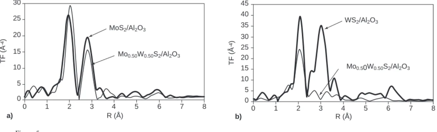
Figure 5 displays the FT’s of the EXAFS spectra recorded at the Mo K-edge (Fig. 5a) and at the W LIII-edge (Fig. 5b) for the MoS2/Al2O3, Mo0.5W0.5S2/Al2O3 and WS2/Al2O3 undoped sulfides. The first peak of the FT corresponds to the expected anionic surrounding of the cations and is fairly reproduced with ≈6 sulfur neighbors at a distance R ≈2.40 Å.
At the Mo K-edge, the intensity of the second peak of the FT (contribution of the cation neighbours), does not decrease a lot from MoS2/Al2O3to Mo0.5W0.5S2/Al2O3. This is con-trary to what was observed for the unsupported Mo(1-x)WxS2 sulfides, for the supported Mo(1-x)WxS2sulfides, the simple observation of the FT thus does not evidence the existence of an intralayer Mo0.5W0.5S2solid solution and rather suggests presence of [MoS2] layers.
However, the aspect of the cationic environment signal observed on the FT obtained for Mo0.5W0.5S2/Al2O3 at the W LIII-edge is rather different: it is split into two peaks. This splitting can be related to the coexistence of a W-W
contribution and a W-Mo one. Effectively, W-W and W-Mo signals have nearly opposite phases so that the corresponding peak positions are different despite the nearly identical cation-cation distances in MoS2 and WS2 (3.16 A). The W LIII-edge FT thus suggests presence of the heterocationic layers of the intralayer solid solution.
Coming back to the Mo K-edge, refinement of the EXAFS spectrum of MoS2/Al2O3 (Table 5) shows that the
cationic in-plane environment of molybdenum contains only molybdenum, as expected. However, the refined neighbour number (N(Mo) = 3.5) is significantly lower than in the case of the massic samples (N≈6). This reduction does not reflect effective reduction of the neighbour number: it can be related to the high dispersion of the active sulfide phase on the support [14] which leads to under estimation of the number of cationic neighbours due to static disorder effects (similar reduction of the neighbour cation number, with similar origin, will be evidenced for all our supported samples). Considering now Mo0.5W0.5S2/Al2O3, calculations were undertaken first on the basis of homocationic [MoS2] layers, in agreement with what deduced from the FT’s. Simple calculation using the parameters N(Mo) and d(Mo-Mo) refined for the MoS2/Al2O3sample leads to a simulated FT 787 R (Å) a) Mo0.50W0.50S2/Al2O3 MoS2/Al2O3 4 6 7 8 3 2 5 0 10 15 20 25 30 1 0 TF ( Å -4) 5 R (Å) b) Mo0.50W0.50S2/Al2O3 WS2/Al2O3 4 6 7 8 3 2 5 0 20 30 35 40 45 1 0 TF ( Å -4) 5 10 15 25 Figure 5
a) Fourier transforms obtained at the Mo K-edge for MoS2/Al2O3and W0.50Mo0.50S2/Al2O3; b) Fourier transforms obtained at the W LIII-edge for WS2/Al2O3and W0.50Mo0.50S2/Al2O3.
TABLE 5
EXAFS refinement results (Mo K-edge): characteristics of the cationic in-plane environment of molybdenum in alumina-supported MoS2and W0.50Mo0.50S2
Mo shell W shell R(Mo) N(Mo) ⌡ 2.10+3 ∆E 0 R(W) N(W) ⌡2.10+3 ∆E0 (Å) (Å2) (eV) (Å) (Å2) (eV) MoS2/Al2O3 3.15 3.5 3.4 1.0 – – – – Mo0.50W0.50S2/Al2O3 3.15 2.2 2.7 15.0 3.16 1.2 2.7 18.8 ∆R = +/–4.10–3Å, ∆N = +/–0.3, ∆(∆Eo) = +/–0.7 eV, ∆(⌡2) = +/–0.6.10–3Å2.
imaginary part completely different from the experimental one. The parameters were then refined but the results of this refinement are not consistent (d(Mo-Mo) = 3.10 Å, N(Mo) = 1.8) with the MoS2structure. The only solution was then to introduce both molybdenum and tungsten as molybdenum neighbours. Under these conditions, correct reproduction of the experimental signal was achieved with N(Mo) = 2.2 and N(W) = 1.2, in reasonable agreement with the nominal formula. In fact, the contribution of the W neighbours can be seen in the Fourier-filtered EXAFS spectrum of the Mo0.5W0.5S2/Al2O3 sample as compared to that of the MoS2/Al2O3 one in the range of 10 to 12 Å–1
as shown in Figure 6. In this case too, the structural arrangement thus corresponds to the intralayer solid solution. This highlights the danger of drawing premature conclusions on the only basis of FT observation.
At the W LIII-edge (Table 6), tungsten is found to be surrounded by 4.3 tungsten neighbours in WS2/Al2O3while, in Mo0.5W0.5S2/Al2O3, its cationic in-plane environment contains both molybdenum and tungsten in relative amounts
(N(Mo) = 2.0 and N(W) = 2.6) consistent with the formula, which confirms the existence of the heterocationic layers of the solid solution.
The FT’s of the EXAFS spectra recorded at the Mo K-edge for the promoted NiMoS2/Al2O3and NiMo0.5W0.5S2/Al2O3 catalysts are given Figure 7. The intensity of the second peak is this time significantly reduced from the former to the latter which suggests that, in NiMo0.5W0.5S2/Al2O3, every layer contains both molybdenum and tungsten. The EXAFS spectra refinements (Table 7) confirm the heterocationic nature of the layers (N(Mo) = 2.9, N(W) = 1.6). The Fourier-filtered EXAFS spectrum of the NiMo0.5W0.5S2/Al2O3 sample fitted with a model Moabs-S-(Mo,W) is given Figure 8. As in the case of unpromoted systems, the presence of W neighbours is clearly seen in the range of 1.0 to 1.2 nm–1. The similarity of the experimental and
fitted spectra confirms the validity of the model used. Consequently, the presence of the nickel promoter does not disrupt the formation of the intralayer MoxW(1-w)S2 solid solution. k (Å-1) 8 12 14 6 4 Im TF inv Fitting 2 -10 -15 5 15 k -3χ (k) 10 -5 0 10 k (Å-1) 8 12 16 6 4 Im TF inv Fitting 2 -10 -15 5 15 k -3χ (k) 10 -5 0 10 14 Figure 6
Fourier-filtered EXAFS k3.χ(k) spectra (diamonds, fitting: solid curve) of MoS2on alumina (left) and that of the Mo0.50W0.5S2supported on alumina sample (right) fitted with a model Moabs-(S,Mo,W)backscatters.
TABLE 6
EXAFS refinement results (W LIII-edge): characteristics of the cationic in-plane environment of molybdenum in alumina-supported WS2and W0.50Mo0.50S2 Mo shell W shell R(Mo) N(Mo) ⌡ 2.10+3 ∆E 0 R(W) N(W) ⌡2.10+3 ∆E0 (Å) (Å2) (eV) (Å) (Å2) (eV) WS2/ Al2O3 – – – – 3.15 4.3 1.8 7.9 Mo0.50W0.50S2/ Al2O3 3.18 2.0 4.0 14.0 3.16 2.6 3.7 6.8 ∆R = +/–4.10–3Å, ∆N = +/–0.3, ∆(∆Eo) = +/–0.7 eV, ∆(⌡2) = +/–0.6.10–3Å2.
C Thomazeau et al. / EXAFS Characterization of New Active Phases for Catalytic Hydrotreatment
Figure 7
Fourier transforms obtained at the Mo K-edge for Ni-MoS2/Al2O3and Ni-W0.50Mo0.50S2/Al2O3.
Figure 8
Mo K-edge Fourier-filtered EXAFS k3.χ(k) spectrum
(dia-monds) of Ni-W0.50Mo0.50S2/Al2O3fitted with three neighbour shells: Moabs-S, Moabs-Mo, and Moabs-W (solid curve).
CONCLUSIONS
The present study illustrates the unique capability of EXAFS for the determination of complex nanoscale structures such
as that of MoxW(1-x)S2-related catalytic systems. Even if the interatomic distances are very close in the MoS2 and WS2 partners, backscattering amplitudes and phase shifts can un-ambiguously clarify the nature of the cationic neighbours of the absorbing atom and allow the presence of the intralayer solid solution to be demonstrated in dispersed unsupported, supported, and Ni-promoted MoxW(1-x)S2catalysts.
ACKNOWLEDGEMENTS
We thank the Lure committee for providing machine-time. C. Thomazeau thanks IFP and CNRS for financial support.
REFERENCES
1 Off. J. Eur. Commun., L350, 58, (1998).
2 Chianelli, R.R., Daage, M. and Ledoux, M.J. (1994) Fun-damental Studies of Transition-Metal Sulfide Catalytic Materials. Adv. Catal., 40, 177-232.
3 Norskov, J.K., Clausen, B.S. and Topsoe, H. (1992) Under-standing the Trends in the Hydrodesulfurization Activity of the Transition Metal Sulfides. Catal. Lett., 13, 1-8.
4 Toulhoat, H., Raybaud, P., Kasztelan, S., Kresse, G. and Hafner, J. (1999) Transition Metals to Sulfur Binding Energies Relationship to Catalytic Activities in HDS: Back to Sabatier with First Principle Calculations. Catalysis Today, 50, 629-636.
5 Hülliger, F. (1976) In: Structural Chemistry of Layered-Type
Phases, Eds Levy.
6 Gaborit, V., Allali, N., Danot, M., Geantet, C., Cattenot, M., Breysse, M. and Diehl, F. (2003) Hydrotreating Properties of Mixed NbxMo1–xS2alumina supported catalysts. Catalysis
Today, 78, 499-505.
7 Thomazeau, C., Geantet, C., Lacroix, M., Harlé, V., Benazeth, S., Marhic, C., and Danot, M. (2001) Two Cation Disulfide Layers in the WxMo(1-x)S2Lamellar Solid Solution.
J. Solid State Chem., 160, 147-155.
8 Breysse, M., Fréty, R., Lacroix, M. and Vrinat, M. (1984) Comparison of the Catalytic Properties in Hydro-desulfurization Reaction of Unsupported MoS2 and WS2 Catalysts: Influence of Surface Areas. React. Kinet. Catal.
Lett., 26 (1-2), 97.
9 Ramanathan, K. and Weller, S.W. (1985) Characterization of Tungsten Sulfide Catalysts. J. Catal., 95, 249-259.
Alonso, G., Valle, M.D., Cruz, J., Petranovskii, V., Licea-Claverie, A. and Fuentes, S. (1998) Preparation of MoS2 k (Å-1) 10 14 6 4 Im TF inv Fitting 2 -10 -15 5 15 k -3χ (k) 8 -5 0 10 12 R (Å) Ni-Mo0.5W0.5/Al2O3 Ni-Mo/Al2O3 4 6 7 8 3 2 5 0 10 15 20 25 35 1 0 TF ( Å -4) 5 30 789 TABLE 7
EXAFS refinement results (Mo K-edge): characteristics of the cationic in-plane environment of molybdenum in alumina-supported Ni-MoS2and Ni-W0.50Mo0.50S2
Mo shell W shell R(Mo) N(Mo) ⌡ 2.10+3 ∆E 0 R(W) N(W) ⌡2.10+3 ∆E0 (Å) (Å2) (eV) (Å) (Å2) (eV) Ni-MoS2/Al2O3 3.16 3.3 1.2 2.2 – – – – Ni-Mo0.50W0.50S2/Al2O3 3.16 2.9 2.0 1.3 3.15 1.6 2.0 –1.7 ∆R = +/–4.10–3Å, ∆N = +/–0.3, ∆(∆Eo) = +/–0.7 eV, ∆(⌡2) = +/–0.6.10–3Å2.
Catalysts by in situ Decomposition of Tetraalkylammonium Thiomolybdates. Catalysis Today, 43, 117-122.
10 Diemann, E. and Müller, A. (1973) Thio and Seleno Compounds of the Transition Metals with the d0 Config-uration. Coord. Chem. Rev., 10, 79-122.
11 Charlot, G. (1958) In: L’analyse quantitative et les réactions
en solution, Eds Masson; Carrier, X., Thèse Université
Paris VI (1998).
12 Aberdam, D. (1998) SEDEM, a Software Package for EXAFS Data Extraction and Modelling. J. Synchrotron Rad., 5, 1287-1297.
13 Rehr, J.J., Zabinsky, S.I. and Albers, R.C. (1992) High-Order Multiple-Scattering Calculations of X-Ray-Absorption Fine Structure. Phys. Rev. Letters, 69, 3397.
14 Shimada, H., Matsubayashi, N., Sato, T., Yoshimura, Y. Imamura, M., Kameoka, T. and Nishijima, A. (1993) EXAFS Study on the Dispersion of Molybdenum Sulfide Catalysts on Gamma-Al2O3. Catal. Lett., 20, 81.
Final manuscript received in May 2005
Copyright © 2005 Institut français du pétrole
Permission to make digital or hard copies of part or all of this work for personal or classroom use is granted without fee provided that copies are not made or distributed for profit or commercial advantage and that copies bear this notice and the full citation on the first page. Copyrights for components of this work owned by others than IFP must be honored. Abstracting with credit is permitted. To copy otherwise, to republish, to post on servers, or to redistribute to lists, requires prior specific permission and/or a fee. Request permission from Documentation, Institut français du pétrole, fax. +33 1 47 52 70 78, or revueogst@ifp.fr.