HAL Id: hal-00945428
https://hal.archives-ouvertes.fr/hal-00945428
Submitted on 12 Feb 2014
HAL is a multi-disciplinary open access
archive for the deposit and dissemination of
sci-entific research documents, whether they are
pub-lished or not. The documents may come from
L’archive ouverte pluridisciplinaire HAL, est
destinée au dépôt et à la diffusion de documents
scientifiques de niveau recherche, publiés ou non,
émanant des établissements d’enseignement et de
bCMS-SPL case study: A proposition based on the
Cloud Component Approach
Jean-Baptiste Lezoray, An Phung Khac, Antoine Beugnard
To cite this version:
Jean-Baptiste Lezoray, An Phung Khac, Antoine Beugnard. bCMS-SPL case study: A proposition
based on the Cloud Component Approach. MODELS 2011 : Workshop Comparing Modeling
Ap-proaches, Oct 2011, Wellington, Nouvelle-Zélande. 21 p. �hal-00945428�
bCMS-SPL case study:
A proposition based on the Cloud Component Approach.
Jean-Baptiste L´
ezoray, An Phung-Khac, and Antoine Beugnard
TELECOM Bretagne, D´
epartement Informatique
Technopˆ
ole Brest-Iroise - CS 83818 - 29238 Brest Cedex 3
{jb.lezoray, an.phungkhac, Antoine.Beugnard}@telecom-bretagne.eu
August 5, 2011
Contents
1 Introduction 2
2 Cloud Component Metamodel 2
2.1 Basic concepts . . . 2
2.2 Sectors on cloud components . . . 3
2.3 Composite cloud components . . . 4
2.4 Types of bindings . . . 5
2.5 The CC metamodel . . . 5
2.6 Example: The Generic Data Transmitter CC. . . 6
3 Model for Variable Refinement Processes (MVRP) 7 3.1 MVRP . . . 7
3.2 Features implementation . . . 8
4 Modeling the bCMS-SPL using CCs and MVRPs 9 4.1 bCrash System . . . 9
4.2 Common Coordinator Process . . . 11
4.3 Station Coordinator Process . . . 11
4.4 Information aggregator . . . 11 4.5 Others . . . 12 4.6 Variations . . . 12 5 Conclusion 13 Appendices 15 Abstract
This paper is a model for the Comparing Modeling Approaches workshop. It presents the cloud component model and a Model for Variability of Refinement Processes used to model the proposed use case [1, 2]. Our targets are high-level and architectural design, and
evolution. Runtime support will be tackled, but is not in the main focus of our paper. We introduce:
• A single system: on the basis of a custom component model, the cloud component model. The latter is dedicated to the modeling of distributed applications [1]. • The whole SPL: on the basis of an MDE refinement process model that has the
prop-erty of being variable. Its specification is inspired by previous works on refinement and feature models dedicated to provide adaptation capabilities to component-based architectures [2].
1
Introduction
This paper presents an interpretation of the bCMS-SPL use case. Our approach for modeling Software Product Lines (SPL) is based on Component Based Software Engineering (CBSE), Model Driven Architecture (MDA), and model trans.
We provide a development process for adaptive distributed components. From the architec-tural point of view, we rely on cloud components for modeling the software. A cloud component (CC) is a distributed component where the main idea is that CCs hold the distribution, on the contrary of bindings which are made local to a node. This reversal of the pattern commonly used for components for distribution – distributed bindings and local components – raises some interesting properties. For instance, it hides the distribution-specific properties that are usually delegated to bindings inside the component (QoS, deployment, security, protocols). Thereby, those properties become non-functional properties of the component [1].
From the development process point of view, we combine SPL and MDA using a Model of Variable Refinement Processes (MVRP), that is inspired by Feature Models. The feature mod-eling method is used for the separation of functional concerns. Each concern is a variation point and alternative solutions to this concern are variations. In MVRP, concerns are implemented using model transformations. Therefore, to build a system variant corresponding to a feature configuration, the base model of the system is step by step transformed from a high abstraction level to the implementation level. Each transformation is compliant with the MDA pattern, i.e. a concern-independent model is transformed into a concern-specific model.
The Section 2 presents the CC metamodel. Section 3 discusses the Model for Variable Refine-ment Processes we used to model the bCMS-SPL. Finally, sections 4 and 5 respectively present the modeling of the bCMS-SPL using CCs and MVRP, and conclude the proposition. The complete models for bCMS-SPL are available in the appendices.
2
Cloud Component Metamodel
This section provides details about the three most fundamental notions involved in CCs: border, sectors, and connectors.
2.1
Basic concepts
A CC model is a component model for distributed systems [1]. In fig.1, we present the central concept behind CC models. Traditionally, components are localized and bindings hold the dis-tribution. The left part of fig.1 represents this case, component A is a client of component B. Components A and B are both deployed in specific locations and the binding is the glue between those components, implemented for instance using web services or any other binding protocol. Two CCs are depicted in the right part of fig.1. Unlike the common scheme, CCs are distributed
and bindings are local. To distinguish cloud components with “common” ones, we represent them with an ellipse shape in the graphical model instead of the common rectangle shape.
Szyperski gives a well recognized definition of a component as “a unit of composition with contractually specified interfaces and explicit context dependancies only. A software component can be deployed independently and is subject to composition by third parties” [3, p.41]. Despite an original view of the distribution side, components modeled as CC are fully compliant with this definition, and are therefore components.
component A component B
Local Distributed
Local
cc. A cc. B
Distributed Local Distributed
Figure 1: Distribution of components and bindings in common components (left) versus in CCs (right).
The border of a CC is the part of the architectural specification that is accessible to the final user of the component, on the contrary to the internal architecture which is hidden by the border. From an internal architecture point of view, CCs are composite components. They are build on top of other components, being cloud or common components, that are deployed on some of its sectors. These components are linked with each others on the basis of connectors that follow specific rules.
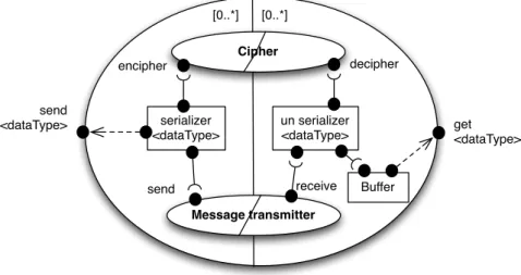
The reader may refer to fig.2 throughout the reading of this section, as it presents a sample complete architecture for a cloud component that is part of our implementation of the bCMS System. Its purpose is to implement an inter-sector communication service. It transmits messages from one point of the architecture to another: from send<dataType> interfaces to get<dataType> ones. Inner components of this CC will be detailed in section 2.6.
[0..*] [0..*] get <dataType> send <dataType> Buffer serializer <dataType> un serializer <dataType> Cipher encipher decipher Message transmitter send receive
2.2
Sectors on cloud components
CCs can be divided in sectors. Sectors are part of the specification of the border of CCs, as well as interfaces. A sector denotes a location in a CC. It is similar to the UML concept of node, and roughly corresponds to physical devices.
Each sector is associated with a multiplicity within [n..m] with n ≤ m, n ∈ N and m ∈ N∗. When deployed, each sector from a CC has a cardinality property that describes how many times it was deployed to specific locations. The multiplicity is a range in terms of valid cardinalities, and sectors cardinalities must observe this range. If a single cardinality does not fulfill its multiplicity, then the whole CC is said to be in an inconsistent or unstable state, and may fail to render the services for some of its interfaces. Despite being close concepts, the cardinality property is not directly linked to the notion of “instantiating objects”: it rather corresponds to the capability of having multiple copies of a sector at the same time in a single CC. We consider that this “duplication” is a deployment issue as it simply brings a sector to a specific location, which is somehow different of object’s instanciations. That said, for the seek of simplicity and clarity, we will refer to this duplication property as “instanciations”.
Each interface is assigned to a sector, and each sector may hold zero, one, or more interfaces. During deployment, sectors duplicate each interface so that each one is accessible from multiple locations.
On the Data Transmitter CC (fig.3), two sectors are defined. Their multiplicity of [0..∗] suggests that their respective interfaces, send<dataType> and get<dataType>, may be accessible from an unconstrained number of locations.
[0..*] [0..*] get <dataType> send <dataType>
Figure 3: Border of the generic Data Transmitter CC.
2.3
Composite cloud components
The composite term refers to a strong aggregation relation, where parts are owned by a single composite, and their life cycle depends on the composite one. CCs are always composite: they encompass sub-components that can be either CCs (also composite) or common components (either primitive or composite). On the contrary, a common component may embed another component but cannot embed a CC. Composition of CCs must observe several rules. Composite CCs behave differently from composite common components. We will not dwell on the composite common components case as it behaves like in any other hierarchical component model. When being embedded in a composite CC, CCs and common components are not equivalent. Common components are assigned to a single sector, but this constraint does not apply for CCs: it can be in between sectors of the composite. In both cases, the border of the composite hides them completely, and their life cycle depends on that of the composite. Embedded CCs are not part of the border specification of the composite, and are then considered as implementation-related issues. Embedded CCs must observe the multiplicities of the sectors of the composite. In other words, the whole set of interfaces of a sector must be assigned to strictly one sector of the composite. These sectors matching rules are based on the fact that a sector from an embedded CC is instantiated exactly as many times as the composite one: its multiplicity should support the multiplicity of the composite’s sector. fig.4 presents valid and invalid sector matchings. This
rule can be formalized as follows:
General rule: A sector A with a multiplicity of [nA..mA] can be embedded in a sector B with
a multiplicity of [nB..mB] iff nA≤ nB and mA≥ mB.
[0..1] [0..*]
[0..1] [0..3] [1..1] [0..2] [0..*] [0..1] [0..1] [1..1] [0..*] [0..*]
Figure 4: Valid and invalid embedded sector matchings.
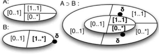
When an embedded CC does not match the sectors of the composite, some of its sectors can be duplicated. The set of interfaces are duplicated along with the sector. A duplication does not affect the border, and a CC with duplicated sectors is strictly equivalent to the original one although its representation is different. The fig.5 presents a sector duplication. A cloud component B is to be embedded in a cloud component A. Sectors of B do not match A ones: The [0..1] from B matches [0..1] from A, but [1..∗] from B must be duplicated to match with both [1..1] and [0..∗] from A. The result of the duplication is two sectors with the same multiplicity than A. The reader should notice that i) the δ interface has been duplicated along with the sector and is then available in two sectors of A, ii) the duplication do not affect B’s border which is equivalent to the unduplicated one from a conceptual point of view, and iii) other solutions may exist to embed B in A. The general rule for duplicating [n..m] sectors is as follows:
General rule: A sector with a multiplicity of [n..m] can be duplicated in two sectors with cardinalities of [n′..m′] and [n′′..m′′], iff n′+ n′′≤ n and m′+ m′′≤ m.
[0..1] [1..*] [0..1] [0..*] [1..1] [0..1] [0..*] [1..1] δ δ δ A: B: A ⊃ B : [0..1] [0..*] [1..1]
Figure 5: Sector duplication.
2.4
Types of bindings
Composite CCs are built on top of two types of bindings: the promote interface binding, and the functional interface binding. The interface promotion binding is the promotion of either the interface of a component or of a CC to the border of the composite. The graphical representation for this type of binding is a dashed arrow (see fig.2). The functional interface binding is the connection of two compatible interfaces including a required one and a provided one. The graphical representation is a line with a semicircle on the ’provided’ side (see fig.2). By definition, both those bindings cannot cross any border. All promote interface bindings and functional interface bindings must have their both ends in a single sector.
2.5
The CC metamodel
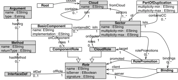
The fig.6 presents the CC metamodel. Greyed elements correspond to meta elements involved in the modeling of the border of the CC.
isIn 1 containsCC 0..* hasArg 0..* itfDef 0..1 hasMethod 0..* name: EString implementation : EString BasicComponent name : EString Cloud name : EString isServer : EBoolean signature : EString Role CloudRole roles 0..* roles 0..* sectors 1..* containsBC 0..* Binding RolePromotion bindings 0..* rolePromotions 0..* name : EString multiplicity-min : EString multiplicity-max : EString Sector onSector 1 client 1 server 1 promoted 1 target 1 fromCloud 1 onComponent 1 ComponentRole IsIn 1 isIn 1 contains 0..* Root clouds * multiplicity-min : EString multiplicity-max : EString PartOfDuplication of 1 name : EString returnType : EString Method name : EString type : Estring Argument InterfaceDef ofRole1
Figure 6: The CC metamodel.
2.6
Example: The Generic Data Transmitter CC.
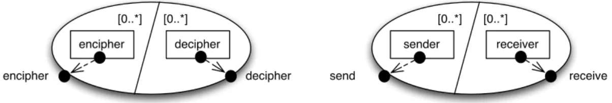
In the sample architectural specification of the generic Data Transmitter CC depicted in fig.2, the two types of sub-components are depicted: common components (serializer<dataType>, unserializer<dataType>, Buffer), and cloud components (Cipher and Message Transmitter). The specification of the sub-CCs are depicted in fig.7. These two CCs, Cipher and Message Transmitter, are similar because they both do not include any sub-CCs. However, they are very different in their spirit. The Cipher CC does not include any communication. It is a logical aggregation of the cipherer and decipherer, that by definition should not communicate with each other. This logical aggregation expresses that the elements are linked together. For instance, the adaptation of one implies the adaptation of the other. On the other hand, in the Message transmitter CC, the communication between the sectors is based on a broadcast of each mes-sage received by mesmes-sage senders to each mesmes-sage receiver. The way mesmes-sages are routed between these components is not represented, and therefore depends on the implementation of Message Sender and Message Receiver components. Of course, a configuration of the communication is necessary for both those components, but it is not part of the model.
3
Model for Variable Refinement Processes (MVRP)
To model the bCMS product line, we rely on a model of refinement processes, that has the property of being variable: the Model for Variable Refinement Processes (MVRP). Its syntax is based on the syntax of Feature Models (FM) defined by Czarnecki [4]. However, its semantic slightly changes to represent the fact that MVRP features are model refinements. The latter property implies major differences on the semantic of features and configurations.
encipher decipher encipher decipher [0..*] [0..*] send receive sender receiver [0..*] [0..*]
Figure 7: The cipher CC (left) and the message transmitter CC (right)
MVRP models are based on our previous work on a feature model implementation that describes hierarchies of component-based architectures using feature models, in order to provide dynamic adaptation capabilities [2].
3.1
MVRP
MVRPs are dedicated to CC models1. Each CC is associated with an MVRP model that defines
some architectural variants of it, on the basis of a set of refinement processes. Indeed, each feature of an MVRP is implemented using a model transformation, and thus is a part of the refinement of the architecture. Moreover, an MVRP also includes solutions, which are parameters for features. A solution is equivalent to advices in Aspect-Oriented Modeling approaches. The question of the implementation of each feature with a model transformation will be tackled in section 3.2.
The root feature introduces the border of the CC, including its sectors and its interfaces. Other features introduce architectural elements that are considered as nonfunctional from the final CC user point-of-view. In other words, sub-sequent features do not modify the border of the CC (unless explicitly, as explained bellow). This consideration is important as it implies that all the sub-sequent variants are compliant with the border of the CC.
Configurations of MVRPs can be chosen by a designer, similarly as for FMs. A configuration represents a set of choices in the variation points offered by the MVRP. When a configuration is chosen from an MVRP, the selected set of features represents a sequence of transformations, that, when being executed, produces an architectural variant of the CC. We base our approach on the staggedconfiguration as described by Czarnecki [4]: features can get a multiplicity in MVRP. The MVRP undergoes a first refinement stage when it is added to a composite. This first stage configures all the features that have an influence on the border definition. Those features can be identified by an affect link, which is described thereafter.
A set of refinements is not a simple juxtaposition of features. Indeed, when a feature gets refined by another one, it can naturally loose some of its functional and nonfunctional properties. This is a major difference with FMs as the features of an FM must be independent. Keeping the independency of features when configuring an FM is a major problem, which is known as the feature interaction problem [5]. With MVRP, it is natural from the designer point of view that a feature may affect other ones, as the selection of a feature in a configuration naturally leads to a modification of the architecture. Moreover, we also consider that the selection of some configurations is done by the designer at the same time than specification and generation. Indeed, feature interactions can be monitored in each step of the configuration. This particularity limits the number of available variants from an MVRP, but increases the designer control over what is
1They may be applicable to other metamodels of architecture, but we have not yet studied how they might
generated with the processes, and also resolves problems on point-cut specifications (not detailed here).
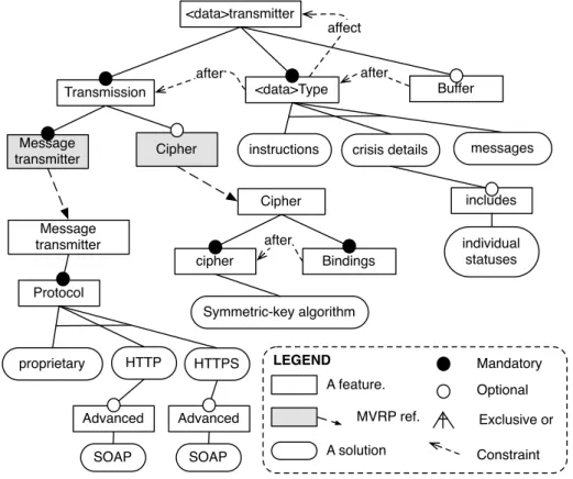
The fig.8 presents an example of MVRP for the Message Transmitter CC and its sub-CCs. The <data>transmitter, Message transmitter, and Cipher are the roots of three MVRPs. They are linked with each other using MVRP references, which are similar to FM references [4]. During the configuration of the CC, the MVRP references are unfolded, and are made part of the configuration.
<data>transmitter
Transmission
Cipher
<data>Type Buffer
instructions crisis details
individual statuses includes cipher Symmetric-key algorithm Cipher Bindings Message transmitter after Protocol proprietary HTTPS SOAP Advanced Message transmitter after after messages affect MVRP ref. A feature. LEGEND A solution Mandatory Optional Exclusive or Constraint HTTP SOAP Advanced
Figure 8: Model of Variable Refinement Process (MVRP) for the generic Message Transmitter CC.
There are some constraints defined on MVRP models that express a sequential ordering on the execution of the features. The after constraint is one of them. When an after constraint is defined between two features, it indicates that the feature at the source of it must be executed after the feature of its target. It can be because it needs some of its elements at that point for the definition of a point-cut, to reuse or transform them. Another type of constraints is defined in MVRP models: the affect constraints. The target of affect constraints is always its direct root feature of the MVRP. An affect constraint expresses that the border of the component is modified by the transformation that implements the feature: multiplicities, sectors, interfaces... Then, when it is encompassed in a CC, its border may be modified to match the needs of the composite one.
3.2
Features implementation
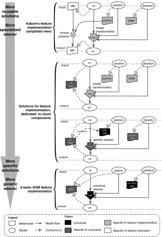
We base our approach for the implementation of features for MVRP and CCs on previous works in our team [7]. As depicted in fig.9, the approach of those previous works (on top of the figure) contrasted with AOM approaches (on bottom of the figure). With AOM, all the flexibility is in the advice and in the point-cut definitions, as the weaver is universal. On the other hand, with this approach, the designer first designs the solution metamodel and then creates a model transformation that injects this concern in the base model. Then, the flexibility is both in the solution model and in the transformation: the solution becomes highly reusable [6]. The price for this high flexibility and reusability is that it requires an important engineering time to implement the features.
To implement the features for MVRP and CCs, we choose intermediate approaches. We base the approach on two feature schemes. Each feature may be implemented in the one or the other. First, we dedicate our features to MVRPs and CCs. This way, we simplify features implementation by not requiring any sort of human activity during the specification of the feature implementation. Second, we still separate the solution implementation metamodel and the base metamodel. This implies that the solution of each feature is expressed in a metamodel that is different from the base metamodel, unlike classical AOM approaches, and keeps its reusability.
4
Modeling the bCMS-SPL using CCs and MVRPs
The bCMS-SPL system modeled using CCs and MVRPs is presented in the appendices. It consists in the description of four MVRPs. Each MVRP is associated with a sample CC, that results of a configuration of the MVRP. The four MVRPs are the followings:
• the bCrashCC System CC (fig.10, fig.11),
• the common Coordinator Process CC (fig.12, fig.13), • the Station Coordinator Process CC (fig.14, fig.15), • the information aggregator CC (fig.16, fig.17).
4.1
bCrash System
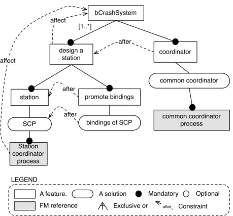
The bCrash System CC (fig.10, fig.11) is the main component of our model for the bCMS system. It represents a whole bCMS System architecture. The root feature of the bCrash System introduces the border of the CC: its interfaces (Station GUI, GPS GUI, hand held device GUI) and sectors (with multiplicities of [1..1], [0..∗] and [0..∗]). The sectors describe respectively a station (either a police station or a fire station), a GPS device in a vehicle (either a police car or a fire truck), and a hand held device for an individual (either police man or firemen). The MVRP is composed of two sub-features:
The first one, “design a station”, is a composite feature that aims at introducing a station in the MVRP. During the configuration of this MVRP, a partial configuration of this feature is proceeded each time a station has to be introduced in the system [4]. This partial configuration results in a new feature with a [1..1] multiplicity. Each time this feature is executed as a model transformation, it adds three sectors to the CC, resulting in a new station to be introduced in the system. The border is modified by this addition, so affect constraint is then specified from the “design a station” feature to the root feature. The “station feature” and its single solution “SCP” introduces a “station coordinator process” in between each sectors of the station, and
Tm cc cc' cc MM (input) (output) Metamodel Model Model flow
Conforms to Specific to a process
Specific to feature implementation
Specific to feature execution
Colors UW m m' advice MM (input) (output) pointcut
A basic AOM feature implementation pointcut MM universal weaver model transformation cc cc' (input) (output) generic weaver
Solutions for feature implementation, dedicated to cloud components sol(Tm) solution decision solution transfor transfor. DSL GW Universal More reusable solutions More specialized weaver More specific solutions More generic weaver DMM UML MM cc MM <<use>> MM' Tm m m' sol(Tm) solution MM (input) (output) model transformation DMM decision human process Legend Kaboré's feature implementation (simplified view)
the “promote bindings” promotes the interfaces of this component to the global one (see fig.11). The introduction of the Station Coordinator Process may also affect the bCrash system’s border, when it has to add an interface to communicate with vehicles that are not in his scope (e.g., citizen vehicles).
The second sub-feature of the root feature, “coordinator”, introduces a “common coordinator process CC” in between each station sector of the architecture. This component is composed of a single sector, but the latter is duplicated to match the number of station sectors of the bCrash System. This CC, its functionalities and its MVRP are described in details thereafter.
4.2
Common Coordinator Process
The Common Coordinator Process CC (fig.12, fig.13) is a component that enables an inter-station communication. The data it transmits are “crisis details”, this is why it is based on a “message transmitter CC” with the “crisis details” feature selected (see fig.8), as this selection determines the data type held by the “Message Transmitter component”. The reader may note that this “Common Coordinator Process CC” does not hold any variation, and there is only one refinement process that corresponds to its MVRP. However, as it embeds a “message transmitter CC”, it inherits its variations and thus there are still some variants for it.
4.3
Station Coordinator Process
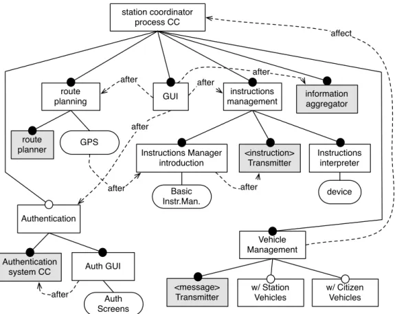
The Station Coordinator Process CC (fig.14, fig.15) describes the architecture for a single station, that can be either a police station or a fire station. Thus the CC includes several components such as :
• A route planner CC, in charge of computing and transmitting routes to vehicle GPS devices. • An information aggregator CC, that collects information for each station and manages a coordination with other stations. This CC is described in details bellow. One of its sectors was duplicated to match both the individuals and the vehicles sectors.
• A data transmitter CC, that is another variant for the “generic Message Transmitter CC”. • An authentication system CC, that provides authentication capabilities to identify the
station users and individuals (either police officers or firemen) of the system.
• An instructions manager is a common component that is in charge of preparing and sending instructions to individuals as well as GPS coordinates to vehicles to go to the crash place. It is under control of the station coordinator agent (via the “GUI” element).
• Other components includes: GUI, Auth Screen, GPS, and device.
On the MVRP side, there are not many variations in it, except on the authentication which is optional, and on the types of communications that are allowed (with station vehicles and/or citizen vehicles). The latter may affect the border of this CC by adding interfaces to communicate with other stations vehicles, or with citizen vehicles, that both are not actors in the scope of the Station Coordinator Process CC. This case is not represented in the figure.
4.4
Information aggregator
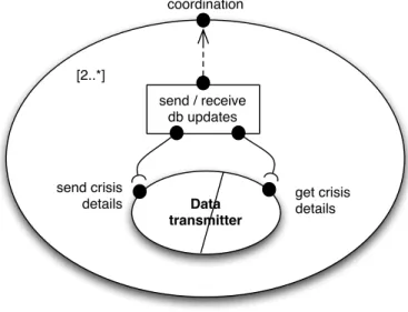
The information aggregator CC (fig.16, fig.17) is the CC where details on the crisis are stored. It includes a database component (“DB”) to store crisis details, two components to update and
access the database (“DB updater” and “DB access”), a message transmitter to collect database update transactions from either individuals or vehicles, and a coordinator which is a daemon that forwards every update in the DB to any other stations. It is interesting to note that, from the border point of view, the localization of the data managed by the information aggregator is not important, and for instance could have been replicated on each client sector.
4.5
Others
We previously presented the following CCs and their MVRP, so we will not elaborate any more on them:
• the generic message transmitter CC (fig.8, fig.2), • the cipher CC (fig.8, fig.7),
• the Message Transmitter CC (fig.8, fig.7).
Moreover, for a seek of conciseness, the two following CCs will not be detailed further: • the authentication system CC (fig.18),
• the route planner CC (fig.18).
However their architecture follows a similar scheme as the ones previously presented
4.6
Variations
In this section, we will comment on how each variation is handled using the model.
(7.1) Police and Fire Stations multiplicity. The multiplicity of the “design a station” feature of the bCrash System CC can handle this variation during the configuration of the MVRP (see fig.10).
(7.2) Vehicles Management. The management of the possibility of sending to and receiving messages from vehicles is handled in the Station Coordinator Process (fig.14, fig.15), during the configuration of the “vehicle management” feature. Moreover, as a Station Coordinator Process manages a single station, the inter-station vehicles communication and the communication with citizen vehicles is also reified in the bCrash System CC (fig.10, fig.11).
(7.3) Vehicles Management Communication Protocol. The management of this vari-ability is done when configuring each “generic Message Transmitter CC”, by selecting the right features “HTTP”/“HTTPS”/“SOAP” features (see fig.8).
(7.4) Crisis Multiplicity. We are not able to model this variation using our approach because we are modeling architectures. Modeling this variation implies updating primitive components implementations, which case we cannot handle (e.g., in the DB component, or in the coordinator in fig.17).
(7.5) Confidentiality of Data Communication. This variability is handled by selecting the “Cipher” feature in the “generic Message Transmitter CC” (see fig.8). This adds the “Cipher CC”, and creates interfaces on the “serializer” components, and adds the bindings.
(7.6) Authentication of System’s Users. This variability is handled by selecting the op-tional authentication feature in the “Station Coordinator process CC” (see fig.14). This adds the “Authentication System CC”, the two “Auth screen” components, adds the interfaces on the “Gui” and “device” components, and creates the bindings. Here, the variations on the MVRP of the ”Authentication System CC” are not depicted in the model, however it would create variants of the “Authentication System CC”.
(7.7) Communication Layer. This variability is handled by selecting the right “Protocol” feature in the “message Transmitter CC” (see fig.8). This modifies the reference to the imple-mentation of the “sender” and “receiver” components in the “message transmitter CC”, so that it can handle each protocol.
5
Conclusion
This approach has several benefits. The CC model offers the possibility of making logical aggre-gations of distributed component, giving the opportunity to model distributed architectures in a convenient manner. Those logical aggregations ease the specification of nonfunctional properties on communication. The MVRP model offers to the designer the possibility to take advantage of the properties of the underlying component architecture (e.g., a border hides its internals) during the specification of the refinements of the architecture. This properties limits the impact of feature interactions. Moreover, the MVRP model makes feature interactions more explicit by modeling the refinements instead of independent features. The implementation of the features using original model transformations schemes offers the possibility to reuse features solutions (models and metamodels) in numerous situations, and offers more expressivity in to those mod-els as they are not expressed in the base metamodel.
The original goal of our work is to reach runtime reconfiguration of distributed components architectures [2]. At runtime, a variant can be replaced by another one by a reconfiguration platform. This platform, which is also a cloud component, uses information from the variable refinement process to achieve the planning and the execution of the reconfiguration actions.
As our approach is essentially oriented on the architecture level, we were not able to model fine grained situations such as the one described in sections 4 and five of the Requirement Definition Document. However, we plan to study in the near future how feature implementations could be extended by integrating other informations, such as feature models artifacts, adaptation specific information, or the generation of code for primitive components. We believe that our future implementation will be able to handle such fine grained situations.
References
[1] J.-B. L´ezoray, A. Phung-Khac, M.-T. Segarra, J.-M. Gilliot, and A. Beugnard, “Cloud Components: Modeling Cloud-like Architectures”. Submitted on August 2011 to the 26th Symposium On Applied Computing, Software Engineering Track.
[2] A. Phung-Khac. “A model-driven feature-based approach to runtime adaptation of dis-tributed software architectures”. PhD thesis manuscript, Institut T´el´ecom - T´el´ecom Bre-tagne, UR1-UEB, 2010.
[3] C. Szyperski with D. Gruntz, and S. Murer. “Component Software, beyond Object-Oriented Programming”. Addison-Wesley and ACM Press, Second Edition, ISBN 0-201-74572-0, 2002.
[4] K. Czarnecki, S. Helsen, and U. Eisenecker. “Staged configuration using feature models”. SPLC 2004, LNCS 3154, Springer, pp.266?283, 2004.
[5] S. Apel and C. K¨astner. “An Overview of Feature-Oriented Software Development”. Journal of Object Technology (JOT), 8(5):49?84, July 2009.
[6] C.E. Kabor´e, A. Beugnard. “Interests and drawbacks of AOSD compared to MDE. A posi-tion paper”. Proc. of the 3rd WS on Models and Aspects, Handling Crosscutting Concerns in MDSD, 21st European Conference on Object-Oriented Programming, Berlin, Germany, 2007.
[7] C.E. Kabor´e, A. Beugnard. “Implementing a Data Distribution Variant with a Metamodel, Some Models and a Transformation”. Lecture Notes in Computer Science, Volume 5053, Distributed Applications and Interoperable Systems, Pages 224-237, 2008.
[8] “Aspectj, crosscutting Objects for better modularity”, http://www.eclipse.org/aspectj, Last visit on August 2011.
Appendices
bCrashSystem coordinator common coordinator design a station SCP promote bindings station bindings of SCP after after Station coordinator process FM reference A feature. LEGENDA solution Mandatory Optional Exclusive or common coordinator process after Constraint affect [1..*] after affect
Police station Coordinator process Police station Coordinator GUI Police car Police officer police car GPS GUI
Police station police
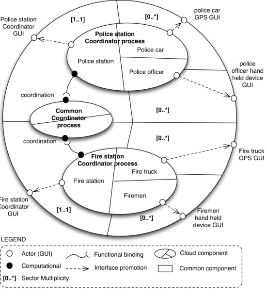
officer hand held device GUI Common Coordinator process coordination coordination [0..*] [0..*] [0..*] [0..*] Firemen hand held device GUI Fire truck GPS GUI Fire station Coordinator GUI Fire station Coordinator process Fire truck Firemen Fire station [1..1] [1..1] LEGEND Actor (GUI) Computational
Functional binding Cloud component Common component Interface promotion
[0..*] Sector Multiplicity
Common coordinator process introduce component send/receive db updates <crisisDetails> transmitter after
Figure 12: MVRP for the common Coordinator Process CC.
[2..*] coordination Data transmitter get crisis details send crisis details send / receive db updates
station coordinator process CC route planner information aggregator <instruction> Transmitter Authentication Basic Instr.Man. Instructions Manager introduction after instructions management route planning GPS after GUI after after after after Authentication
system CC Auth GUI
Auth Screens after Instructions interpreter device Vehicle Management w/ Station Vehicles w/ Citizen Vehicles <message> Transmitter affect
station Coordinator GUI Vehicle individual assistant device car GPS GUI Station [1..1] [0..*] [0..*] individual hand held device GUI coordination w/ other stations route planner push vehicle status set Crash
GPS coord get route plan
Authentication system authenticate manage users data transmitter get instructions send instructions push Crisis details Auth screen GUI Auth screen device GPS Info aggregator instructions manager
access crisis details
authenticate authenticate
Information aggregator CC DB introduction Basic DB <Status/crisisDetails> transmitter after DB coordinator Basic DB coordinator after DB accessor Basic accessor DB updator Basic updator
Figure 16: MVRP for the information aggregator CC.
access crisis details coordination w/ other stations [1..1] [0..*] DB send status / Crisis details get status / Crisis details [0..*] [0..*] Message transmitter send status coordinator DB updator DB access
Route planner [1..*] [0..*] push vehicles statuses set Crash GPS coord get route plan [0..*] [1..1]
auth manage users
Authentication sub-system