HAL Id: hal-01069935
https://hal-ensta-bretagne.archives-ouvertes.fr/hal-01069935
Submitted on 6 Oct 2014
HAL is a multi-disciplinary open access
archive for the deposit and dissemination of
sci-entific research documents, whether they are
pub-lished or not. The documents may come from
teaching and research institutions in France or
abroad, or from public or private research centers.
L’archive ouverte pluridisciplinaire HAL, est
destinée au dépôt et à la diffusion de documents
scientifiques de niveau recherche, publiés ou non,
émanant des établissements d’enseignement et de
recherche français ou étrangers, des laboratoires
publics ou privés.
The disabled set sail
Kevin Bruget, Benoit Clement, Olivier Reynet, Bernt Weber
To cite this version:
Kevin Bruget, Benoit Clement, Olivier Reynet, Bernt Weber. The disabled set sail. CAN Newsletter,
2014, pp.8-13. �hal-01069935�
R
obotics in the sailing field is now a reality as was demonstrated in 2008 at the World Robotic Sail-ing Championship and the associated conference [3]. Able to replace humans during competition or to re-alize autonomous measure-ments, its field of action has become larger than before. Our approach is not to re-move human action, but to assist it during information acquisition, decision pro-cess and execution. Sail-ing globally has remained a field inaccessible for people with a disability, because of the extreme mobility the sailor needs to acquire in-formation and to manipu-late commands of a boat. Sailing requires significant efforts that not all disabled can put forth. We aim to give sailors with a disability ac-cess to those kinds ofactiv-The disabled
set sail
Sailing is not an activity that can easily be done with a handicap.
Sailors typically need mobility to steer a boat. An Arduino-compatible
CAN architecture for sailing applications is set to change that.
Authors Kévin Bruget kevin.bruget@ensta-bretagne.org Benoît Clement benoit.clement@ensta-bretagne.fr Olivier Reynet oliver.reynet@ensta-bretagne.fr Ensta Bretagne
2, Rue Francois Verny FR-29200 Brest Bernt Weber
bernt.weber@splashelec.com Splashelec
18, Rue de Pont Louet FR-29200 Brest
Links
www.ensta-bretagne.fr www.splashelec.com
ities. The assistance system was initially composed of an electronic board and a joy-stick, which allow a person to steer a boat manually as helmsman, forming part of a crew. When needing free hands, the helmsman can activate compass guided steering.
An Android based HMI was developed to com-plete the system with a vi-sual navigational aid for disabled people [2]. To pro-vide a more complete view of the environment for the skipper and to counterbal-ance the lack of mobility, sensors were added to the system. Linked to an Ardu-ino board, information was sent to a tablet in charge of the information display via Bluetooth. Interfacing and cabling became com-plex and interfaces to con-nect extensions became a
rare resource. Users then asked for joystick-steering on smaller single-handed boats, which requires more actuators and sensors. It was time to think about a different system architec-ture, with fewer connections and better reliability.
The present part of the project therefore aims to de-velop a CAN interface board and the necessary software to allow communication us-ing a more modular and flexible network system. This system needed to be easily adaptable to all sorts of situations and disabilities: developers should be able to plug in their own sensors and show data directly on the tablet. On the software side, an Arduino bootload-er compatible with CAN al-lows the programming of nodes directly through the network. The final objective
We aim to give
sailors with a
disability access
to mobile activities.
8
CAN Newsletter 2/2014
A
pp
lic
at
io
n
NEW PRODUCT
• Economical solutions for series applications
• Optimized for industrial applications
• Solutions for stationary and mobile use
• Software support for bus-analysis,
measurement and contro
l
PCIe
CAN Interface CAN InterfaceUSB CAN InterfacePCI-104
Ethernet CAN Interface PC-104 CAN Interface PCI CAN Interface +49-8441-490260 www.ems-wuensche.com Sonnenhang 3 Tel. Fax.
CAN Interfaces for Your Requirements
+49-8441-81860 D-85304 Ilmmünster
safe clean &
economical
Automotive Electronics
Smart and innovative IP solutions
for embedded systems
Bosch off ers a broad portfolio of IP modules for automotive and industrial application. Our certifi ed IP modules are ready for integration, making the perfect adaption of micro-controllers to your needs easy.
The Bosch IP product range includes:
▶ communication controller IPs for CAN, LIN and FlexRay bus
▶ scalable timer modules for fl exible use in multiple domains
Find out more at:
www.bosch-semiconductors.com
Drive Technology \ Drive Automation \ System Integration \ Services
Those who want to move the world
require special drive: SEW-EURODRIVE
SEW-EURODRIVE is one of the leading companies in drive engineering around the world. We have achieved this position by creating an added value for our customers that exceeds the mere product level. The basis for this success is our modular concept. It offers millions of possible combinations based on modular control and drive electronics as well as the respective gearmotors and provides a maximum of versatility at any time. It does not matter if you want to use servo drive systems, industrial gear units or decentralized drive technology in your system. We always have the right solution for you. Then there is another factor that makes SEW-EURODRIVE so successful and represents the difference between good and exceptional: the people working at SEW-EURODRIVE. You will find people with a passion for the world of movement, regardless of whether you are dealing with project planning, implementation or service. SEW-EURODRIVE—Driving the world
SEW-EURODRIVE GmbH & Co KG P.O.Box 30 23
76642 Bruchsal / Germany Phone +49 7251 75-0
is to provide sailors with a navigational assistance system able to perform au-tomated tasks like heeling limitation, autopilot, etc. The system has to integrate the needed adaptability into the development process and to offer a solution for vari-ous kinds of disabilities. For example steering with a joystick compensates the lack of strength in an arm and the HMI centralizes sensor information to com-pensate a lack of mobility and sensitivity to wind and speed. Furthermore, due to its open-source nature, the software system is modi-fiable and developers can add functionality or change the HMI according to specif-ic needs. Finally, the system should be adaptable to ev-ery kind of boat.
Displays and auto-pilots installed on today’s sailing yachts mostly use multi-drop serial networks with vendor specific proprie-tary protocols. On some re-cent boats, the CAN-based NMEA2000 [1] network has replaced the proprietary protocols. For higher band-width requirements such as radar or echo sounder im-ages, these networks are sometimes completed by Ethernet cabling (Furuno
Navnet, Raymarine Seatalk-HS). Note that the Ethernet approach is power-hungry, costly and difficult to adapt to simple 8-bit microcon-trollers, but NMEA2000 of-fers a good solution. The problem is that NMEA2000, and the J1939 protocol it is based on, are proprietary protocols. CAN looks prom-ising, but the missing piece is an adapted open source protocol that would allow the design and integration of new hardware for differ-ent handicaps.
The number of con-nections in existing sail-ing assistance systems has reached a limit, where the system becomes im-practical and expensive in an environment where ev-ery connector has to be waterproof and saltwater-resistant. Joystick box con-nections need up to 9 wires; adding sensors to individu-al actuators would compli-cate the cabling even more. Since bus systems are al-ready employed in user-in-terfaces, we think that they should be extended to the entire system, including ac-tuators and associated sen-sors. This would simplify installation, allow more ad-vanced interactions, better user experiences, and make
the systems more modular, flexible, and adaptable.
System description
The system is composed of two main parts, the Pro-grammable Servo Controller (PSC) and the HMI, which displays sensor information and allows the skipper to ac-tivate the joystick or to use the autopilot. The communi-cation between the bus and the HMI tablet happens via Bluetooth, whereas inter-nal communication uses the CAN protocol. As shown in Figure 1, it can be modified to work as a closed-loop sys- tem: information that comes from the environment, just
like any human input, influ-ences the actuators, which means the system will be able to perform automated tasks.
The programmable servo controller PSC (Fig-ure 2) is a key component and can do the work of an autopilot course comput-er, which can steer to wind or compass when associ-ated to the corresponding sensors. The PSC board (6 inch x 7,5 inch) contains a microcontroller, power elec-tronics for an electric mo-tor, an electric clutch and the power supply includ-ing filter circuits (Figure 3). Various interfaces for rud-der angle sensor, joystick
and control keyboard, and electric winches will be inte-grated directly into the main circuit board via the CAN in-terface. This PSC is based on open-source technology in order to allow the easy in-tegration of new functions or to modify current ones. The microcontroller is compat-ible to Arduino boards and can be programmed with Ar-duino’s IDE software, which gives access to the pro-gramming interface, existing libraries and various on-line examples. Wired to this box, multiple sensors such as an Inertial Measurement Unit (IMU) and a wind sensor or loch-speedo are linked into a CAN architecture. When
using more than one actu-ator, each one uses its own dedicated PSC, with power electronics, local sensors, and a CAN interface. The whole system, including me-chanical parts, is transport-able and can be adapted to different boats.
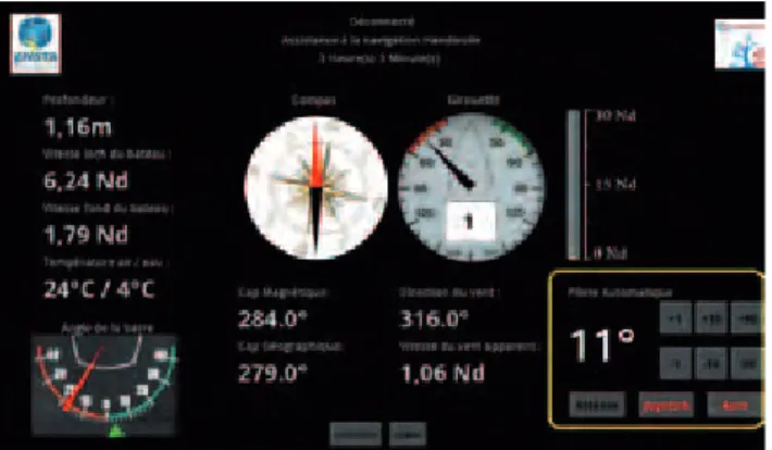
The HMI, programmed for Android by using the An-droid Software Develop-ment Kit tool for Eclipse, contains different areas (Figure 4): in addition to tex-tual information, some data, such as wind orientation and speed, compass and rud-der angle, is also displayed in graphic form to allow a better understanding of the environment. A last area
Figure 1: The system is based on a closed loop, where the user can be removed for autonomous behavior
Figure 3: System composed of an electric ram (in red), a joystick and a control keyboard (in blue) and the rudder (in green)
10
CAN Newsletter 2/2014
A
pp
lic
at
io
n
Figure 2: PSC of the Splashelec system in a waterproof case
Ethernet/CAN Gateway
EtherCAN CIARM9/RMD
CAN/Ethernet Gateway embedded Linux Kernel 3.5.0 ARM9 CPU / 454MHz 2GByte EMMC Flash 128 MByte RAM
Successfully applied in
• Machine automation
• Building automation
• Transportation systems
• Telecommunication systems
CAN/CANGateway CAN RepeaterIsolating
Physical Layer Analyser Optical
Fibre Transceiver
CAN Network Technology
+498441490260 www.emswuensche.com Sonnenhang 3 Tel. Fax. +49844181860 D85304 Ilmmünster NEW
acts as a virtual keyboard to switch between autopilot and joystick mode and the user can modify the course. The graphical layout of the HMI is realized in XML lan-guage and could easily be modified to fit the needs of specific users. This results in a system (joystick, tab-let display, extra keyboard, etc.), compatible with differ-ent disabilities, while still be-ing usable by sailors without any disabilities.
CAN protocol
The choice of the CAN protocol for our architec-ture arose from the need of a broadcast communica-tion mechanism, that had to be easy to use, able to work with multiple nodes, and which provides a reli-able communication proto-col to exchange information from sensors and actuators. Indeed CAN is able to de-tect errors with no less than three mechanisms: Cyclic Redundancy Check (CRC) to verify message integrity, Frame Check to verify that data is sent in the correct shape, and acknowledg-ments to guarantee recep-tion. Besides, adding nodes to an existing CAN network can be done easily, which meets our needs for a mod-ular architecture.
Adding nodes to the network is straightforward: adding a sensor with in-terfaces like for example NMEA183 (National Marine Electronics Association) or I2C (Inter Integrated Circuit) implies reading the data by the connecting nodes mi-crocontroller and to put the data in a CAN frame. Ardu-ino allows doing this in very few lines of code, using li-braries for CAN and a pleth-ora of choices for sensor interfaces.
Higher-layer protocol
At this point the need for a higher level CAN protocol to organize data in the CAN frames appears. Various higher-layer CAN protocols
already exist, such as J1939 used in NMEA2000, CAN Kingdom, or CANopen, but it appears that non of these fits our need for a simple CAN protocol. Too complex or not adapted for 8-bit mi-crocontrollers, CAN pro-tocols are not widespread and their code is not always open-source. We decided to develop our own protocol, based on our needs, called SimpleCAN, into an Ardui-no library containing the es-sential functions to support our architecture. The proto-col permits adding new fea-tures.
System architecture
Our architecture is based on Arduino compatibili-ty and uses a CAN inter-face called the CANinterfac-er, compatible to an Arduino with a CAN shield on top. This board [5] uses an AT-MEGA32U4 microcontroller as do the Arduino
Leonar-do and Micro. It is small in dimension (slightly smaller than 5 cm x 5 cm) and can be programmed via USB us-ing the Leonardo bootloader and the Arduino IDE. It can be powered through CAN by an on-board switching pow-er supply accepting from 7 V to 32 V. Most of the I/O pins are available for local con-nections.
In the system, a group of elements (actuators, sen-sors, HMI elements, etc.), wired to a CANinterfacer, becomes a CAN node (Fig-ure 5): each CANinterfac-er uses Arduino libraries to convert input from vari-ous sources, for example analog inputs, NMEA183 or I2C connected sensors,
into CAN messages. Putting a CANinterfacer between the new hardware and the bus to integrate it as stan-dard node increases the flexibility. In the same way, the PSC contains a CANin-terfacer and functions as a
native node in our bus sys-tem. This allows integrating servo-controlled actuators such as rams and winch-es with their associated sensors.
CAN bootloader
The CAN protocol imple-mentation opens the way to simplified programming of every node through the bus with only one connec-tion. To obtain that, an Ardu-ino bootloader that accepts CAN programming com-mands for our CANinterfac-er is needed. The Robotics Club of Aachen [4] has al-ready worked on the subject with very similar hardware and built its own CAN boot-loader that allows updat-ing firmware and local code from CAN messages. Small modifications have been made in order to suit con-nections of our CANinter-facer [5]. The programming operation is initiated by a Python script that initiates the communication process between the PC connected programming node and the node which needs to be re-configured. In practice, the programming node acts as an In-System Programming (ISP) interface: it receives the new program by USB or serial port and sends it encapsulated in CAN mes-sages to reprogram the specified node. The whole process is detailed in Weber’s The CANinterfacer [5].
Figure 4: The human machine interface displays sensor information and contains a virtual keyboard (in yellow) to replace the physical one
Figure 5: Examples of a CAN node: The joystick and the Programmable Servo Controller (PSC) in its first version; the next version will have a CANinterfacer integrated into the board
12
CAN Newsletter 2/2014
A
pp
lic
at
io
n
Demonstrator
The WRSC 2013 demon-strator [3] proves the flex-ibility of such an architec-ture. The choice of boat fell on a Miniji from ”Handivoile Brest”, based on a small scale of a historic America’s Cup hull. It is an inexpen-sive single-handed sailing boat, ordinarily steered by foot pedals or with a steer-ing wheel. It offers vivid sen-sations to the sailor seated in a comfortable position in a bucket seat.
Furthermore, instruc-tors working with disabled sailors demand an increase in autonomy and safety. To achieve this, a boat will be equipped with electric winches and a rudder sys-tem, all interconnected via CAN. Adding sensors to the bus, this boat will be able to perform automated tasks as a sailing robot. Indeed, to in-crease security, we can lim-it the heeling or restrict the navigational area. Instruc-tors will also be able to take control of the boat for safety reasons or even activate the autopilot.
A system based on a CAN architecture allows developers to connect new
sensors or actuators, and to reprogram the system using Arduino technology. Such a system assists the sailor during navigation and can automate complex tasks. It helps disabled people by easing the access to sailing activities and gives naviga-tional assistance to anyone. Based on the open-source approach, electronics and software can be modified according to specific re-quirements. Numerous pos-sibilities for development exist. The final aim is to ob-tain products with new fea-tures derived from robotic sailing, encouraging people to develop their own system modifications
References
[1] National Marine Electronics Association. NMEA2000(TM) standard, In: National Marine Electronics Association website http://www.nmea. org/content/nmea standards/nmea 2000 ed3 00.asp, 2012.
[2] N. Brocheton, K. Bruget, A. Wibaux, O. Reynet, B. Clement, and B. Weber. Systeme d’assistance a la navigation handivoile. In Proceedings of Handicap 2012: 7th congress on technical assistances for disabled people, Paris, France, 2012.
[3] K. Bruget, B. Clement, O. Reynet, and B. Weber. CAN bus interface board for sailing applications. In Proceedings of the 5th International Robotic Sailing Conference (Springer Eds.), Brest, France, 2013. [4] Fabian Greif. CAN Bootloader, In: Universal CAN
library. Roboterclub Aachen e.V. http://www.kreatives-chaos.com/artikel/ can-bootloader, 2010.
[5] B. Weber. The CANinterfacer, In: The Splashelec Wiki. http://wiki.splashelec.com/index.php/caninterfacer, Cited 13 May 2013.