Publisher’s version / Version de l'éditeur:
Proceedings of the 23rd International Conference on Port and Ocean Engineering under Arctic Conditions, June 14-18, 2015, Trondheim, Norway, 2015-06
READ THESE TERMS AND CONDITIONS CAREFULLY BEFORE USING THIS WEBSITE.
https://nrc-publications.canada.ca/eng/copyright
Vous avez des questions? Nous pouvons vous aider. Pour communiquer directement avec un auteur, consultez la première page de la revue dans laquelle son article a été publié afin de trouver ses coordonnées. Si vous n’arrivez pas à les repérer, communiquez avec nous à [email protected].
Questions? Contact the NRC Publications Archive team at
[email protected]. If you wish to email the authors directly, please see the first page of the publication for their contact information.
NRC Publications Archive
Archives des publications du CNRC
This publication could be one of several versions: author’s original, accepted manuscript or the publisher’s version. / La version de cette publication peut être l’une des suivantes : la version prépublication de l’auteur, la version acceptée du manuscrit ou la version de l’éditeur.
Access and use of this website and the material on it are subject to the Terms and Conditions set forth at
A large double-pendulum device to study load, pressure distribution
and structure damage during ice impact tests in the lab
Gagnon, Robert; Daley, Claude; Colbourne, Bruce
https://publications-cnrc.canada.ca/fra/droits
L’accès à ce site Web et l’utilisation de son contenu sont assujettis aux conditions présentées dans le site LISEZ CES CONDITIONS ATTENTIVEMENT AVANT D’UTILISER CE SITE WEB.
NRC Publications Record / Notice d'Archives des publications de CNRC: https://nrc-publications.canada.ca/eng/view/object/?id=8ab2ac1f-fd6f-49c1-9691-4f3003654309 https://publications-cnrc.canada.ca/fra/voir/objet/?id=8ab2ac1f-fd6f-49c1-9691-4f3003654309
A LARGE DOUBLE-PENDULUM DEVICE TO STUDY LOAD,
PRESSURE DISTRIBUTION AND STRUCTURE DAMAGE
DURING ICE IMPACT TESTS IN THE LAB
Robert Gagnon 1, Claude Daley 2, Bruce Colbourne 2 1Ocean, Coastal and River Engineering, National Research Council of Canada 2
Dept. of Engineering and Applied Sciences,Memorial University of Newfoundland
ABSTRACT
The design and functioning of a new impact device is described, where its eventual intended use is the study of damage associated with pressure distributions arising from ice impacts on ships. The large apparatus is a double-pendulum type device that is capable of achieving fairly high impact energies and velocities while remaining relatively ‘compact’ with respect to the confines of the laboratory space that is available. For example, at a drop angle of 35o from vertical for each pendulum the impact energy and relative velocity are ~ 31 kJ and 5.32 m/s respectively. Conical-shaped ice samples, one meter in diameter are held in a cylindrical ice holder that attaches to one arm of the double pendulum. For one type of test a unique instrumented panel (Impact Module), that records load and high spatial resolution pressure distribution during impacts, attaches to the opposite pendulum arm. For another test type the Impact Module is replaced by ship grillage (full-scale or reduced scale) so that ice impact tests can be performed that cause damage to the grillage. The pendulum arms are designed in a manner such that no rotation of the colliding masses occurs during tests. The effective masses of the colliding objects can be adjusted by adding or removing heavy metal plates. Similarly, the drop angles of the pendulum arms can be adjusted to achieve a range of impact velocities. These two adjustable features enable a variety of impact velocities and energies to be obtainable and allow for some degree of parameter-based study where either velocity or energy is fixed while the other is varied. To date a number of tests have been performed involving ice impacts on the Impact Module. Some representative sensor data that includes a few examples of the ice pressure distribution from one test are presented.
INTRODUCTION
As activities associated with resource development continue to increase in cold ocean environments such as the east coast of Canada and the Arctic, the need for updating and improving codes and rules for ships and structures to keep in step with the development is an ongoing issue. While large experiments of various types will have to be conducted, where the greatest emphasis would be on expensive full-scale field studies, there is still much (and less expensive) research that can be done in the controlled environment of the laboratory setting. In spite of the many laboratory and field studies that have been conducted in the past to investigate ice behaviour during impact and indentation there still remain significant, and at times contentious, topics such as the nature of hard zones and soft zones and how they evolve during ice-structure interaction. Add to this the issue of structure deformation and damage during the course of ice impact and indentation, and how that affects the pressure distribution pattern during the interaction, and one can easily appreciate the need for more study and, in
POAC’15
Trondheim, Norway
Proceedings of the 23rd International Conference on
Port and Ocean Engineering under Arctic Conditions June 14-18, 2015 Trondheim, Norway
some cases, novel approaches. Here we describe a new impact apparatus designed for laboratory studies of ice impacts on ship grillage that is capable of impact forces that will cause damage to suitably scaled grillage.
APPARATUS
A double-pendulum design was chosen for the apparatus to enable reasonably high impact loads while minimizing the space requirements since the Structures Lab at MUN is a congested environment with equipment for various types of ongoing experimental studies and student demonstration facilities. Also the design eliminated the need to have any kind of force reaction equipment that would ultimately transmit undesirable forces to the floor or walls of the room.
Figure 1 is a schematic of the apparatus that illustrates its essential features. Figure 2 is a photograph of the apparatus. An earlier design concept for the apparatus has been published before (Alam et al., 2012). Here we present the full apparatus as fabricated from the final design. Note that the figures show that both sides of the apparatus consist of masses that are supported by four parallel swing arms that attach to the masses through bearings. The tops of the swing arms attach to the apparatus frame via another set of bearings. This configuration enables the pendulum masses to swing freely and maintain a horizontal orientation while doing so. This eliminates undesirable rotation of the masses during impacts. The reader will note the toothed structure at the bottom of the test frame directly underneath the pendulum masses. This is part of the mechanism that prevents multiple hits of the pendulums that would arise from the masses bouncing apart after the initial impact and then re-colliding. Each pendulum has a brake device that consists of a metal plate, hinged on one end, that is normally held in the horizontal housing. The initial collision causes them to slide forward in
Figure 1. Schematic of the double-pendulum impact apparatus showing the ice holder pendulum (left) and Impact Module pendulum (right) in the raised position for a test. For future impact tests, where actual ship grillage will be used, the Impact Module will be removed and the grillage will be attached to the box structure that presently houses the Module. A second graphic of the brake device has been inserted to show how it functions. Note that some vertical structural members have been removed from the schematic to permit unobstructed views of the right and left pendulums.
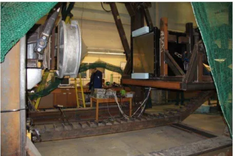
Figure 2. Photograph showing a partial view of the double-pendulum impact apparatus with the ice holder pendulum (left) and Impact Module pendulum (right) in the raised position for a test. The ‘toothed’ rail structure directly below the pendulums is the catch mechanism as shown in Figure 1. Protective netting is visible at the sides and in the background of the image. An overhead crane is used for lifting the pendulum masses to the desired elevation for a test.
the direction of the impact and out of the housing so that the free unhinged end falls down under the influence of gravity to be caught by the teeth of the catch mechanism (the toothed rail at the base of the apparatus) after rebounding.
Figure 1 shows the left pendulum of the apparatus with a conical-shaped ice specimen inside the ice holder that is fixed to the box structure at the bottom of the swing arms. The box structure serves as a mounting platform for the ice holder and has three load cells mounted directly behind the ice holder in an equilateral triangular formation. The box structure also serves as a carriage to which mass (in the form of steel or lead plates) may be added behind the ice holder. On the opposite side of the apparatus the figure shows the right pendulum which has a similar box structure at the ends of its swing arms and to which a device called the Impact Module, designed for measuring load and high spatial resolution pressure distributions during ice impacts, is inserted. As with the left pendulum, mass may be added to the box structure to increase impact energy. The intension of the double-pendulum apparatus, as shown in Alam et al. (2012), is ultimately to perform ice impacts against actual ship grillage. The Impact Module experiments are intended to augment the tests using ship grillage by providing detailed information on the ice pressure distribution during impacts. It is understood, of course, that this would likely be a crude approximation of the pressure distribution that would result if an ice impact on a ship occurred that caused the grillage to undergo plastic deformation. With this in mind some design consideration has been given to incorporating the pressure-sensing technology of the Impact Module into a thin sheet configuration that could be situated between the ice and the grillage during an impact and that could deform along with a grillage if the grillage sustained damage. However, such a thin sheet has not been fabricated yet. To date no grillage impact tests have been performed with the apparatus. Several impact experiments have been performed using the Impact Module and we will focus on results from one of those experiments here and in the accompanying paper (Sopper et al., 2015).
The following expression gives the impact velocity (V) for the mass on a pendulum for any given lift angle (Ɵ) from the vertical
V (1)
where g is the acceleration due to gravity and L is the length of the pendulum swing arm (2 m). Both pendulums are lifted away from each other to the same angle from vertical so that the relative impact velocity is double the value shown in Eq. 1. The associated impact energy (E) for an impact test where both sides of the pendulum have approximately the same mass (m) is
E = m V2 (2)
For the impact test that we will be describing here the pendulums were lifted to an angle of 35o from the vertical. The pendulum masses were approximately 4330 kg each. The associated relative impact velocity and impact energy were 5.32 m/s and ~ 31 kJ respectively. The ice holder has been described before (Alam et al., 2012). The method of fresh water ice sample preparation has been described by Reddy-Gudimetla et al. (2012). The final preparation stage before a test is conducted involves transporting the ice (frozen into the ice holder) from a freezer at –100C into the testing area using a forklift and then attaching the ice holder to the left pendulum. The test would ensue shortly afterwards. Some unavoidable heating of the ice surface would occur during the wait period.
Note that the Impact Module was originally designed to test a concept for a large impact panel to be installed on a vessel’s bow intended for bergy bit impact experiments. Due to the mass of the vessel it would not be expected that there would be significant decelerations of the vessel and impact panel during the bergy bit collisions. So one would only have to prevent shock vibration from the ice hitting the front of the Module and transmitting to the high-speed imaging camera that would cause blurring of images. This is easily done by having the camera rest of on soft rubber pads that enable the camera to ‘float’ while the pads absorb the shock vibrations. The present application, however, does entail fairly high decelerations of the Impact Module during tests and this causes the camera to move substantially on the rubber pads. This necessitates adjusting the images after each test to center, rotationally orient and scale them to compensate for this movement. This procedure is described in the accompanying paper (Sopper et al., 2015).
SAFETY CONSIDERATIONS
Due to the size of the apparatus frame and the massive components of its pendulums, considerable energy is stored in the equipment just prior to a test when both pendulums have been elevated to the desired height. To ensure the safe operation of the system a number of safe guards and procedures are in place. First, as shown in Figure 1, the high capacity release mechanisms can be seen for the two pendulums. Conceptually these are similar in design to quick release shackles used in marine applications that provide easy and safe release of heavy loads. Figure 3 shows details of the release mechanism. The design involves the use of a relatively small magnetic force to keep the free end of a hinged arm in place, where the pendulum mass is supported at the other end of the arm near the hinge. The pendulum is released by de-energizing the electromagnet. In addition to the electromagnet there is a manual lock mechanism that is always engaged until shortly before a test.
Before arming the system by raising and locking the pendulum arms in place for a test all secondary staff and spectators are required to move away from the immediate vicinity of the device. Then, after the manual locks on the release mechanisms have been opened the remaining staff move away from the apparatus. Additionally, the frame of the apparatus is fully encompassed by a polypropylene net to prevent ice chunks from flying away from the impact zone that might cause damage to computer and camera equipment near the apparatus or possibly harm the staff that are located at a farther distance.
IMPACT MODULE DESCRIPTION
The Impact Module and its unique pressure-sensing technology have been described before and we include the description here. The central
component of the Impact Module is a thick transparent block of acrylic measuring 1 m x 1m x 0.46 m (Figure 4). The block rests on four flat-jack type load cells. These load cells are metallic envelopes filled with hydraulic fluid. Load applied to the surface of the cell translates into pressure in the fluid, which is monitored by a pressure gauge. The thickness of the acrylic block gives it the flexural strength to withstand high loads while supported at its four corners. The block is held firmly against the load cells by two bolts that pass part-way through opposing corners of the block and that are secured with nuts and strong springs. Also, around the top edge of the block there is a securing plate that bolts to the steel side plating of the Impact Module with nuts and springs. This protects the edges of the block where a thin stainless steel sheet, that covers the new pressure-sensing technology, is screwed to the block while enabling the load from an ice impact to transfer to the flat load cells.
The top surface of the block is covered by new pressure-sensing technology. This new technology consists of many strips of acrylic, 13 mm wide and 4 mm in thickness and ~ 1 m in length, mounted side-by-side on the block’s surface. Each strip has a gentle curvature (0.23 m Figure 4. Sectional view of the Impact Module.
(From Gagnon (2008)).
Figure 3. Schematic of the pendulum release mechanism.
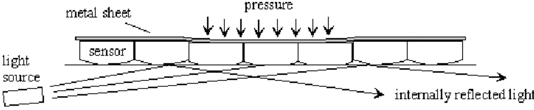
radius) across its width on the face that touches the large acrylic block (Figure 5). Pressure applied to the opposite side of the strips causes them to flatten against the block’s surface. The degree of flat contact, i.e. the width of the contact, is a direct measure of the pressure applied and can be calibrated. This type of sensor is very robust and has been used successfully in a number of ice crushing studies (Gagnon and Bugden, 2007; Gagnon and Bugden, 2008; Gagnon and Daley, 2005), in single and multiple strip configurations. Its range of sensitivity is about 0-60 MPa. The pressure sensor strips are covered by a thin sheet of stainless steel that is the contacting surface with the ice during impacts. The unit sensing area for this technology is about 3 cm2, hence the top surface of the block is effectively covered by about 2500 pressure-sensing units. The data acquisition system for the pressure-sensing strips is a fast high-resolution imaging camera (AOS S-PRITM ), operating at 500 images/s with resolution of 1280 x 1024 pixels, located at the bottom of the block as shown in Figure 4. When not pressed against the acrylic block the strips make very little contact, and when pressure is applied more contact occurs due to elastic flattening of the strips’ curved surfaces (Figure 5). To enhance the visibility of the flattened areas of the strips a thin sheet of opaque white plastic film (MonokoteTM) is loosely situated between the acrylic strips and the large acrylic block. This thin sheet provides a bright white representation of the flattened areas of the acrylic strips where they are pressed against the acrylic block during loading. The only light source inside the acrylic block is from a large number of horizontally oriented LED’s located around the block perimeter near the top. Light from these LED’s normally internally reflects off the top inner block surface. When an acrylic strip is flattened against the film-covered block the internal reflection is frustrated, and the light passes through the block’s surface to illuminate the white plastic film where the strip makes contact. Hence the portion of strip contact, appearing as white, becomes visible to the camera.
Figure 5. Schematic showing how the new pressure-sensing technology functions. Two of the light rays from the source at the left internally reflect off the block’s internal surface where there is no contact with the strips. The center ray illumines the ‘white’ acrylic strip since the internal reflection is frustrated where the strip is elastically flattened against the block due to the pressure. The curvature of the strips is exaggerated for illustrative purposes. (From Gagnon (2008)). Note: the strips are clear acrylic, however the thin opaque white plastic film (not shown) between the block and the strips essentially behaves as a thin coat of resilient white paint on the strips’ bottom surfaces.
In addition to the pressure-sensing strips the top surface of the block has an array of 9 strain-gauged pressure-sensing plugs recessed in it. These are small cylinders of acrylic (2.5 cm diameter) that are located and secured in flat-bottomed holes (with slightly larger diameter) machined in the surface to the exact depth corresponding to the height of the plugs. The end of each cylinder is glued to the acrylic at the bottom of the hole with Loctite 5900TM glue. Each plug has two strain gauges attached at opposite sides with sensitivity along the axis of the plug. Load applied to the top of a plug causes it to contract in length and this registers on the strain gauges. The plugs are essentially pressure transducers that have the same mechanical properties as the block itself. The sensors are useful both for corroborating the output from the pressure-sensing strips and as backup sensors in the event there is a problem with the strip sensors.
REPRESENTATIVE TEST DATA
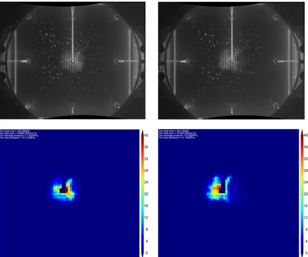
Figure 6 (Top) shows two partially processed images acquired from inside the Impact Module during the impact test. The process for converting the raw images to pressure distribution images is described in the accompanying paper (Sopper et al., 2015). As mentioned above, the test was conducted with the pendulum arms at an angle of 35o from vertical. This implies that the relative impact velocity and impact energy were 5.32 m/s and ~ 31 kJ respectively. The high-speed imaging camera in the Impact Module was running at 500 images/s during this test. Figure 6 (Bottom) shows the fully processed images. The left and right images are separated in time by 0.002 s, and they show the pressure distribution just prior to and after an ice spall had broken away from the right side of the contact area. The images show that the ice contact region typically consists of relatively intact ice, called hard zones, of varying shapes that are surrounded by soft zone regions that consist of crushed ice that is the remnants of shattered and pulverized spalls. The physical mechanisms governing the crushing behaviour of the ice and the shape and size evolution of the ice contact have been described before (Gagnon, 1999). We have included these two images to demonstrate the device’s capability to capture rapidly changing pressure patterns associated with aspects of ice crushing.
The left image in Figure 7 shows the pressure pattern that had developed at the point in the test when ice penetration had stopped, at ~ 0.04 s after first contact, and it illustrates the dramatic changes in shape and size of the contact area that occurred during the impact. The right image in Figure 7 is a photograph of the impacted ice sample shortly after the ice holder had been removed from the apparatus. One can clearly discern the shape of the high-pressure ice contact region, as depicted in the left image, as the darker area of the contact zone in the photograph. Recall that high-pressure zones consist of relatively intact ice.
The full set of processed images for this test are described in the accompanying paper (Sopper et al., 2015). Note that the pressure values indicated in the images are somewhat higher than the actual pressures because the acrylic pressure strips that are the key element of the technology were calibrated in the lab at a temperature of 0oC whereas the present tests were conducted at room temperature. Hence, the elastic response of the acrylic is greater in the latter case. The original calibration was at 0oC because the technology is intended for use in a field study of ship collisions with bergy bits where the water temperature will be near 0oC. The pressures measured by the pressure strips could, in principle, be corrected for the temperature difference by comparing loads measured by the load cells with the loads obtained by integrating pressure pattern images when the hard zone contact does not cover the pressure plug. Of course the best strategy to avoid this discrepancy in the long term is to perform a calibration of the pressure strip technology at room temperature. Another strategy would be to cool the sensing-surface portion of the Impact Module to 0oC prior to tests.
In the accompanying paper (Sopper et al., 2015) the full set of processed images from this test are presented along with the load data from the load cells of the Impact Module, the loads obtained by integrating the pressure strip patterns and the pressure data from the central pressure plug. In the discussion it will be seen that while the absolute values of the pressure values for the pressure plug correspond to only a portion of the ice contact area, we may still correlate events in the pressure record with events that are evident in the pressure strip patterns, such as abrupt spalling events.
Figure 6. (Top) Two consecutive images taken before and after a spalling event by the high-speed imaging camera viewing through the acrylic block inside the Impact Module during an ice impact test. The images have been processed to remove distortions associated with the fisheye camera lens and movement of the camera during the test. The camera was operating at a rate of 500 images/s. The cloud of small air bubbles visible in the images, that is a remnant of the acrylic block casting process, does not affect test results. (Bottom) Pressure distributions determined from full processing of the two images above. Note that the actual pressures are somewhat lower than that shown in the figures due to the test having been conducted at room temperature whereas the pressure-sensing technology was calibrated at 0oC. The width of a blue box is ~ 0.87 m. The unit on the colour scale is MPa.
CONCLUSIONS
A double-pendulum impact apparatus has been described for studies of ice impacts on ship grillage in the lab. So far the device has been used for tests of ice impacts against an Impact Module that measures pressure distribution and load. The tests to date have shown that the double-pendulum apparatus functions as intended and can be operated in a safe manner in the laboratory setting. Test data from the Impact Module have demonstrated the system’s capability to provide a map of the ice pressure distribution with high spatial and temporal resolution.
ACKNOWLEDGEMENTS
The authors would like to acknowledge the financial support of Atlantic Canada Opportunities Agency, Research and Development Corporation, American Bureau of Shipping, BMT Fleet Technology, Husky Energy, Rolls-Royce Marine, Samsung Heavy Industries. Also, we are grateful for the invaluable participation of the National Research Council Canada in the form of providing expertise for all aspects of the apparatus development and experiments, and for the use of a unique scientific instrument.
REFERENCES
Alam, M.S, Daley, C., Colbourne, B., Hermanski, G., Gagnon, B., Bruneau, S., Clarke, G., Quinton, B., 2012. Double Pendulum Dynamic Impact Test Set-up for Ice-Grillage Collision. Proceedings of ICETECH 2012, Paper No. ICETECH12-134-RF.
Gagnon, R.E., 1999. Consistent Observations of Ice Crushing in Laboratory Tests and Field Experiments Covering Three Orders of Magnitude in Scale. Proceedings of the 15th International Conference on Port and Ocean Engineering under Arctic Conditions, 1999, POAC-99, Helsinki, Finland, Vol. 2, 858-869.
Gagnon, R.E., 2008. A New Impact Panel to Study Bergy Bit / Ship Collisions. Proceedings Figure 7. (Left) The pressure distribution from an image captured during the impact at the point when ice penetration had stopped. The size and shape of the contact region is dramatically different than earlier in the test as shown in Figure 6. (Right) A photograph of the impacted ice sample shortly after the ice holder had been removed from the apparatus. The shape of the high-pressure ice contact region, as depicted in the left image, is clearly visible as the darker area of the contact zone.
of 19th IAHR International Symposium on Ice 2008, Vancouver, British Columbia, Canada, Vol. 2, 783-790.
Gagnon, R.E. and Bugden, A., 2007. Ice Crushing Tests Using a Modified Novel Apparatus. Proceedings of POAC-07, 235-244.
Gagnon, R.E. and Bugden, A., 2008. 2-Dimensional Edge Crushing Tests on Thick Sections of Ice Confined at the Section Faces. Proceedings of 19th IAHR International Symposium on Ice 2008, Vancouver, British Columbia, Canada, Vol. 2, 763-771.
Gagnon, R.E. and Daley, C., 2005. Dual-axis video observations of ice crushing utilizing high-speed video for one perspective. Proceedings of POAC 2005, Potsdam, New York, Vol. 1, 271-282.
Reddy-Gudimetla, P.S., Colbourne, B., Daley, C., Bruneau, S. and Gagnon, R., 2012. Strength and Pressure Profiles from Conical Ice Crushing Experiments. Proceedings of ICETECH 2012, Paper No. ICETECH12-132-RF.
Sopper, R., Gagnon, R., Daley, C., Colbourne, B., 2015. Measurements of spatial and temporal variations in ice impact pressures. POAC-2015, Trondheim, Norway.