OATAO is an open access repository that collects the work of Toulouse
researchers and makes it freely available over the web where possible
Any correspondence concerning this service should be sent
to the repository administrator:
[email protected]
This is an author’s version published in: http://oatao.univ-toulouse.fr/24571
To cite this version:
Benoist, Vincent
and Baili, Maher
and Arnaud, Lionel
Design for additive manufacturing including machining constraints:
A case study of topology optimization including machining forces.
(2019) In: First International Conference on Innovative Materials,
Manufacturing, and Advanced Technologies : IMMAT'2019, 17
October 2019 - 19 October 2019 (Monastir, Tunisia).
Design for Additive Manufacturing including machining constraints: A
case study of topology optimization including machining forces.
V. BENOIST 1
!, M. BAILI 2
, L. ARNAUD 3
a
Laboratoire Génie de Production, École Nationale d’Ingénieurs de Tarbes, Université de Toulouse,
INP-ENIT, Tarbes Cedex, France.
b
Mécapole Cousso, Avenue cassou de Herre BP 25, 32110 Nogaro
Résumé – La fabrication additive métallique est un champ de recherches et d’innovation majeur. Dans l’industrie aérospatiale beaucoup d’efforts sont fait pour modéliser et optimiser des conceptions. Dans ce contexte, malgré de nombreux efforts, la fabrication additive métallique (spécialement la SLM) produit encore des pièces considérées comme brute qui ont des surfaces nécessitant des finitions d’usinage dans le but d’obtenir la qualité géométrique demandée. L’étape de finitions par usinage n’est jamais prise en compte dans le processus de conception, spécialement avec l’utilisation de l’optimisation topologique. Dans cet article, une méthode de conception pour la fabrication additive (DFAM) est proposée dans le but d’optimiser l’étape de conception en incluant l’optimisation topologique, l’usinage, les contraintes mécaniques et géométriques. Il est montré que sur une pièce aéronautique les efforts d’usinage sont en général les efforts les plus importants que la pièce subit. En utilisant deux logiciels d’optimisation topologique (Inspire / Abaqus Tosca) il est montré qu’il est possible de prendre en compte la majorité des contraintes d’usinages pour modifier légèrement la conception initiale et ainsi simplifier les opérations d’usinage ultérieures et réduire ainsi les échecs éventuels durant l’usinage.
Mots clés : Fabrication additive / conception / modélisation / optimisation topologique/ aéronautique
Abstract – Metal additive manufacturing is a major field of study and innovation. In aerospace industry a lot of effort is made to modelise and optimize the designs. In this context, despite all efforts, metal additive manufacturing (especially SLM) still produce part generally considered as raw parts which still have some surfaces to be machined in order to obtain the required geometrical quality. Despite sometimes, great complexity and cost related to the finishing process, the machining stage is never taken into account in the design process, especially using the topological optimization approach. In this paper, a new Design for Additive Manufacturing (DFAM) method is proposed in order to optimize the design stage including topological optimization, machining, geometrical and mechanical constraints. It is shown on a typical aeronautical part that cutting forces may be the greatest forces during all the part life-time. Using 2 different topological optimization software (Inspire / Abaqus Tosca) it is shown that it is possible to consider most of the machining constrains to only slightly modify the initial design and thus simplify the machining stage and reduce possible failure during machining. Finally, machining test, geometrical accuracy control and pressure test validate the approach.
1 Introduction
Metal Additive Manufacturing (AM) processes, such as SLM (Selective Laser Melting), is a breakthrough technology for prototyping and even mass production, but one of the main drawbacks of this technology is a relatively poor dimensional accuracy and poor roughness quality, compared to machining. The general dimensional accuracy of SLM is about a tenth of a millimetre. Due to the lack of precision of the SLM machines most of the part need to be finished using a post process as machining. On the other side of the chain process, designs tools such as topology optimization can be fully applied to additive manufacturing but manufacturing forces (cutting forces) and fixture constrains (forces and fixture surface) are never explicitly considered during the initial topology design optimization. In this paper, several software using SIMP [1], [10] and RAMP [8] topological optimization methods have been compared, Then the Design for Additive Manufacturing methods (DFAM) will be quickly presented to show how our approach extend them. Then our approach will be explained and illustrated with an industrial aeronautic part and experimental validation tests (pressure tests and machining tests). Finally, we will conclude and discuss on the necessary evolution of design for additive manufacturing including post-processing and especially machining.
DFAM definition has been given by [7], [4] and [5] Parts obtained by additive manufacturing allows new opportunities for product performance and customization improvement due to its low manufacturing constraints. This increase in product performance are enabled also due to several parameters as:
Shape complexity: Due to the layer way of manufacturing, this shape freedom allows the designer to use numerical tools as topology optimization in order to obtain generative deign. Material complexity: Some of additive manufacturing processes allows to process material one layer, or even one point at a time which enable to design material property gradient from one or multiple materials.
In this paper, the focus will be on SLM due to our test part treated further. SLM can be attended to have
a specific AM process due to its important manufacturing constraints which is supporting. For few years, several works about DFAM have been investigated through literature. Some common designs parameters are found in [9], [6] and [7]. Indeed, some required data are needed in the DFAM process as:
The functional specifications are given by the customer specifications but also by observing the surrounding of the treated part. There are composed of the functional surfaces which are surfaces mandatory for the proper performance of the part as the link with other parts or transmitting mechanical or thermal loads. The functional surfaces are detailed by a set of geometrical and metrological specifications (dimensions, positions). The part is designed to resist some mechanical requirements (stress, vibrations, …) which depend on the material chosen and the customer specifications. And finally, some empty volumes have to be considered. These volumes contain no material in order to model assembly constraints of the part in the system. And also, these volumes can be used as clearing volume to prevent he part from collating other parts in the system or to allow fluid circulation.
The manufacturing characteristics to be considered in the design process, even with the wide freedom in design allowed by SLM, are the maximal and minimal dimensions of the printing volume, the accuracy in terms of dimensions and some physicals phenomena technology specific related which explain the final properties of the part. In the case of the SLM process the fact that supports are needed, to ensure the well printed part, is mandatory. Indeed, the designer has to think about the topology of the part in order to minimize the supports.
The last point which is needed in the DFAM process is to integrate the finishing process characteristics. For example, SLM process allows to achieve an accuracy of a tenth of millimetre which is, most of the time, insufficient in terms of customer specifications. So, a post printing finishing process is needed as machining. Some parameters have to be considered to ensure that the finishing process will be possible, as over-thickness and required accessibility.
The first step consists in the dimensional and geometrical specifications analysis in order to delimitate the design problem. With this analysis, the
first parameter to determine is the functional surfaces.
The second step consists in finding the functional volumes which are a defined thickness times the functional surfaces. But the thickness has to be defined using several parameters. As, the dimensional accuracy of the additive manufacturing and also, the over-thickness needed by the subtractive post processing (machining).
The last step consists in creating the link between the assembly requirements and the capability of the additive manufacturing process. The concept of manufacturing direction has to be considered. It will also influence the building time and the mechanical properties of the part.
2 Modeling
Based on the DFAM methods found in the literature and presented in the previous section, a new DFAM method has been developed with the particularity the machining constraints are in the centre of the design process.
Before presenting the design process, the parts used to illustrate our method need to be described. The choice of the part has been based on several parameters which are presented in [2]
The aeronautical part chosen is a 2 ways hydraulic bloc made in Ti6Al4V which was previously machining.
By analysis of the customer specifications, the main constraint of this part has been determined as the pressure of 31 MPa induced by the oil circulation. Knowing that mechanical specification, it allows the designer to calculate, using FEM model, the minimum thickness to assure the well mechanical tolerances of the part
Due to the shape freedom given by the additive manufacturing process it is possible to change the ducts topology in order to improve their performances in terms of pressure-drop reductions. This upgrade was presented in [2]
The next step of the DFAM method is to define the functional volumes. Using thickness equation in [6] we were able to calculate the over thickness needed to the machining post process.
Now that the mandatory volumes are defined, the next step of this new DFAM method, is to create the
stress set up that the product will encounter during its life time. But when using topology optimization algorithms each and every constraint it will encounter, from the manufacturing process to the maintenance of it, have to be forecasted.
As the initial part is machined, in order to reduce the cost, we have considered as a short-term solution to use the machining program already created for the initial forged part. But the main difference between forged and printed part is, in the case of the printed one, the only machining steps needed are to ensure the respect of the geometrical tolerances which are not achievable by the SLM technology precision. However, the cutting forces are not the only major forces which are mandatory to implement. Indeed, we considered, the so-called manipulation forces [2]. These manipulation forces represent the forces the part will encounter outside its functional constraints, as the pressure or the eigen frequencies, and also outside the cutting forces. They are the forces the part can encounter during mounting/unmounting and maintenance phases. In [2] we found that some of manipulation constraints were trifling compared to cutting forces.
In [3] we developed a cutting forces finite element numerical model to determine the machining constraint, in Ti6Al4V, the part will encounter during machining phases. Using Abaqus software, we created a 2D model of a cuboid sample representing the part and an infinite rigid shape representing the tool.
The results of the modeling show us the primary shear stress zone where the milling constraint is the most important. The value for the machining constraint is estimated about 2000 MPa. In this paper, the precise modeling of the cutting physic is not shown.
Now, the functional surfaces have been identified, the mandatory volume calculated, the main functional constraint, the manipulation constraints and the machining constraints determined. The next step in our DFAM method is considering all these variables in the topology optimization model. To resolve the topology optimization problem, two software were used: Abaqus Tosca® and Inspire®. Using both of those software lets us investigate which of each software is the most useful based on the topology problem complexity. Indeed, each topology optimization problem has is own complexity depending on the surrounding
environment of the part, and the constraints it will be subjected. If the part will encounter only basic static mechanical, Inspire® is a perfect software to use because of its really easy user-friendly approach and its quick calculation. At the contrary, Abaqus Tosca® can treat complex mechanical problems or even multiphysics problems. But complexity usually involves none user-friendly interface and modeling creation. We implemented the hydraulic bloc in both software with the goal to replicate the same modeling. Replicate it will allow us to compare the algorithms behind the results given by them. And with this comparison the designer would manage the topology optimization problem in terms of time and cost reduction.
In Inspire®, the establishment of the optimization model is done quite quickly due to the friendly user interface. The different variable to enter are the following:
- Firstly, the material needs to be chosen, in Inspire® the designer has at his disposal a material library which includes some material parameters as the Young modulus (116 GPa), the Poisson’s ratio (0.31), the density (4.43 g/mm³), the Yield stress (1100 MPa) and the coefficient of thermal Expansion (17.3E-6/K). The material values are those for a Ti6Al4V SLM manufactured.
- When the material is chosen, the part has to be divided in two different volumes, the mandatory volume which is, as explained before, the non-optimized volume mandatory to preserve the mechanical properties of the part. And the optimized volumes, called design volume in Inspire®, which represent the volumes where the topology optimization volumes will interfere.
- The next step is to manage all the constraints applied to the part. Inspire® is a software coded to allow a maximum of designers to use it, which implied to be straightforward and so the constraint implementation only allow to choose between point forces, pressure and moment. This poor choice in force representation compel us to apply a point force of 2000 N, which represent the cutting force. But the force is applied at the extremity of the coupling to represent where the cutting force is the most
constrained for the part. The others constraints (pressure, boundary conditions and moments) are easily implemented using the “Loads” tool in Inspire®. - Finally, the optimization calculation has to
be created and calibrated. Inspire® provides two different solution to resolve a topology optimization problem. The designer can “maximize the stiffness” which is the minimization of the strain energy. And the constraint linked to the objective function, is the percentage of total design space volume and it is use to specify the amount of material to keep. In the other hand, the objective function is the minimization of the mass with a stress constraint, which is represented by the respect of a minimum safety factor. For our modeling we choose to maximize the stiffness with a volume constraint of 25 %. And we added a frequency constraint in order to respect the aeronautical standard which tell that the first eigenvalue should be superior to 2500 Hz.
In the case of Abaqus Tosca® the implementation of the data is similar to Inspire®. We keep the same cutting force representation as in Inspire even if Abaqus® allows us to represent in a more real way the cutting force. The point force representation is kept in order to have the most similar modeling between both software. The only difference between both modeling is that in Inspire mesh cannot be controlled. In Inspire® there is no tool to choose the shape and the size of a mesh. The only parameter which constraint the mesh is named “thickness constraints” that enable to control the of the beam and wall minimum and maximum thickness. This constraint indirectly influences the mesh size but it not allows the designer to choose the mesh. In the other hand, in Abaqus® the mesh can be chosen and optimize in order to improve the calculation time. In both modeling the mesh is composed of tetraedric elements.
The differences between Abaqus® and Inspire® are:
- As shown previously, the mesh cannot be truly modified in Inspire so the mesh optimization in Inspire® doesn’t exist while in Abaqus® the mesh can be precisely optimized and the calculation times reduced. So, it is a great tool when the
modeling require a specific mesh due to small details for example. To conclude on this specific point, Abaqus® is the most powerful software in terms of mesh optimization and should be used each time the modeling needed to be optimized in order to reduce the calculation time. In the other hand Inspire, can be a quick tool in case of easy modeling, in terms of part shape.
- As said previously, Inspire® is an user friendly interface software, which induces a poor choice in representation of constraints. And in Abaqus ® the constraint representation can be very precise and real. So, this difference between constraints representations, allows the designer to choose the software in function of the stress representations and the complexity of the different loads and boundaries conditions. - Finally, the most important difference
between this two software is the variables possible to use as objective function or constraints in the topology optimization calculation. Indeed, in Inspire® the topology optimization calculations are based on stiffness maximization or mass minimization, with a stress constraint or mass constraint and an eigenfrequency constraint. But, in Abaqus Tosca®, there are more option to choose in order to adapt the topology optimization calculation to solve the problem. These options are found in the module “design response” and a design response is a single scalar value which can be referred to from objective functions or constraints. When the design response is chosen, the designer needs to choose the region where it will be applied. It is possible to applied it on the whole model, on a body (elements) of the model which is a selected region or it is applied on points (nodes). Finally, for each design responses an operator must be chosen. For variables, such as volume, weight, moments of inertia and gravity only the sum of values across the design aera is selected. For variable such as stress, contact stress and strain the only operator selected is maximum value. And for the other variable the choice could be those two operators but also the last one which allows to select the minimum value across the design aera.
All these differences allow, in this DFAM method, to select which software is the most appropriate in function of the modeling complexity. Each software has its pros and cons to take into account in order to optimize the process of modeling and so reduce the industrialization time and so the cost of it.
3 Results
In this part, the results of the modeling on both software will be presented. Afterward, we will discuss about results between this two software. This discussion will allow to know the difference in topology optimization algorithms to improve the designer knowledges and to help him further in his process.
We will begin to present the results from Inspire®. The optimization calculation that we have done is a stiffness maximization with a constraint of the percentage of total design space volume of 25 % and a frequency constraint which fix the first eigenvalue further 2500 Hz. The last parameters to add at the calculation is the independency of each load case to prevent them to cancel each other.
The non-optimized hydraulic bloc, in T6Al4V, has a mass of 210 grams. After the topology optimization calculation, the mass of the part becomes 91 grams. So, this calculation allows a mass reduction of 57%. Using only these results, the mass constraint is not respected. The non-respect condition is caused by the mandatory volumes. In Inspire® the mass constraint takes into account only the design volume. If we calculate the difference of mass between the design volume before and after the optimization, we obtained a difference of 72%. Which is closer than the 75 % mass reduction target. The results are shown in figure 1.
Figure 1: Optimized part obtained with Inspire
Now that the results from Inspire have been presented, we will show those obtained by Abaqus®. So, the calculation with Abaqus® has the same
optimization criteria and constraints than in Inspire®. After the topology optimization the mass of the part is of 99 grams. So, the mass reduction is about of 53%. The results are shown in figure 3.
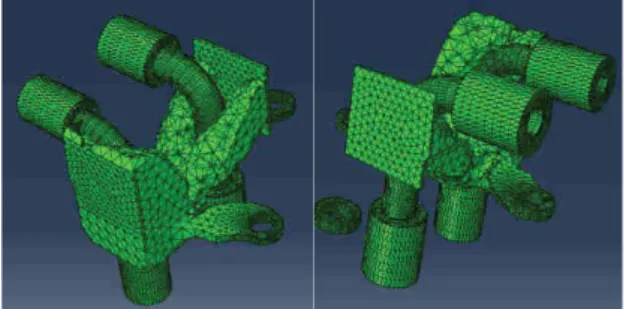
Figure 2: Optimized part obtained with Tosca
Now the both results have been presented, we will describe the differences between both software. The main difference between both results is the shape of the optimized part. Indeed, the fact we used two different algorithms to resolve the same topology optimization problem allows to major changes; In the Abaqus® results, figure 3, one fixation is not linked to the rest of the part. It is due to the lack of stress in this part of the design volume and also that the gravity is not taken into account so the fixation it is considered as fixed.
These differences in the results obliged us to consider that the modeling cannot be done in the same way from software to another. The goal of this DFAM method is too take into account all the constraints of an aeronautical part design, which include to give some advices to the designer in his process in terms of time optimization.
4 Conclusion
In this paper the goal is to present a new DFAM method to improve the design step of aeronautical part, taking in consideration the need of post processing as machining. This new method is principally based on topology optimization with the consideration of cutting forces in the modelling. And finally, the difference between two topology optimization software which are Inspire® and Tosca® are detailed. These researches have been based on a titanium aeronautical hydraulic bloc which is normally machined. This part presents some great improvement which were shown in previous papers. In this paper a topology optimization of the bloc using both software was conducted. It allows to know the difference between the algorithms and in order to the designer in his design process, to choose which software is the most efficient depends on the specifications. It is shown that the modelling should be different from one software to another, even with
the same specifications in order to obtain a viable result. This DFAM method is not yet completed, some other researches have to be done. Firstly, the designed part needs to be printed and machined to legitimate the method. And finally, this method needs to be extended to other parts.
5 References
[1] Bendsøe M.P Optimal shape design as a material distribution problem. Struct. Optim. 1, 193–202 1989
[2] Benoist V, Arnaud L, Baili M, Topological optimization design for additive manufacturing taking into account flexion and vibrations during machining post processing, HSM 2017
[3] Benoist V, Arnaud L, Baili Improved Design methodology for Additive Manufacturing including machining load cases: Application to an aeronautical workpiece. MUGV 2018
[4] Gibson I, Rosen D.W, Stucker B. Design for additive manufacturing, Additive Manufacturing technologies, 283-316, 2010
[5] Kumke M, Watschke H, Vietor T, A new methodological framework for design for additive manufacturing, Virtual and physical prototyping, volume 11, 3-19, 2010
[6]
Ponche R A new global approach to design for additive manufacturing: A method to obtain a design that meets specifications while optimizing a given additive manufacturing process is presented in this paper, Virtual and Physical Prototyping, Vol. 7, No. 93 105 2012[7] Rosen WD Design for additive manufacturing: A method to explore unexplored of the design space, 18th annual solid freeform fabrication symposium 2007
[8] Stolpe M, Svanberg K, An alternative interpolation scheme for minimum compliance topology optimization Struct Multidisc optim 22, 116-124, 2010
[9] Vayre B, Vignat F, Villeneuve F, Designing for additive manufacturing, Procedia CIRP, Volume 3, 632-637, 2012
[10] Zhou M, Rozvany G.I.N, The COC algorithm, Part II: Topological geometrical and generalized shape optimization, Computer methods in applied mechanics and engineering, 89, 309-336, 1991