Faculté de génie
Département de génie civil
Effet des ajouts minéraux sur le béton à haute performance:
formation de C-S-H et propriétés physico-mécaniques
Effect of mineral admixtures on high-performance concrete: C-S-H formation
and physical-mechanical properties
Thèse de doctorat
Spécialité: génie civil
Jorge Maurilio Rivera-Torres
Jury: Arezki TAGNIT-HAMOU (directeur)
Alejandro DURÁN-HERRERA (directeur)
Ammar Yahia (évaluateur)
Richard Gagné (évaluateur)
José Manuel Mendoza Rangel (évaluateur)
UNIVERSIDAD AUTÓNOMA DE NUEVO LEÓN
FACULTAD DE INGENIERÍA CIVIL
“EFECTO DE LOS ADITIVOS MINERALES EN CONCRETOS DE ALTO COMPORTAMIENTO: FORMACIÓN DE C-S-H Y PROPIEDADES
FÍSICO-MECÁNICAS”
POR
JORGE MAURILIO RIVERA TORRES
COMO REQUISITO PARCIAL PARA OBTENER EL GRADO DE DOCTOR EN INGENIERÍA DE MATERIALES DE CONSTRUCCIÓN
Y ESTRUCTURAS
i
Abstract
In order to improve the environmental impact of concrete, there is a global trend to replace Portland cement by mineral admixtures. In addition to the reduction in the environmental impact of the material, the incorporation of supplementary cementitious materials in concrete will densify the cementitious matrix and consequently improve its impermeability, a property associated with the durability and the service life of concrete. However, in most cases, the performance of a cementitious material is typically evaluated through the impact on the mechanical properties and the cost, leaving aside the durability and the effects at the microstructural level.
This work intends to study the effect of supplementary cementitious materials on formation of C-S-H and the development of the concrete microstructure. The effect of this development on mechanical properties and durability is evaluated. In this investigation, concretes with water/binder ratio of 0,45 and 0,35, where Portland cement is replaced by natural pozzolan or fly ash in dosage of 20% and 60% by mass of each material where used.
The experimental results indicate that the incorporation of 60% natural pozzolan leads to the production of concretes extremely resistant to the chloride ingress without a significant decrease in the compressive strength and modulus of elasticity (11% and 10% respectively at 90 days). The paste analysis by nanoindentation in combination with the qualitative Energy-Dispersive Spectroscopy (NI-EDS) reveals that the physical and mechanical properties of concrete with natural pozzolans are originated from an optimal combination of aluminum-containing hydrated products, a predominant phase of C-(A)-S-H and a well distributed small hard anhydrous inclusions. While the compressive strength and the modulus of elasticity in plain Portland cement concretes depend mainly on the formation of C-S-H.
Keywords: Durability, natural pozzolan, chloride ingress, mechanical properties, nanoindentation, anhydrous inclusions, C-S-H, C-(A)-S-H.
ii
Résumé
Afin d´améliorer l'impact environnemental du béton, il existe une tendance mondiale à remplacer le ciment Portland par des adjuvants minéraux, parce que en plus de réduir l'impact environnemental du matériau, l'incorporation de matériaux cimentaires supplémentaires dans le béton permet de densifier la matrice cimentaire et, par conséquent, améliorer son imperméabilité, propriété associée à la durabilité et à la vie utile du béton. Toutefois, dans la plupart des cas, la performance d'un matériau cimentaire est généralement évaluée par l´impact sur les propriétés mécaniques et le coût, en laissant de côté la durabilité et les effets au niveau microstructural.
Ce travail vise à étudier l'effet de ses propriétés mécaniques et de leur durabilité des matériaux cimentaires supplémentaire sur la formation des C-S-H et le développement de la microstructure du béton. Cet effet sur les propriétés mécaniques et la durabilité ont été évalués. Dans cette recherche, des bétons (avec un rapport eau/ciment de 0,45 et 0,35) ou 20% et 60% du ciment portland a été remplacé par des pouzzolanes naturelles ou des cendres volantes, ont été utilisés. Les résultats obtenus expérimentalement indiquent que l'incorporation de la pouzzolane naturelle avec un dosage de 60% conduit à la production de bétons extrêmement résistants à la pénétration des chlorures sans diminution significative de la résistance à la compression et du module d'élasticité (11% et 10% respectivement à 90 jours). Les résultats des essais de nanoindentation copulé à la spectroscopie qualitative aux rayons X à dispersion d’énergie (NI-EDS) révèlent que les propriétés physiques et mécaniques des bétons avec des pouzzolanes proviennent d'une combinaison optimale de produits hydratés contenant de l'aluminium, une phase de prédominante C-(A)-S-H et des petites inclusions anhydres dures bien réparties; tandis que la résistance à la compression et le module d'élasticité des bétons avec seulement du ciment Portland dépendent principalement de la formation des C-S-H.
Mots-clés : Durabilité, pouzzolane naturelle, pénétration des chlorures, propriétés mécaniques, nanoindentation, inclusions anhydres, C-S-H, C-(A)-S-H.
iii
Resumen
Para mejorar el impacto ambiental del concreto existe una tendencia global a sustituir el cemento Portland por adiciones minerales porque adicionalmente a la reducción del impacto ambiental del material, la incorporación de materiales cementantes suplementarios en el concreto densificará la matriz cementante y en consecuencia también mejorará su impermeabilidad, propiedad asociada con la durabilidad y vida útil del concreto. Sin embargo, en la mayoría de los casos, el desempeño de un material cementante se evalúa típicamente a través del impacto en las propiedades mecánicas y el costo, dejando de lado la durabilidad y los efectos a nivel microestructural.
Este trabajo pretende estudiar el efecto de los materiales cementantes suplementarios en la formación del C-S-H y la microestructura del concreto. Se evalúa el efecto de la microestructura en las propiedades mecánicas y la durabilidad. En esta investigación, fueron estudiados concretos con relaciones agua/aglutinante de 0,45 y 0,35, donde el cemento Portland es reemplazo por puzolana natural o ceniza volante en dosificaciones de 20% y 60% con respecto a la masa de cada material.
Los resultados experimentales de este trabajo indican que la incorporación de la puzolana natural con dosificaciones de 60% conducen a producir concretos extremadamente resistentes al ingreso de cloruros sin una disminución significativa de la resistencia a compresión y el módulo de elasticidad (11% y 10% respectivamente a 90 días). En este sentido, los resultados de los análisis estadísticos de pruebas de nanoindentación en conjunto con la Espectroscopía de Energía-Dispersiva cualitativa (NI-EDS), revelan que las propiedades físicas y mecánicas de concretos con puzolanas naturales, provienen de una combinación óptima de productos hidratados que contienen aluminio, una fase de predominante C-(A)-S-H y pequeñas inclusiones anhidras duras bien distribuidas. Mientras que la resistencia a compresión y el módulo de elasticidad de concretos con sólo cemento portland dependen principalmente de la formación de C-S-H.
Palabras clave: Durabilidad, puzolana natural, ingreso de cloruros, propiedades mecánicas, nanoindentación, inclusiones anhidras, C-S-H, C-(A)-S-H.
iv
Acknowledgments
First of all, I wish to thank my supervisor at Sherbrooke, Professor Arezki Tagnit-Hamou; who with his knowledge, experience, motivation, and patience helped me to enrich my research experience. Through his persistence, understanding and mainly his kindness that helped me to accomplish my Ph.D. study because during the most difficult times in my stay in Sherbrooke, he gave me the moral support to move on.In the same way, I would like to express my gratitude to my supervisor at Mexico, Professor Alejandro Durán Herrera; who encouraged me and motivated me to continue my Ph.D. studies both in Sherbrooke, QC, Canada and Monterrey, N.L., Mexico. He, like Prof. Tagnit-Hamou, provided me technical support in all the times and became more of a mentor and a friend than a professor.
I would like to thank the professors Ammar Yahia, Richard Gagné, and José M. Mendoza Rangel for the time invested to read my thesis and for their wise comments to enrich the content of it.Special thanks to Professor Yahia for all the knowledge he shared during the Concrete Technology course during my stay in Sherbrooke.
I would like to express my special thanks to William Wilson since this work would not have been possible without the collaboration and help in the execution of the nanoindentation tests. William sincerely thank you for your patience and for your goodwill to help me interpret these results.
I would like to express my special thanks to Professor Pedro L. Valdez Tamez (Dean of the Civil Engineering School at UANL), because without his support it would not have been possible to carry out our stay at the Université de Sherbrooke. Likewise, I thank the National Council for Science and Technology (CONACYT) and Professor César A. Juárez Alvarado (Head of Graduate Department) for the opportunity to ingress to the doctoral program of Construction Materials and Structures offered at the Civil Engineering School of the UANL. I also wish to thank Mr. Jeff Sharman for all the disinterested help and wise advice related to my experimental work. I also thank Mrs. Irene Kelsey and Mr. Stephane Gutierrez for Characterization of Materials in Université de Sherbrooke, for their patience and help during my experimental work.
v
I wish to express my sincere thanks to the laboratory technicians: Mr. Rajko Vojnovic, Mr. Claude Faucher, and Mr. Denis Bolduc. It would not have been possible to conduct the experimental work without their invaluable support. In the same way, I greatly appreciate the generous and kind help received from all the colleagues of the concrete research group of Université de Sherbrooke. Special thanks to Ana Balaguer Pascual, Josep Granero Aliques, Behrouz Esmaeilkhanian and Masoud Hosseinpoor for all their unselfish support, mainly for their friendship given to me and my family during our stay in Sherbrooke.
My gratitude goes also to Iliana M. Garza Gutiérrez and Francisco David Anguiano Pérez for investing part of their valuable time in the review and translation of this thesis.
All staff of the Department of Concrete Technology of Institute of Civil Engineering of the UANL, infinitely I appreciate your support to carry out this research project.
Thanks to Prof. Leticia Torres and Prof. Isaías Juárez Ramírez for the help received.
Special thanks to José A. Rodríguez Campos from Holcim Mexico for his valuable support to carry out this work.
Last, but not least, I wish to thank my family, especially my wife Adela Gutiérrez Gutiérrez and my daughters Adela C. Rivera Gutiérrez and Fernanda I. Rivera Gutiérrez for all their support throughout this learning process; their encouragement and love helped me to move on and overcome the hard moments.Obviously I do not forget the support of my brother José Antonio and my sisters Martha Alma and María de Lourdes, thank you very much.
I dedicate this work to the memory of my parents Mr. Maurilio Rivera Morales and Mrs. Martha Lilia Torres de Rivera, mainly my mother who left this world during my stay in Sherbrooke.
vi
Table of Contents
Chapter 1. Introduction
………... 11.1 General context ……….. 2
1.2 Definition and objectives ………... 3
1.2.1 Objectives ……… 3
1.3 Thesis outline ………. 4
Chapter 2. Literature review, hypotheses and objectives…..
52.1 Role of mineral admixtures in high-performance concrete ……… 5
2.2 Concrete durability ……… 5
2.2.1 Electrical resistivity.………. 6
2.2.2 Chloride ions permeability.……….. 8
2.2.3 Carbonation ………. 9
2.2.4 Drying shrinkage ………. 10
2.3 C-S-H formation ……… 12
2.4 Physical and mechanical properties of C-S-H ……… 14
2.5 Concrete permeability ……… 30
Chapter 3. Materials and experimental program…………..
383.1 Materials ……… 38 3.1.1 Fly ashes ……….. 39 3.1.2 Slag ……….. 39 3.1.3 Natural pozzolan ……….. 40 3.1.4 Portland cement ………... 40 3.1.5 Aggregates ………... 42 3.1.6 Chemical admixtures ………... 43 3.2 Experimental program ……… 44
3.2.1 Stage 1. Selection of mineral admixtures ………. 44
3.2.2 Stage 2. Microstructural analysis of OPC pastes containing MA selected………. 46
vii
3.2.3 Stage 3. Concrete production containing FA and NP ……… 47
3.3 Test methods……… 49
3.3.1 Characterization of cementitious materials……… 49
3.3.1.1 X-ray diffraction……….. 50
3.3.1.2 X-ray fluorescence spectrometer (XRF)……….. 51
3.3.1.3 Particle size analysis by laser diffraction………. 52
3.3.1.4 Density……… 53
3.3.1.5 Blaine fineness………. 53
3.3.2 Stage 1. Selection of mineral admixtures ………. 54
3.3.2.1 Thermogravimetric analysis……… 54
3.3.3 Stage 2. Microstructural analysis……….. 55
3.3.3.1 Scanning electron microscope (SEM/EDS)……… 55
3.3.3.2 Nanoindentation test……… 57
3.3.4 Stage 3. Concrete fabrication………. 59
3.3.4.1 Fresh state properties………... 59
3.3.4.1.1 Slump test……….. 59
3.3.4.1.2 Concrete temperature………. 59
3.3.4.1.3 Air content………. 60
3.3.4.1.4 Concrete Unit weight………. 60
3.3.4.1.5 Setting time……… 60
3.3.4.2 Fabrication of specimens and hardened state properties………... 61
3.3.4.2.1 Compressive strength………. 61
3.3.4.2.2 Static modulus of elasticity………. 61
3.3.4.2.3 Chloride migration……….. 62
3.3.4.2.4 Superficial resistivity……….. 63
3.3.4.2.5 Carbonation ………... 64
viii
3.3.4.2.7 Percentage of voids in concrete ……….. 65
Chapter 4. Results and discussions
……… 664.1 Stage 1. Selection of mineral admixtures ……… 66
4.2 Stage 2. Microstructural analysis of OPC pastes containing NP …………. 79
4.2.1 Nanoindentation test results ……….. 80
4.2.2 Chemical-mechanical statistical analysis ……….. 83
4.2.2.1 Plain Portland cement paste (OPC system) ………. 83
4.2.2.2 Paste with 20% Portland cement replacement by natural pozzolan (B20NP system) ……….. 85
4.2.2.3 Paste with 60% Portland cement replacement by natural pozzolan (B60NP system) ……….. 87
4.2.2.4 Effect of the transformation of the hydrated predominant phases and anhydrous inclusions by the incorporation of NP ………. 88
4.3 Stage 3. Concrete ……… 93
4.3.1 Fresh properties ………. 93
4.3.1.1 Slump ……….. 93
4.3.1.2 Concrete unit weight ………... 94
4.3.1.3 Air content and temperature of the concrete ……… 94
4.3.1.4 Setting times ………... 95
4.3.2 Hardened properties ……….. 96
4.3.2.1 Compressive strength ……….. 96
4.3.2.2 Modulus of elasticity ………... 99
4.3.3 Durability tests ……….. 101
4.3.3.1 Non-steady chloride migration coefficient ………. 101
4.3.3.2 Surface resistivity ………... 104
4.3.3.3 Carbonation ……… 108
ix
4.3.3.5 Percentage of voids ……… 112
Chapter 5. Conclusions and perspectives
………... 1165.1 Conclusions ………... 116
5.2 Perspectives ………... 119
x
List of Figures
Figure 2.1 Schematic representation of four-electrode resistivity test (Wenner method) [Sengul and Gjorv, 2008]………... 7 Figure 2.2 Two-electrode testing on concrete cylinders (ASTM C 1760) [Sengul
and Gjorv, 2008]………... 7 Figure 2.3 Early drying shrinkage on slab roof……….. 11 Figure 2.4 Reparation of Shrinkage cracks in a wall……….. 11 Figure 2.5 C-S-H models proposed by a) Feldman and Sereda and b) Jennings
colloidal model………. 13
Figure 2.6 A TEM micrograph showing IP and OP C-S-H [Richardson, 2000]……. 14 Figure 2.7 Results obtained by nanoindentation. Two types of C-S-H are
identified: LD and HD. % indicates volumetric proportions by measuring the area under the curves [Constantinides and Ulm, 2004]….. 16 Figure 2.8 Change in modulus of C-S-H with the distance from unhydrated particle
[Mondal et al., 2007]……… 17 Figure 2.9 Summary of nanoindentation results. The bars at each point represent
the standard deviation obtained with the deconvolution technique [DeJong and Ulm, 2007]………..
19 Figure 2.10 Indentation modulus for hydrated phases of cement paste. Thin lines
represent “O” series with increasing loading cycles without a dwell period at the peak. Thick lines represent “C” series tested by cyclic loading to the same load with a 120 s dwell period at the peak [Němeček, 2009]………..
20 Figure 2.11 Results from deconvolution of five pastes without heat treatment
[Vandamme et al., 2010]……….. 21 Figure 2.12 Volume fraction distribution without heat treatment: a) volume
fractions of the cement paste composite, b) volume fraction of hydration phases. In x axis w/c ratio by mass [Vandamme et al., 2010]………
21 Figure 2.13 Effect of heat treatment on volume fraction distribution: a) volume
fractions of the cement paste composite, b) volume fraction of hydration phases. In x axis w/c ratio by mass [Vandamme et al., 2010]………
21 Figure 2.14 Probability distribution of indentation modulus of C-S-H/CH
composites present in cement paste matrix [Hu et al., 2014)……… 24 Figure 2.15 Histograms of indentation modulus (a) and hardness (b) of the C-S-H
xi
Figure 2.16 Histograms of indentation modulus (a) and hardness (b) of the residual
fly ash particles [Hu and Li, 2015]……… 27
Figure 2.17 Grid nanoindentation across the interface between C-S-H gel and cement grain [Xu et al., 2015]………... 28
Figure 2.18 Gird nanoindentation results on interface between C-S-H gel and cement grain. (a) Optical image, (b) Modulus and hardness vs. position [Xu et al., 2015]……… 29 Figure 2.19 SEM image of interface between C-S-H gel and cement grain [Xu et al., 2015]……… 29
Figure 2.20 Water permeability apparatus [Seleem et al., 2010]………. 32
Figure 2.21 Water permeability test equipment [Uysal et al., 2012]……… 33
Figure 2.22 Chloride ion permeability versus mineral admixture type at different replacement rates [Uysal et al., 2012]………... 34
Figure 2.23 Water impermeability depths versus mineral admixture type at different replacement rates [Uysal et al., 2012]………... 34
Figure 2.24 Bulk resistivity results [Elahi, et al., 2010]………... 36
Figure 2.25 Results of chloride diffusion coefficient [Elahi et al., 2010]………. 36
Figure 2.26 SEM observations of silica fume specimens (w/b = 0,45, 11000x) [Lee et al., 2012]………... 37
Figure 2.27 SEM observations of 15 % fly ash specimens (w/b = 0,45, 5000x) [Lee et al., 2012]………... 37
Figure 3.1 XRD patterns of minerals admixtures……….. 41
Figure 3.2 Particle size distribution of minerals admixtures……….. 41
Figure 3.3 Particle size distribution of coarse aggregate……… 42
Figure 3.4 Particle size distribution of sand………... 43
Figure 3.5 Experimental program for stage 1……… 46
Figure 3.6 Experimental program for stage 2……… 47
Figure 3.7 Experimental program for stage 3……… 49
xii
Figure 3.9 Look of X-ray fluorescence spectrometer (UdeS)……… 51
Figure 3.10 Aspect of Particle size analyzer by laser diffraction (UdeS)……… 52
Figure 3.11 Appearance of Helium pycnometer (UdeS)……….. 53
Figure 3.12 Look of Blaine apparatus (UdeS)………. 54
Figure 3.13 Appearance of thermogravimetric Analyzer SDT Q600 (UdeS)……….. 55
Figure 3.14 Types of emissions associated with the electron beam………. 56
Figure 3.15 Aspect of Hitachi S-3400N scanning electron microscope (UdeS)…….. 56
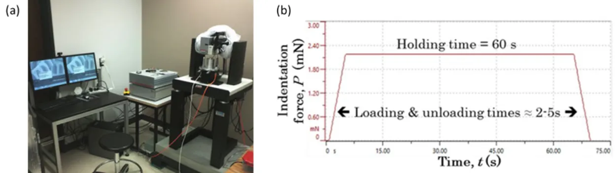
Figure 3.16 a) Typical load-depth curve of a nanoindentation test, b) Schematic representation of a nanoindentation test, adapted from [Sorelli et al., 2008]……….... 57 Figure 3.17 a) Appearance of the nanoindentador and accessories and b) controlled force sequence during the test (courtesy of William Wilson)…………... 58
Figure 3.18 a) Slump test and b) measurement of temperature in freshly mixed concrete………. 59
Figure 3.19 Aspect of loading apparatus and penetration needles for setting time tests………... 60
Figure 3.20 Compressive strength test (left) and measurement of deformations to determine the modulus of elasticity of concrete (right)………. 61
Figure 3.21 a) Proposed arrangement for migration of chlorine ions and b) penetration depth of chlorine ions………. 62
Figure 3.22 Appearance of PROCEQ Resipod Concrete Resistivity Meter (left) and Surface electrical resistivity measurement (right)………. 63
Figure 3.23 Accelerated carbonation chamber (left) and carbonation depth (right)…. 64 Figure 4.1 XRD patterns of pastes series AP with different minerals admixtures (dosage 20%) at 28 days……… 67
Figure 4.2 XRD patterns of pastes series AP with different minerals admixtures (dosage 60%) at 28 days……… 67
Figure 4.3 XRD patterns of pastes series AP with different minerals admixtures (dosage 20%) at 90 days……… 68
Figure 4.4 XRD patterns of pastes series AP with different minerals admixtures (dosage 60%) at 90 days……… 68
xiii
Figure 4.5 XRD patterns of pastes series BP with different minerals admixtures (dosage 20%) at 28 days………... 69 Figure 4.6 XRD patterns of pastes series BP with different minerals admixtures
(dosage 60%) at 28 days………... 69 Figure 4.7 XRD patterns of pastes series BP with different minerals admixtures
(dosage 20%) at 90 days………... 70 Figure 4.8 XRD patterns of pastes series BP with different minerals admixtures
(dosage 60%) at 90 days………... 70 Figure 4.9 Mineral admixtures dosage vs. CH content for series AP at 28 days……. 72 Figure 4.10 Mineral admixtures dosage vs. CH content for series AP at 90 days……. 72 Figure 4.11 Mineral admixtures dosage vs. CH content for series BP at 28 days……. 73 Figure 4.12 Mineral admixtures dosage vs. CH content for series BP at 28 days……. 73 Figure 4.13 Effect of curing time on CH content for series AP with mineral
admixtures dosages of 20%... 74 Figure 4.14 Effect of curing time on CH content for series AP with mineral
admixtures dosages of 60%... 74 Figure 4.15 Effect of curing time on CH content for series BP with mineral
admixtures dosages of 20%... 75 Figure 4.16 Effect of curing time on CH content for series BP with mineral
admixtures dosages of 60%... 75 Figure 4.17 Effect of W/B ratio on CH content for pastes with mineral admixtures
dosages of 20% (28 days)………. 76 Figure 4.18 Effect of W/B ratio on CH content for pastes with mineral admixtures
dosages of 60% (28 days)………. 76 Figure 4.19 Effect of W/B ratio on CH content for pastes with mineral admixtures
dosages of 20% (90 days)………. 77 Figure 4.20 Effect of W/B ratio on CH content for pastes with mineral admixtures
dosages of 60% (90 days)………. 77 Figure 4.21 Results of statistical nanoindentation tests for OPC system. a) Cluster
repartitions in the representation of indentation hardness (H) vs. indentation modulus (M) and b) Optical micrograph………
80
xiv
Figure 4.22 Results of statistical nanoindentation tests for B20NP system. a) Cluster repartitions in the representation of indentation hardness (H) vs. indentation modulus (M) and b) Optical micrograph………
81 Figure 4.23 Results of statistical nanoindentation tests for B60NP System. a) Cluster
repartitions in the representation of indentation hardness (H) vs. indentation modulus (M) and b) Optical micrograph………
82 Figure 4.24 a) Representation of relative intensities of calcium (ICa) and silicon (ISi)
for data points of OPC system after SNI-EDS analyses. b) Results of SNI-EDS analyses for OPC system represented by indentations modulus (M) vs. indentation hardness (H)………
84 Figure 4.25 Results of SNI-EDS analyses for the B20NP system, as represented into
three different axes: a) ICa, vs. ISi, b) IAl vs. ISi and c) M vs. H…………... 86 Figure 4.26 Results of SIN-EDS analyses for B60NP system: a) ICa vs. ISi, b) IAl vs.
ISi and c) M vs H………...
87 Figure 4.27 Distribution of hydrates obtained by chemical maps of the systems
studied: a) OPC, b) B20NP, c) B60NP and d) represents the magnified view of the rectangle in c)……….
89 Figure 4.28 Variations in the properties of cluster 1 (C-S-H, C-(A)-S-H) for the
systems OPC, B20NP and B60NP represented for the following variables: a) ICa vs ISi, b) ICa vs IAl, c) M vs. ISi and d) H vs. ISi…………..
91 Figure 4.29 Distribution of anhydrous particles on the analyzed surfaces as obtained
by chemical maps of the systems studied: a) OPC, b) B20NP and c) B60NP……….. 91 Figure 4.30 SEM image and EDS analyses of natural pozzolan particles……… 94 Figure 4.31 Compressive strength development for series A concretes (W/B = 0,45). 98 Figure 4.32 Compressive strength development for series B concretes (W/B= 0,35).. 99 Figure 4.33 Static modulus of elasticity for series A concretes (W/B = 0,45)……….. 100 Figure 4.34 Static modulus of elasticity for series B concretes (W/B = 0,35)……….. 101 Figure 4.35 Chloride migration coefficient (Dnssm) for series A concretes at 56 and
90 days (W/B = 0,45)……… 103 Figure 4.36 Chloride migration coefficient (Dnssm) for series B concretes at 56 and
xv
Figure 4.37 Relationship between the content of Portlandite (Ca(OH)2) and the chloride migration coefficient of the reproduced pastes from series A and B concretes………
104
Figure 4.38 Surface resistivity development for series A concretes, (W/B = 0,45)….. 105
Figure 4.39 Surface resistivity development for series B concretes, (W/B = 0,35)….. 106
Figure 4.40 Relationship between surface resistivity and Chlorine migration coefficient for all concretes mixtures (Series A and B)………. 107
Figure 4.41 Carbonation depths of Series A concretes……… 109
Figure 4.42 Carbonation depths of Series B concretes………. 109
Figure 4.43 Drying shrinkage of Series A concretes……… 111
Figure 4.44 Drying shrinkage of Series B concretes……… 111
Figure 4.45 Percentage of voids, Series A concretes at 90 days………... 113
Figure 4.46 Percentage of voids, Series B concretes at 90 days………... 114
Figure 4.47 Variation of the chloride migration coefficient according to the percentage of voids of Series A concretes at 90 days……… 115
Figure 4.48 Variation of the chloride migration coefficient according to the percentage of voids of Series B concretes at 90 days……… 115
xvi
List of Tables
Table 2.1 Indentation modulus of calcium silicates, calcium aluminate and calcium aluminoferrite present in Portland cement clinker [Acker, 2001]………
15 Table 2.2 Elastic modulus of CH and C-S-H obtained by nanoindentation……….. 15 Table 2.3 Classification of the two morphological entities of C-S-H as found in
the open literature [Constantinides and Ulm, 2004]………. 16 Table 2.4 Results of indentation where E is elastic modulus and H is hardness all
in GPa [Monadal et al., 2007]………... 17 Table 2.5 Hardness of CH and C-S-H obtained by nanoindentation………. 18 Table 2.6 Indentation modulus, hardness and C-S-H volume fraction [DeJong and
Ulm, 2007]………... 19
Table 2.7 Indentation modulus, hardness and volume of hydration products in undamaged concrete [Zadeh et al., 2013]………. 23 Table 2.8 Indentation modulus, hardness and volume of hydration products in
damaged concrete [Zadeh et al., 2013]………. 23 Table 2.9 Summary of indentation modulus of inner product and outer product in
GPa [Hu et al., 2014]……… 25 Table 2.10 Mechanical parameters of fly ash present in fly ash blended cement
pastes [Hu, 2014]……….. 26 Table 2.11 Summary of mechanical parameters of C-S-H gel [Hu, 2014]………….. 26 Table 2.12 Deconvolution results of the C-S-H phase [Hu and Li, 2015]…………... 27 Table 2.13 Average Ca/Si, Ca/(Si+Al), Al/Si ratios of the C-S-H phase using
SEM-EDS [Hu and Li, 2015]………. 28 Table 2.14 Results modulus mapping……… 29 Table 2.15 Results of permeability and chloride penetration [Seleem et al., 2010]… 33 Table 2.16 Strength of mixes relative to the control at each test age [Elahi et al.,
2010]……… 35
Table 3.1 Chemical composition and Physical properties of the Portland cement and mineral admixtures……… 40 Table 3.2 Pastes identification………. 45 Table 3.3 Mortars identification………... 45
xvii
Table 3.4 Concrete Mixtures composition; dry materials and the water include the
absorption of the aggregates, kg/m3……….. 48
Table 4.1 Compressive strength of mortars for series AM (W/B = 0,45)………….. 78
Table 4.2 Compressive strength of mortars for series BM (W/B = 0,35)………….. 79
Table 4.3 Results of SNI-EDS analyses of the OPC system: average indentation hardness (µH), modulus (µM) and volume fractions (π) for clusters of datapoints attributed to their predominant phases………. 85 Table 4.4 Results of SNI-EDS analyses of the B20NP system: average indentation hardness (µH), modulus (µM) and volume fractions (π) for clusters of datapoints attributed to their predominant phases………. 86 Table 4.5 Results of SNI-EDS analyses of the B60NP system: average indentation hardness (µH), modulus (µM) and volume fractions (π) for clusters of datapoints attributed to their predominant phases………. 88 Table 4.6 Fresh concretes properties……… 93
Table 4.7 Setting times of the concretes………... 96
Table 4.8 Compressive strength of concretes, Series A and B……….. 97
Table 4.9 Static modulus of elasticity for Series A and B concretes………. 100
Table 4.10 Packing densities of cementitious materials (pastes reproduced from the concretes studied) measured by wet packing method………... 102
Table 4.11 Resistance to chloride ingress based on non-steady state migration method [Nilsson, L. et al., 1998]………... 102
Table 4.12 Chloride ion penetration adopted from AASHTO TP 95-11……… 106
Table 4.13 Carbonation depths of Series A and B concretes……….. 108
1
Chapter 1. Introduction.
The hydraulic cement based concrete is the most used building material in the world after water. This material showed a better performance from a durability point of view compared to other building materials. In addition, it is now relatively easy to get the necessary ingredients for its manufacture. Today, despite its wide application in the development of general infrastructure, concrete producers have not been able to boost its production in a sustainable way, especially in developing countries. Consequently, it is still difficult to extend in a more efficiently way the service life of concrete. Nevertheless, in recent decades, important advances have been made in the production of concrete, starting from the simple concrete for general use, then high performance concretes, self-consolidation concrete and ultra-high performance concretes.
In general, the use of mineral admixtures has been well accepted since it has been demonstrated to provide several enhancements to the physical and mechanical properties of the concrete. The majority of these materials are industrial byproducts. They are desirable from the point of view of the environment and energy care and conservation, for the benefits they can offer to concrete, such as increased durability, improvement of the impermeability of concrete, enhancement of resistance to alkali aggregate reactivity, resistance to sulfates attack, etc.
The optimum amount of these mineral admixtures, either in addition to or as partial replacement of cement used to make concrete, should be established through testing in order to determine if these materials improve certain properties. An overdose or under dose can be harmful and cause unwanted effects because mineral admixtures react differently with different types of cement [PCA, 2008].
Fly ash, blast furnace slag, natural pozzolan and silica fume are the mineral admixtures most commonly used and are also known as supplementary cementitious materials. These materials have been widely used in producing concrete. Currently, due to their synergetic effect, concrete producers can combine two or more of these admixtures in order to optimize the physical and mechanical properties. Concrete mixtures using two cementitious materials are called binary blends whereas those with three mineral additions are called ternary blends.
2
However, while it is know that the use of mineral admixtures improves the physical and mechanical properties of concrete, there is still a lack of knowledge about the microstructure, and in recent decades, research work in this area has been made in order to produce efficient concretes from the durability viewpoint.
1.1 General context.
Nowadays, the challenge that civil engineering is facing is to create infrastructure in the context of sustainable development whit the use of construction materials at low cost and environmental impact. The Portland cement concrete is the construction material widely used in the world; unfortunately the Portland cement production releases to the atmosphere large amounts of CO2, which is one of the main greenhouse and global warming overall contributors on our planet [Damtoft et al., 2008; Lothenbach et al., 2011]. Therefore, in modern concretes, it is indispensable to use supplementary cementitious material that help to reduce the dosage of Portland cement. The majority of mineral admixtures are byproducts of industrial processes, which makes them even more desirable. Besides, most of them have proven to help improve the durability of concrete. On this point, last researches on the use these cementitious materials in concrete have revealed that these cementitious materials increase the impermeability of concrete, which has been attributed to a combined effect of microstructural densification and pozzolanic reaction leading to form secondary S-H; In other cases, increased formation of H was reported contributing to the increase of the durability of concrete. Regarding the C-S-H formation, which is the phase that has the greatest impact on the physical and mechanical properties of concrete, there have been large advances about it. However, most of the studies have been based only on Portland cement pastes or synthetic C-S-H [Richardson, 2004; Foley et al., 2012; Mendoza et al., 2015]. Few studies have been conducted on pastes with mineral admixtures and the results have been promising but contradictories. So, more studies are needed about the influence of mineral admixtures on C-S-H formation and the paste microstructure, themselves, this can allow understanding their effect on the mechanical properties of this phase and finally to know how they improve the permeability and durability of concrete.
3
1.2 Definition and objectives.
The probable influence of the use of supplemental cementitious material on C-S-H formation has not been studied in detail. So, in this project, the effect of mineral admixtures on the C-S-H formation will be studied in order to know how this material affect the physical and mechanical properties of this gel. This will help to understand the mechanism of concrete microstructure densification. This study will provide guideline of having more control on the concrete mix design based on the microstructure analysis in order to improve its permeability. This will result in concrete designs that are more efficient from the sustainabilitypoint of view because itwill take advantage more efficiently of these types of supplementary materials leading to prolonged service life of the structures.
1.2.1 Objectives.
The main goal of this investigation is to study the C-S-H formation and evaluate the permeability of concretes produced with two different mineral admixtures (MA). So, in order to fulfill this purpose, it is necessary to carry out the following specific objectives:
• Study the effect of MA on physical and mechanical properties of C-S-H formation with two different dosage (20% and 60%) foe each one.
• Study the effect of MA on concrete microstructure.
• Study the effect on durability and mechanical properties of concretes with MA microstructure based.
• Establish practical proportions to produce durable concrete incorporating MA under a scheme of sustainable development.
4
1.3 Thesis outline.
This research work was made with the collaboration between Universidad Autónoma de Nuevo León (UANL) and Université de Sherbrooke (UdeS) by means of an agreement of co-tutorship and dual-degree program.
The thesis is divided into five chapters. Following the introduction where the general context and the objectives are presented, Chapter 2 is giving an overview of the literature review. The materials and experimental program are detailed in Chapter 3. The chapter 4 is presenting the results and discussions. Finally, the conclusions and recommendations are developed in Chapter 5.
5
Chapter 2. Literature review.
2.1 Role of mineral admixtures in high-performance concrete.
High-performance concrete was developed in the eighties; its name was proposed because in addition to its low water/binder ratio, it also has other enhanced features such as higher consistency, higher modulus of elasticity, greater strength bending, lower permeability, higher abrasion resistance and durability [Aïtcin, 1998].
High-performance concrete is that which meets special performance specifications and requirements of uniformity that cannot always be achieved routinely by using components, mixing practices, placement and traditional curing [ACI 318]. In general, it can be said that these concretes are developed to meet certain characteristics in particular applications and environments and have a lower water/binder ratio than 0.42, which approaches the theoretical value suggested by Powers to ensure complete hydration of the Portland cement [Aïtcin, 1998]. The role of mineral admixtures in high-performance concrete production may be the following: to produce delays in the time of setting, resulting in lower and less intensive early contractions; to achieve better concrete docility using less water; to reduce the production costs of concrete; to reduce the heat of hydration, and to increase durability of concrete. The disadvantages would be a slow initial strength development, and depending on its fineness, a greater shrinkage when drying.
2.2 Concrete durability.
The durability of reinforced concrete, due to the presence of agents promoting deterioration in the environment depend much on concrete permeability [Sabir et al., 1998; ASTM C1585, 2004]. Three mechanisms can be used to describe the transport of fluids within the concrete: permeability, diffusion and absorption. Permeability is the measure of water flow under a pressure gradient, diffusion is the movement of ions due to the concentration gradient and absorption can be described as the ability of the materials to take water through capillary suction [Nethalath, 2006; Bentz et al., 2001].
6
Corrosion of steel reinforcement in concrete is a serious problem that civil engineers are facing these days, trying to keep up the infrastructures that are in the process of aging. The main causes of this phenomenon are chloride attack and carbonation. These two mechanisms do not attack the integrity of concrete, but they do affect its permeability; so, in this manner, both attacks promote corrosion.
2.2.1 Electrical resistivity.
One parameter of durability measured in concrete is the electrical resistivity; with this measurement, it can be evaluated the following characteristics of concrete: fresh and hardened stage, degree of curing, resistance to chlorine ions penetration and corrosion rate of steel reinforcement [Andrade and D’Andrea, 2011]. The measurement of electrical resistivity is a simple, non-destructive, reliable and rapid test method, which can also be used for quality control of concrete during construction [Sengul and Gjorv, 2008].
The resistivity test is a low cost and repeatable method that allows testing several times, therefore, changes in concrete properties can be monitored using the same samples. The strength of the concrete can be measured in a few minutes as no special preparations of specimens are needed. Portable hand-held and battery-operated resistivity measurement devices commercially available can be used both in laboratory and on-site.
Resistivity testing has been standardized recently by ASTM C1760, in which the method for bulk resistivity is defined. The measurement of surface resistivity using the Wenner four-electrode method has also been implemented [AASHTO TP 95-11]. Relationships have been established between the two-electrode method (bulk resistivity) and the four-electrode Wenner method, showing results that are congruent with each other. However, Wenner's method proved to be a simpler and faster method to monitor concrete quality control during construction [Sengul and Gjorv, 2008].
7
Figure 2.1 Schematic representation of four-electrode resistivity test (Wenner method) [Sengul and Gjorv, 2008]
Figure 2.2 Two-electrode testing on concrete cylinders (ASTM C 1760) [Sengul and Gjorv, 2008]
8
2.2.2 Chloride ions permeability.
Reinforcing steel corrosion induced by chlorides is the most important degradation process in reinforced concrete structures, which has very important economic and social consequences. There are two main sources for the ingress of chloride into concrete structures: seawater and deicing agents used in the winter.
There are two ways in which chlorides are present in concrete: as free chlorides and bonded chlorides. The total amount of chlorides is the sum of these two but only free chlorides can move and contribute with a chemical potential or concentration [Tang and Zhu, 2007].
Chlorides penetrates concrete mostly by diffusion in the water-saturated pores and they are transported through the pores due to their permeability or by suction. Chloride ingress is generally accompanied by physical and chemical bonds.
The movement of chlorides through the solution generally causes bonds that can significantly delay the process of penetration. The ability of concrete to link chlorides depends on the type of cementitious material and of its hydration products. It is also affected by other factors such as temperature and alkalis concentration [Tang and Zhu, 2007].
Since durability of concrete structures is of great importance, several methods have been proposed for measuring the penetration of chlorides. However, due to the complexity of this process, it has been difficult to reach to a general agreement about the election of a single test method.
For years, in the United States two methods have been used [ASTM STP 169D, 2006]: • ASTM C-1202 “Standard test method for electrical indication of concrete’s
ability to resist chloride ion penetration”.
• AASHTO T-277 “Rapid chloride permeability test”
In the Nordic countries there are three test methods developed by NORDTEST [Gjorv, 2014]:
• NT BUILD 443 “Concrete, Hardened: Accelerated Chloride Penetration”, based on a non-stationary diffusion state under high chloride concentrations.
9
• NT BUILD 355 “Concrete, Mortar and Cement Based Repair Materials: Chloride Diffusion Coefficient from Migration Cell Experiments”, based on a stationary diffusion state.
• NT BUILD 492 “Concrete, Mortar and Cement Based Repair Materials: Chloride Diffusion Coefficient from Non-Steady Migration Experiments”, based on a non-stationary diffusion state.
2.2.3 Carbonation.
Carbonation is a process of gaseous carbon dioxide diffusion with carbonated ions. Diffusion of the gas is faster than ions. Therefore, the carbonation rate depends on the internal humidity of the concrete. In dry concretes, carbon dioxide can penetrate to great depth, but there is not enough water to carry out the carbonation reaction. Therefore, there is an optimum moisture condition in which the carbonation rate is at its peak.
The carbonation rate will depend on how fast the carbon dioxide and/or carbon ions moves into the concrete and react with the cement paste. Factors affecting the carbonation progress in concrete structures are:
Humidity
Carbonation rate diminishes in very dry environments, as well as very humid and saturated ones. The maximum carbonation rate appears when relative humidity of concrete is between 60 and 80% [Largerblad, 2006]. The wetting and drying cycles also seem to accelerate the carbonation process.
Temperature
The rate of diffusion and carbonation increase as temperature does. Cementitious material content
Diffusion occurs inside the paste, and not in the aggregate. The amount of cementitious material does not affect the carbonation rate as long as the water/binder rate is maintained constant: that is, a larger amount of paste, but with the same porosity, will have the same carbonation depth, but with a larger volume of carbonated paste
10 Concrete quality
A higher water/binder ratio and a higher hydration grade produce a dense concrete with lower porosity. This will also result in dense carbonation products and consequently a reduction in carbonation. It is well known that a dab curing will result in a higher carbonation rate, possibly due to a diminished in the rate of hydration.
Type of cement and pozzolans effect
The use of blended cement is becoming more common every day. These cements are composed of Portland cement clinker, gypsum, limestone, blast furnace slag, fly ash, silica fume, etc.
As for fly ash, its pozzolanic reaction will cause a decrease in the content of calcium hydroxide and an increase in the content of C-S-H. A lower amount of calcium hydroxide will increase the rate of carbonation; however, the increase in the amount of C-S-H and its effect on the carbonated paste must be taken into account [Largerblad, 2006].
2.2.4 Drying shrinkage.
The shrinkage of concrete is a concern for its impact on its durability. The useful life of the structure can be significantly reduced to cause of the cracks induced by this effect (figures 2.3 and 2.4). Commonly the retraction is attributed to the drying of concrete over long periods of time, although recent studies have focused on problems at an early age or drying in a plastic state [Holt, 2001].
The most common solution to reduce volume changes at an early age is to avoid drying by proper handling of the concrete during the first hours after placement. It is imperative that the curing starts immediately after and for proper methods [Holt, 2000].
11
a http://opc.com.mx/boletines/grietas_plasticas.html b http://www.xypexman.com/projects/proj-lagley.html
Shrinkage of concrete takes place in two different periods; at an early age and at a later age. Early age is understood as the first day (first 24 h after mixing) when the concrete is hardening and begins its hardening. Later or long-term age refers to an age greater than 24 hours. During the later age, the concrete is demolded and the retraction measures are carried out. The shrinkage at a later age is typically considered in structural design.
Long-term shrinkage has been measured in concrete practice for many years. In general, it is measured from 24 hours after mixing or at the time of demolding. It is measured in prismatic specimens of normalized dimensions registering the change in length over time, according to standards such as ASTM C157 or RILEM CPC 9.
The drying shrinkage refers to the reduction of the volume of concrete resulting from a loss of water. Initially, according to the aggregate particles more heavy settle free water escapes to the concrete surface as bleed water. This bleeding water can evaporate from the surface, causing the rise of more water inside the concrete by capillary suction.
The most common situation that results from drying shrinkage at an early age is the appearance of surface cracks. There can also be a cracking problem due to the water suction that can originate the form or material on which the concrete structure is displaced [Mindess and Young 2007]. On the other hand, if the rate of bleeding exceeds the rate of evaporation this excess water will act as a curing film. In this case, there will be no drying contraction at an early
Figure 2.3 Early drying shrinkage on a slab roof. a
Figure 2.4 Reparation of shrinkage cracks in a wall. b
12
age, since there is enough water on the surface that allows evaporation without extracting water from the capillary pores.
The mechanisms that cause retraction by drying are dependent on the size of the pores [Mehta and Monteiro, 2006]. The capillary pores are the spaces occupied by the excess of water, which are reduced during the hydration reactions of the cement; in this way, the existing relative humidity will be correlated with the size of the capillary pore inducing simultaneous stress and retraction [Janz, 2000].
2.3 C-S-H formation.
Concrete has a highly heterogeneous and complex microstructure made of three main components: hydrated cement paste, aggregates and interfacial transition zone between cement paste and aggregates. Due to this heterogeneity, each of these components has been individually studied in order to improve and control the physical and mechanical properties of this composite material [Mehta and Monteiro, 2006].
The main products of Portland cement hydration are calcium silicate hydrates (C-S-H) followed by calcium hydroxide or portlandite (CH). Other phases formed as a result of the hydration of the cement are hydrated aluminates and sulfo-aluminates AFm and AFt, whose formation depends on the composition of cement, the time and conditions of hydration.
C-S-H is a nearly amorphous material and forms up to about 60% of the paste. The hyphens in C-S-H indicate indefinite stoichiometry and the hydrate is sometimes referred to as “C-S-H gel”. The C-S-H is produced along with calcium hydroxide in the chemical reaction of the silicate phases (β-C2S and C3S) with water.
The molar ratio of CaO to SiO (C/S ratio) in C-S-H is one of the main parameters in defining and controlling the properties of a calcium silicate hydrate system. This value varies from 1.2 to 2.3 in hydrates silicate phases and has an average of about 1.75. The C-S-H system may be divided into low and high lime content categories partitioned by the C/S ratio of about 1.1 where chemical and physical properties change noticeably [Raki et al., 2010].
It is widely believed that the fundamental properties of concrete such as strength, ductility, early rheology, creep and shrinkage, fracture behavior, durability, etc. are affected by
13
material properties at nano level [Corr and Shaha, 2005]. Thus, the nanostructure of C-S-H has been the subject of a lot of research. However, the exact structure of C-S-H is not known yet. So, several models have been proposed in order to understand and establish relationships between its structure and properties of concrete.
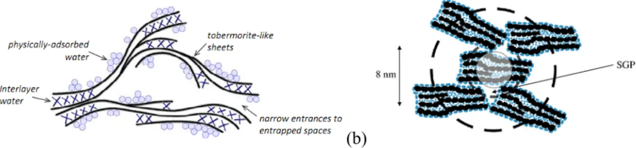
Among the models that have been developed to explain the above, we present two that we consider to have a watershed in the understanding of nanostructure and its effect on the properties of concrete (Figure 2.5). The Feldman and Sereda model suggests that the C-S-H is similar to clay particles, forms a three dimensional assemble of layer silicate sheets which locally tend to form parallel network groups with entrapped water and pore space [Feldman and Sereda, 1968 and 1970]. Jennings model suggests that the C-S-H structure is a colloidal network gel; the smallest distinct units of C-S-H are globules just under 5 nm in the smallest dimension, which pack together in two distinct structures called high density (HD) and low density (LD) of C-S-H. Furthermore, this model also tries to explain the implications of shrinkage and creep of the concrete [Jennings, 2003; Thomas and Jennings, 2006; Jennings, 2008 and Constantinides, 2013].
(a) (b)
Figure 2.5 C-S-H models proposed by a) Feldman and Sereda and b) Jennings colloidal model.
Moreover, Richardson has detected the existence of two different structures in the C-S-H gel. Less dense morphology mainly in the space originally filled by water and other more dense morphology mainly in the space originally occupied by cement particles. He named the two morphologies of C-S-H gel as outer product (OP) and inner product (IP) respectively (Figure 2.6) [Richardson, 1999, 2000, 2004 and 2008].
14
Figure 2.6 A TEM micrograph showing IP and OP C-S-H [Richardson, 2000].
Although, there has been many advances in the field of nanoscience, further investigation is required in order to develop more durable concretes that are friendly to the environment too. In this sense, this project we will study the effect of natural pozzolan on the C-S-H formation in order to know how these materials provide more impermeable concrete.
2.4 Physical and mechanical properties of C-S-H.
Typical concrete consist of ordinary Portland cement (OPC), fillers such as sand, coarse aggregates, admixtures and water. This combination of materials allows concrete to be produced in a fluid form that can be pumped and molded. The chemical reactions and resulting products produced when cement is mixed with water create a material that is highly complex [Davydov et al., 2011]. The principal component, C-S-H gel, has a local structure of a precipitate with nanoscale features that are difficult to model and understand. Over the last years, the mechanical properties of C-S-H gel have been determined by nanoindentation technique, and statistical analyses have been used to deconvolute these mechanical properties of individual phases in hardened cement pastes. Thus in this method, it is not necessary to know exactly the location or material phase where each nanoindentation test is performed [Ulm et al., 2007].
Velez et al., (2001) were among the first to determine the physical and mechanical properties on pure constituents of Portland cement clinker by nanoindentation having satisfactory and congruent results with Acker, (2001) (Table 2.1). Following their research, the possibility of studying the hydration products of the cement paste was opened.
15
Table 2.1 Indentation modulus of calcium silicates, calcium aluminate and calcium aluminoferrite present in Portland cement clinker [Acker, 2001].
Constituent E (GPa) Reference C3S 135 ± 7 Velez et al. 135 ± 7 Acker C2S 130 ± 20 Velez et al. 140 ± 10 Acker C3A 145 ± 10 Velez et al. 160 ± 10 Acker C4AF 125 ± 125 Velez et al.
One of the first papers about the mechanical properties of C-S-H using nanoindentation technique was Constantinides and Ulm (2003 and 2004). They studied Portland cement pastes with water/cement ratio of 0,5. The average values of modulus of elasticity obtained were similar to those reported by Acker, (2001) who studied ultra-high performance concrete with very low water/cement ratio and with admixtures. For this reason, the results of Constantinides and Ulm suggested that mechanical properties of C-S-H were intrinsic (Table 2.2). Another important aspect of this research was that the volume fractions could be determined by nanoindentation corresponding to a percentage around 70% for LD S-H and 30% for HD C-S-H (see Figure 2.7), corroborating what was previously established by other authors about the existence of two different forms of C-S-H (Table 2.3).
Table 2.2 Elastic modulus of CH and C-S-H obtained by nanoindentation.
Elastic modulus (GPa) Reference CH 38.0 ± 5.0 Constantinides and Ulm
36.0 ± 3.0 Acker
HD C-S-H 29.4 ± 2.4 Constantinides and Ulm 31.0 ± 4.0 Acker
LD C-S-H 21.7 ± 2.2 Constantinides and Ulm 20.0 ± 2.0 Acker
16
Figure 2.7 Results obtained by nanoindentation. Two types of C-S-H are identified: LD and HD. % indicates volumetric proportions by measuring the area under the curves
[Constantinides and Ulm, 2004].
Table 2.3 Classification of the two morphological entities of C-S-H as found in the open literature [Constantinides and Ulm, 2004].
Classification Reference
Inner product - Outer product Taplin (1959), Groves (1987), Richardson (1999) Middle product – Late product Scrivener et al. (1985), Taylor (1997)
Phenograins – Groundmass Diamond and Bonen (1993)
Low density – High density Jennings (2000), Tennis and Jennings (2000)
Mondal et al., (2007) studied cement pastes (ordinary Type I Portland cement) manufactured with a water/cement ratio of 0,45. The age of the samples was 3 years. A Hysitron Triboindenter was used to determine the nano mechanical properties of C-S-H. They found that the elastic modulus could be divided in three different groups where values are decreasing with the distance from unhydrated particle (Figure. 2.8). The elastic properties were evaluated using the Oliver-Phar method, and the elastic modulus and hardness reported by them were similar to those reported previously (Table 2.4). They did not report result about the volume fraction, but they reported that the images by the AFM of C-S-H in hardened cement paste showed nearly spherical particles.
17
Figure. 2.8 Change in modulus of C-S-H with the distance from unhydrated particle [Mondal et al., 2007].
Table 2.4 Results of indentation where E is elastic modulus and H is hardness all in GPa [Monadal et al., 2007].
Constantinides and Ulm (2007) investigated the mechanical properties of C-S-H by using nanoindentation tests with the intention to validate this technique. For this purpose, they developed hundreds of nanoindentation tests in white cement pastes (same cement studied by Thomas and Jennings in 2002), with water/cement ratio of 0.5. The obtained values of Modulus of Elasticity of HD C-S-H and LD C-S-H were 29.1 ± 4.0 GPa and 18.2 ± 4.2 GPa respectively. According to the authors, both values were in excellent agreement with results of Acker and themselves in 2004 (Table 2.2). The hardness values obtained for HD and LD of C-S-H with the deconvolution technique were very much consistent with the results of Acker (Table 2.5).
18
Table 2.5 Hardness of CH and C-S-H obtained by nanoindentation.
Hardness modulus (GPa) Reference
CH 1.35 ± 0.5 Acker 1.31 ± 0.23 Constantinides et al. HD C-S-H 0.9 ± 0.3 Acker 0.83 ± 0.18 Constantinides et al. LD C-S-H 0.8 ± 0.2 Acker 0.45 ± 0.14 Constantinides et al.
In regard to volume fraction of LD and HD C-S-H, they found that the LD C-S-H makes up around 65% of the total C-S-H, having a good agreement with previous results too (Fig. 2.1).
However, what seems to be the most important finding of this study was that both phases (LD C-S-H and HD C-S-H) exhibited a unique nanogranular behavior, which is driven by particle to particle contact forces rather than mineral properties. It is argued that during the hydration reactions, C-S-H nanoparticles are precipitated generating contact surfaces and contact points and creating in the course of this process a material which behavior is driven by contact forces. Thus, the estimated packing densities of the LD C-S-H of 0.63 and 0.76 for HD C-S-H almost coincide with limit packing densities of spheres. The LD C-S-H packing density almost coincide with the random packing density of spheres of 0.64 and HD C-S-H packing density almost coincide with the densest possible spherical packing in three dimensions of 0.74. Thus, it confirms that the morphology of the C-S-H has two characteristic packing modes one being an unstructured order (LD C-S-H) and other with a highly structured order (HD C-S-H) and its impact on the mechanical properties of LD C-S-H and HD C-S-H.
Due to advances in nanotechnology area, DeJong and Ulm (2007) studied the effect of elevated temperature on the nanogranular behavior of C-S-H in order to know what is causing the damage on Portland cement exposed to high temperatures. To achieve this, DeJon et al. conducted nanoindentation and thermogravimetric tests in Portland cement Type I pastes with w/c = 0.5. The temperatures employed in this study ranged from 20 to 1000 oC in three stages. The results of DeJong and Ulm confirm the existence of two structurally distinct but compositionally similar C-S-H phases known as LD C-S-H and HD- C-S-H, but the principal thermal deterioration of C-S-H properties occurs above 200 oC (Figure. 2.9). Regarding the
19
volume fraction of the C-S-H, the relative volume proportion of the LD C-S-H and HD C-S-H practically do not change with exposure to high temperatures (Table 2.6).
Figure 2.9 Summary of nanoindentation results. The bars at each point represent the standard deviation obtained with the deconvolution technique [DeJong and Ulm, 2007].
Table 2.6 Indentation modulus, hardness and C-S-H volume fraction [DeJong and Ulm, 2007].
Němeček (2009) studied the effect of load application on the evaluation of elastic properties of C-S-H using nanoindentation technique. For this purpose, he made pastes of white cement with water/cement ratio of 0,5, and cured the samples for two months. He prepared two series of experiments. The first was applied load with no dwell period, and the second one was applied load with dwell period. He found that the creep affect principally the hydrated phases. The final values of modulus at 20 mN were practically the same for both types of load (Figure 2.10). The elastic properties were obtained according to the Oliver-Phar methodology and were reported of 28.2 ± 4.4 GPa for “O” series and 26.9 ± 1.8 GPa for “C” series. These results were in good agreement with those reported by Constantinides and Ulm (2007).
20
Figure 2.10 Indentation modulus for hydrated phases of cement paste. Thin lines represent “O” series with increasing loading cycles without a dwell period at the peak. Thick lines represent “C” series tested by cyclic loading to the same load with a 120 s dwell period at the
peak [Němeček, 2009].
So far, the existence of LD C-S-H and HD C-S-H phases and their mechanical properties, as well as the relationship between these mechanical properties of C-S-H and packing density respectively was well established. Due to concerns to know if the packing densities, gel porosities and volume fraction of C-S-H can be modified by varying the substochiometric conditions, Vandamme et al. (2010) carried out a study on cement pastes with w/c ratios ranging from 0.15 to 0.4 with and without heat treatment. Cement pastes were prepared using an alite rich cement at w/c = 0,15, 0,20, 0,30, 0,35 and 0,4. The casting and curing temperatures were 20 oC. Five other samples were prepared at w/c = 0,15, 0,20, 0,25, 0,30 and 0,35, and at the age of 48 hours, they were subjected to a heat treatment at 90 oC for 48 hours.
Among the findings, it was shown that the values of Modulus of LD and HD of C-S-H of the pastes that did not receive heat treatment were consistent with previous results. In addition, a new phase was detected which they appointed Ultra-high-density (UHD). The results of modulus and hardness in pastes that were treated thermally were quite similar to pastes that did not receive this treatment, thus confirming that the mechanical properties of C-S-H are intrinsic and not dependent on mix proportion, heat treatment, etc. Furthermore, the difference in modulus and hardness values between LD C-S-H, HD C-S-H and UHD C-S-H are related to packing densities of these phases (Figure 2.11).
21
Figure 2.11 Results from deconvolution of five pastes without heat treatment [Vandamme et al., 2010].
Concerning to the volume fraction of C-S-H, they found that in the pastes that did not receive heat treatment, the volume fraction of LD C-S-H is raised by increasing the w/c ratio and HD C-S-H volume decreased. The volume fraction of UHD C-S-H remained nearly unchanged (Figure 2.12). Moreover, the heat treatment favored the increase in HD and UHD of C-S-H (Figure 2.13).
Figure 2.12 Volume fraction distribution without heat treatment: a) volume fractions of the cement paste composite, b) volume fraction of hydration phases. In x axis w/c ratio by mass
[Vandamme et al., 2010].
Figure 2.13 Effect of heat treatment on volume fraction distribution: a) volume fractions of the cement paste composite, b) volume fraction of hydration phases. In x axis w/c ratio by mass
22
Sorelli et al. (2008) were among the first researchers to carry out a study on nanoindentation tests on samples of ultra-high performance concrete. They took samples from bridge plates for bending tests. The concrete was made with a water/binder ratio between 0.19 and 0.21. The ingredients used for manufacturing this concrete were cement CEM Type I, high-range water reducer admixture, silica fume, quartz powder, silica sand and steel fibers. At sixth day after casting, the material was heat treated for 48 h at temperature of 90 oC at relative humidity of 90 %. The age of nanoindentation tests were about 3 years.
The mean values of the indentation modulus of LD and HD C-S-H phases were 19.7 GPa and 34.2 GPa respectively, which were similar with respect to those reported in previous studies. Regarding the values of hardness, HD C-S-H was 1.36 GPa and slightly greater than the values reported previously. Finally, it was observed that the C-S-H matrix of ultra-high performance concrete is mainly composed of HD C-S-H, and its volume fraction was about 86%.
Sakulich and Li (2011) conducted nanoindentation tests on engineered cementitious composites. They prepared three different mixes; the used materials were Portland cement Type I, fine silica fume sand, fly ash Type F, high range water admixture, carbon black, single-walled nanotubes and polyvinyl alcohol fibers (PVA fibers). The water/binder ratio was 0,267 for all mixes. They did not detect any differences between LD and HD of C-S-H. They only reported the modulus value of Quartz, PVA fibers and unreacted fly ash whose value was 78.3 ± 14 GPa.
Having as antecedent that the concrete strength incorporating ultra-fine cementitious materials such metakaolin or silica fume is typically reported lower than normal concrete, while other supplementary cementitious materials (SCM), including fly ash and slag, result in similar or better behavior to high temperatures compared to normal concrete [Tylor, 1997; Herts, 1992; Poon et al., 2001]. Zadeh et al. (2013) studied concretes with different percentages of fly ash and slag exposed to fire-damage (300 oC) in order to investigate the changes on the C-S-H formation by using nanoindentation tests. The concretes studied were manufactured with Portland cement Type II and it replacement rates of 20 % fly ash class F, 60 % fly ash class F and 60 % slag cement grade 100 by mass. The water/binder ratio for the three concretes was 0,45.
23
With respect to undamaged concretes, the values for indentation modulus of LD C-S-H and HD C-S-H phases were similar to those reported in previous papers. However, the indentation hardness was higher compared to the values found in the literature. In regard to the volume fraction, there is no well-defined tendency, but it seems that the use of SCM decreases the volume of LD C-S-H (Table 2.7).
Table 2.7 Indentation modulus, hardness and volume of hydration products in undamaged concrete [Zadeh et al., 2013].
The modulus values of HD C-S-H phase in damaged concrete samples seems not be affected. However, the results on LD C-S-H phase indicate that these were affected by fire because they showed lower values. The same pattern was presented in hardness as volume fraction of LD C-S-H and HD C-S-H (Table 2.8).
Table 2.8 Indentation modulus, hardness and volume of hydration products in damaged concrete [Zadeh et al., 2013].
24
Liu et al. (2013) studied Portland cement pastes blended with ground granulated blast furnace slag. The cement was replaced by 30 % and 70 % of this slag by mass and the w/c ratio of the pastes was 0.4. Nanoindentation tests for 3 days, 90 days and one year were conducted. Once again, the elastic modulus values of LD C-S-H and HD C-S-H were similar to those reported in previous studies.
About the volume fraction results, the volume of LD C-S-H was gradually reduced and the volume fraction of HD C-S-H increased with the prolongation of hydration age. Likewise, the volume of LD C-S-H decreased and HD volume raised as slag consumption increased. According to the results of this paper, the micromechanical properties of C-S-H were not affected by their Ca/Si ratios. The hardness results were not reported.
In order to improve the understanding of the microstructures of C-S-H in cementitious composites through studying their physical and mechanical properties, Hu and collaborators (2014) studied the mechanical properties of C-S-H gel present in cementitious composites using the nanoindentation technique. They manufactured five mixtures with different mix proportions: two pastes mix with water/cement ratios of 0.23 and 0.40 and three mortar mix with water/ cement ratios of 0,23, 0,35 and 0,53.
In this study, they detected four distinct phases, which they named 1) Very porous S-H gel (VP S-S-H), 2) Outer product S-S-H gel (OP S-S-H), 3) Inner product S-S-H gel (IP C-S-H), and 4) Crystalline phase (Figure 2.14).
Figure 2.14 Probability distribution of indentation modulus of C-S-H/CH composites present in cement paste matrix [Hu et al., 2014).
![Table 2.4 Results of indentation where E is elastic modulus and H is hardness all in GPa [Monadal et al., 2007]](https://thumb-eu.123doks.com/thumbv2/123doknet/3049304.86000/36.918.248.699.114.374/table-results-indentation-elastic-modulus-hardness-gpa-monadal.webp)
![Figure 2.9 Summary of nanoindentation results. The bars at each point represent the standard deviation obtained with the deconvolution technique [DeJong and Ulm, 2007]](https://thumb-eu.123doks.com/thumbv2/123doknet/3049304.86000/38.918.203.728.215.393/summary-nanoindentation-represent-standard-deviation-obtained-deconvolution-technique.webp)
![Figure 2.11 Results from deconvolution of five pastes without heat treatment [Vandamme et al., 2010]](https://thumb-eu.123doks.com/thumbv2/123doknet/3049304.86000/40.918.145.798.105.359/figure-results-deconvolution-pastes-heat-treatment-vandamme-et.webp)
![Table 2.8 Indentation modulus, hardness and volume of hydration products in damaged concrete [Zadeh et al., 2013]](https://thumb-eu.123doks.com/thumbv2/123doknet/3049304.86000/42.918.133.809.809.1013/table-indentation-modulus-hardness-hydration-products-damaged-concrete.webp)
![Table 2.16 Strength of mixes relative to the control at each test age [Elahi et al., 2010]](https://thumb-eu.123doks.com/thumbv2/123doknet/3049304.86000/54.918.269.672.698.877/table-strength-mixes-relative-control-test-age-elahi.webp)