MODELING OF LOWER LIMBS FOR VIBROTACTILE COMPENSATION
Martin J.-D. Otis, Guillaume Millet, Stephane Beniak, and Jeremy R. Cooperstock
McGill University, Montreal, Canada
SUMMARY
A rehabilitation device with a vibrotactile actuator is designed for analysis of slipping behaviour on different surfaces. However, the coupling between a subject's lower limbs and the device reduces the accuracy of the ground simulation. A real-time algorithm is developed, based on an FFT filter-bank and a rheological limb model, which compensates for lower limb effects on vibrotactile signals.
INTRODUCTION
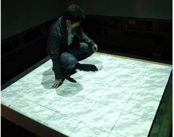
The aging of our population motivates the study and analysis of lower leg slipping behaviour on different surfaces, characterized by their coefficients of friction. Our specific interest involves experimental studies to understand how vibration influences human perception of friction on different surfaces. To facilitate such work, we developed a device, illustrated in Fig. 1, that includes a vibrotactile actuator to generate the vibration felt under the foot when walking on various materials, such as ice, snow or sand. The design involves tradeoffs in terms of the simulation of friction and fidelity of the subject's experience.
Of particular importance for perception studies, a mechanically transparent device is required to maximize the accuracy of the synthesized ground properties. However, coupling between user impedance of the lower limbs and the dynamics of the mechanical device can interfere with its transparency, thereby reducing the accuracy of the simulation. Transparency in haptics is defined by the capacity to cover the range of our perception, by producing vibration of high fidelity over a wide bandwidth of frequencies. To compensate for user effects on vibrotactile signals, we present a real-time algorithm based on a polyphase network implementation of an
FTT analysis-synthesis filter-bank and rheological modeling of lower limbs.
A previous study demonstrated that we could compensate for the structural properties of the tile, obtaining a flat response in the desired frequency bandwidth [1]. A 14-order FIR filter was designed for this static compensation. By inverting this filter, and applying it to all subsequent outputs of the actuator, we obtain a significantly corrected frequency response. In order to improve the results obtained with this filter and avoid issues of latency and stability, it is also possible to use a uniform and warped low delay filter-bank equalizer such as in speech enhancement applications [2]. However, this static compensation was found to be insufficient, prompting our research to explore the alternative of a dynamic compensation system, which extends the usable frequency range of the vibrotactile signal used for simulating ground properties from 40 to 1024 Hz.
Figure 1: Snow surface simulation in our virtual environment.
MECHANICAL DESIGN
The mechanical design has been presented in previous work [1]. Our initial prototype, which adds a variable-friction mechanism to enable the reduction of the coefficient of friction, is shown in Fig. 2. A Clark Synthesis vibrotactile actuator (model TST429-Platinum) and an accelerometer (model ADXL 305) are mounted under the tile. Signal generation and acquisition is performed with a National Instruments USB NI-6218. A SURE Electronics audio amplifier is used to drive the actuator. Four force sensors are located at each corner of the tile under an elastomer to monitor the user action. All the mechanical parts, which are used for the simulation of coefficient of friction absorb spectral energy different from that of the tile, thus justifying the design of a compensation algorithm.
LOWER LIMBS MODELING
A polyphase network implementation of an FTT analysis-synthesis filter-bank [2] is first used to equalize the response of the unloaded device in a static configuration. A second-order model of the skin and the leg Zc is used for the
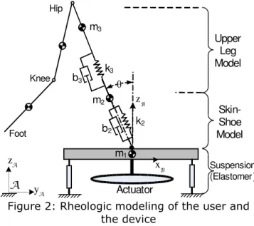
lower limbs, and is placed in cascade with the filter bank as described in Fig. 3. This model was used for predicting the kinematics and dynamics of a walker in [3]. Also, this model comes from two studies on the leg and skin parameters given respectively in [4] and [5]. The studies described the skin and the leg with two second order systems. For simplicity, the upper leg is modeled with a first order low-pass filter and the skin, along with the shoe is simplified with a resonant second order high pass filter. This model, described by the following equations, and illustrated in Fig. 2, reduces the number of finger parameters compared to the Kern model (in grasping application):
(1)
(2)
(3)
In the above,
g
2 comes from the sensorgains and is fixed at 0.005. The three values,
b
3/k
3,k
2/m
2 andb
2/m
2, must be evaluatedwithin an optimization procedure. It can be noted that the elastomer suspension element under the tile acts like a notch filter with a resonant frequency near 20 Hz, which is very near the characteristic of the leg. This elastomer and the leg are then simplified in one low-pass model with the parameter
b
3/k
3.Figure 2: Rheologic modeling of the user and the device
ALGORITHM IMPLEMENTATION The filter bank adaptively adjusts the gain with weighted spectrum coefficients for each sub-band filter as a function of the static configuration of the tile. The second component dynamically corrects the frequency response of the moving user with the rheological model as shown in Fig. 3. The main challenge here is to simplify the computations involved in order to minimize hardware costs while maintaining a reasonable level of fidelity. To this end, we can do away entirely with the real-time correction algorithm and instead provide a preset equalizer for any specific user based on his or her precomputed parameters. Thus, by studying a variety of individuals and constructing a representative database of mappings from parameters to corresponding correction equalizers, the entire correction system can function via a simple lookup table, interpolating any parameter sets in between those from known users [6].
Upper Leg Model Skin-Shoe Model Suspension (Elastomer ) θ m1 m3 m2 b2 b3 k2 k3 zA yA A zB Foot Knee Hip xB Actuator
Ground simulator Haptic device User RTAI User Interface Adaptive Equalizer Main computer p(t) , f(t) NI-6218 USB Audio Vibrotactile Identification Zc(z)
Figure 3: Vibrotactile compensation algorithm RESULTS
A sweep frequency response is achieved over the bandwidth range of 40 to 1024 Hz, which corresponds to the maximal vibrotactile response of the skin [5]. Under 40 Hz, the device does not exhibit a significant response. The accelerometer provides the magnitude A of the vibrations. The unloaded response gives the spectral weighting w for the equalizer, which is computed iteratively with equations (4) and (5):
(4) (5) where and are the mean values. Fig. 4 shows these frequency responses for the unloaded device with the spectral weighting applied by the filter bank equalizer. Two or three frequency sweeps are required to obtain a reasonably accurate, flat frequency response over the desired bandwidth since moderate intensity of vibration threshold ranges from 0.45 to 3 dB [7]. For each pass, the deviation from a flat response decreases from 15.3, 0.90 and 0.28 dB, respectively, with the final error likely due in large part to accelerometer noise.
Figure 4: Frequency sweep of the unloaded device with the filter bank equalizer
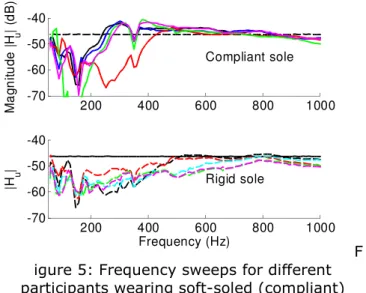
Ten participants, between 20 and 35 years of age, were then asked to stand on the device with two different types of shoes: compliant and rigid sole. As seen in Fig. 5, the effect of the type of sole is important. The soft sole allows the tile to vibrate more freely and can cause it to enter resonance in mid-range frequencies, between 400 and 600 Hz. In contrast, the rigid sole constrains the tile movement over a wider bandwidth as the weight of the user increases.
200 400 600 800 1000 -70 -60 -50 -40 Compliant sole M a g n it u d e | H u | (d B ) 200 400 600 800 1000 -70 -60 -50 -40 Rigid sole |H u | Frequency (Hz) F igure 5: Frequency sweeps for different participants wearing soft-soled (compliant)
shoes (upper graph) and rigid soles (lower graph).
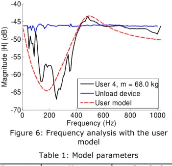
The rheological model presented in Equation (3) is then fitted with a trust-region-reflective algorithm for each magnitude of the frequency response, for which the results are shown in Fig. 6. Upper and lower bonds on each parameters (b3/k3 , k2/m2 and b2/m2) are used to
avoid divergence or meaningless solutions. Table 1 shows the mean and standard deviation for the three parameters for the participants. It should be noted that the cutoff frequency of the leg is lower than 20 Hz and our device can only perform adequately over 40 Hz. Also, the noise below 200 Hz is a characteristic of the actuator coupled with the mechanical components and is also observed in the unloaded response of Fig. 4. This behaviour cannot be compensated for with a non-adaptive filter-bank equalizer. Nevertheless, this first experiment shows that the model can be used to compensate for the effect of the limbs, whatever the respective sole, on the spectral magnitude.
0 200 400 600 800 1000 -55 -50 -45 -40 -35 Frequency (Hz) M a g n it u d e | H | (d B ) pass 1 pass 2 pass 3
The final step is to utilize the measured force applied by the user and the accelerometer data to implement an identification algorithm that compensates for the model in real-time. Similar online estimation of human impedance was previously investigated for human-robot interaction stability for movement of the leg [8] and the vibrotactile signal applied to fingers during grasping [6,9]. In this manner, the transfer function of the limb can be inverted and used as described in Fig. 3.
Figure 6: Frequency analysis with the user model
Table 1: Model parameters
Parameter Mean Standard
deviation b3/k3 k2/m2 b2/m2 0.0037 5.8x10⁶ 2402 0.0016 4.1x10⁶ 1.5x10³
CONCLUSION AND FUTURE WORKS We presented a simple compensation algorithm for haptic transparency of our vibrotactile device, which synthesizes vibrations corresponding to different types of grounds with variable friction properties. Using a filter-bank equalizer and a rheological model allows for compensation of the effects of the device, the lower limb, and the shoe.
The table-based dynamic compensation presented here is only an approximation. More elaborate techniques, such as the filter-bank adaptive equalizer, exploiting short-time DFT/IDFT could be used to reduce the error of the model. Our future work is concerned with a
strategy for adaptively changing the spectral weights in real time as the user walks on the device. Further investigation must be conducted on the dynamic effect of the mechanism itself. At present, the position of the contact point changes the apparent stiffness and damping at this point modifies the frequency response of the tile. In addition, acceleration must be evaluated at the contact point since the movement of the tile differs depending on where the force constraint is applied.
ACKNOWLEDGEMENTS
This research was supported by a grant from the MDEIE of Quebec for the European 7th
Framework Programme project Natural Interactive Walking (NIW, no. 222107). The authors gratefully acknowledge this support and thank Yon Visell for useful discussions.
REFERENCES
[1] Y. Visell and J. R. Cooperstock, “Design of a Vibrotactile Display via a Rigid Surface,” Haptics Symposium, IEEE, pp. 133-140, March 2010.
[2] Heinrich W. Lollmann, and Peter Vary, “Uniform and warped low delay filter-banks for speech enhancement,” Speech Communication, Elsevier, vol. 49 (no. 7,8), pp. 574-587, 2007.
[3] Marcus G. Pandy and Necip Berme, “Synthesis of human walking: A planar model for single support,” Journal of Biomechanics, vol. 21 (no. 12), pp. 1053 -1060, 1988.
[4] M. H. Pope, H. Broman and T. Hansson, “Impact response of the standing subject - a feasibility study,” Clinical Biomechanics, vol. 4 (no. 4), pp. 195-200, 1989.
[5] Lundstrom, R., “Local vibrations-mechanical impedance of the human hand's glabrous skin,” Journal of Biomechanics, vol. 17 (no. 2), pp. 137-144, 1984. [6] J. Fiene, K. J. Kuchenbecker and G. Niemeyer,
“Event-based haptic tapping with grip force compensation,” Haptics Symposium, IEEE, pp. 117-123, March 2006.
[7] J. C. Craig, “Difference threshold for intensity of tactile stimuli,” Perception and Psychophysics, vol. 11, pp. 150–152, 1972.
[8] Y. Tanaka, T. Onishi, T. Tsuji, N. Yamada, Y. Takeda and I. Masamori, “Analysis and modeling of human impedance properties for designing a human-machine control system,” ICRA, IEEE, pp. 3627-3632, April 2007.
[9] T. A. Kern, S. Klages, T. Meiss and R. Werthschützky, “Study of the Influence of Varying Diameter and Grasp-Forces on Mechanical Impedance for the Grasp of Cylindrical Objects,” Eurohaptics Conference, pp. 113–118, June 2006. 0 200 400 600 800 1000 -70 -65 -60 -55 -50 -45 -40 Frequency (Hz) M a g n it u d e | H | (d B ) User 4, m = 68.0 kg Unload device User model