HAL Id: hal-00323101
https://hal.archives-ouvertes.fr/hal-00323101
Submitted on 19 Sep 2008
HAL is a multi-disciplinary open access
archive for the deposit and dissemination of
sci-entific research documents, whether they are
pub-lished or not. The documents may come from
teaching and research institutions in France or
abroad, or from public or private research centers.
L’archive ouverte pluridisciplinaire HAL, est
destinée au dépôt et à la diffusion de documents
scientifiques de niveau recherche, publiés ou non,
émanant des établissements d’enseignement et de
recherche français ou étrangers, des laboratoires
publics ou privés.
Changing Assembly Modes without Passing Parallel
Singularities in Non-Cuspidal 3-RPR Planar Parallel
Robots
Ilian Bonev, Sébastien Briot, Philippe Wenger, Damien Chablat
To cite this version:
Ilian Bonev, Sébastien Briot, Philippe Wenger, Damien Chablat. Changing Assembly Modes
with-out Passing Parallel Singularities in Non-Cuspidal 3-RPR Planar Parallel Robots. 2nd International
Workshop on Fundamental Issues and Future Research Directions for Parallel Mechanisms and
Ma-nipulators, Sep 2008, Montpellier, France. pp.1-4. �hal-00323101�
Proceedings of the Second International Workshop on
Fundamental Issues and Future Research Directions for Parallel Mechanisms and Manipulators
September 21–22, 2008, Montpellier, France N. Andreff, O. Company, M. Gouttefarde, S. Krut and F. Pierrot, editors
Changing Assembly Modes without Passing Parallel Singularities in Non-Cuspidal 3-RPR
Planar Parallel Robots
ILIANA. BONEV, S ´EBASTIENBRIOT D´epartement de g´enie de la production automatis´ee
´
Ecole de technologie sup´erieure 1100, rue Notre-Dame Ouest Montreal, QC, Canada H3C 1K3
PHILIPPEWENGER, DAMIENCHABLAT Institut de Recherche en Communications et
Cybern´etique de Nantes UMR CNRS 6597 1, rue de la No¨e, BP 92101 44312 Nantes Cedex 03 France
Abstract: This paper demonstrates that any general 3-DOF
three-legged planar parallel robot with extensible legs can change assembly modes without passing through parallel singu-larities (configurations where the mobile platform loses its stiff-ness). While the results are purely theoretical, this paper ques-tions the very definition of parallel singularities.
1 Introduction
Most parallel robots have singularities that limit the motion of the mobile platform. The most dangerous ones are the singular-ities associated with the loss of stiffness of the mobile platform, which we call here parallel singularities. Indeed, approaching a parallel singularity also results in large actuator torques or forces. Hence, these singularities should be avoided for most applica-tions. A safe solution is to eliminate parallel singularities at the very design stage [1,2] or to define singularity-free zones in the workspace [3,4]. It is also possible to avoid parallel singularities when planning trajectories [5,6].
For a parallel robot with multiple inverse kinematics solu-tions, belonging to different working modes, a change of con-figuration of one of its legs may allow it to avoid a parallel singu-larity [7,8]. This paper addresses a recent, difficult issue that has been investigated by few researchers: the possibility for a parallel robot to move between two direct kinematic solutions, belonging to two assembly modes, without encountering a parallel singular-ity. We will focus on planar parallel robots with three extensible legs, referred to 3-RPR1. As shown in [9], the study of the 3-RPR planar robot may help better understand the kinematic behavior of its more complex spatial counterpart, the octahedral hexapod.
Planar parallel robots may have up to six direct kinematic solutions (or assembly-modes). It was first pointed out that to change its assembly-mode, a 3-RPR planar parallel manipulator
1R and P stand for revolute and prismatic joints, respectively. The underlined letter refers to the actuated joint.
should cross a parallel singularity [10]. But [11] showed, using numerical experiments, that this statement is not true in general. In fact, an analogous phenomenon exists in serial robots, which can move from one inverse kinematic solution to another without meeting a singularity [11]. The non-singular change of posture in serial robots was shown to be associated with the existence of points in the workspace where three inverse kinematic solu-tions meet, called cusp points [12]. On the other hand, McA-ree and Daniel [9] pointed out that a 3-RPR planar parallel robot can execute a non-singular change of assembly-mode if a point with triple direct kinematic solutions exists in its joint space. The authors established a condition for three direct kinematic solu-tions to coincide and showed that a non-singular assembly-mode changing trajectory in the joint space should encircle a cusp point. Wenger and Chablat [13] investigated the question of whether a change of assembly-mode must occur or not when moving be-tween two prescribed poses in the workspace. More recently, Zein et al. [14] investigated the non-singular change of assembly-mode in planar 3-RPR parallel robots and proposed an explana-tory approach to plan non-singular assembly-mode changing tra-jectories by encircling a cusp point. Finally, the most recent results showed that a non-singular change of assembly-mode is possible without moving around a cusp point [15,16].
In [15], an example of a 3-RPR planar parallel robot was given whose workspace is divided into two portions by the singularity surface, while having more than two assembly modes. It is there-fore obvious that the robot can change an assembly mode to at least another one without crossing any singularity. In [16], an example of a 3-PRR planar parallel robot (with actuators having parallel directions) was given and it was shown that an assembly mode can be changed by passing through a serial singularity (in which a leg is singular) and changing working modes.
In this paper, we show that any non-architecturally singular 3-RPR planar parallel robot can change assembly-mode without encircling a cusp point or passing through a parallel singularity.
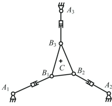
Figure 1: Schematics of a general 3-RPR planar parallel robot
2 Singularity Loci of 3-RPR Planar Parallel Robots
Referring to Fig. 1, we denote with Aiand Bithe base and
plat-form revolute joints, respectively. The directed distance between
Aiand Bialong the direction of prismatic actuator i is ρi, which
is the active joint variable. Finally, we denote by C the center of the mobile platform.
It is well known that the 3-RPR planar parallel robot is at a parallel singularity when the lines passing through the passive revolute joints in each leg intersect at one point or are paral-lel. These lines represent the reciprocal screws, i.e., the reaction forces applied to the mobile platform [17].
The singularity loci of this robot, defined as the set of posi-tions of point C where the robot is at singularity for a given ori-entation, were studied in detail in [18] and it was shown that they form a conic (i.e., a hyperbola, a parabola or an ellipse), unless there is an architectural singularity. An architectural singularity occurs, for example, when the mobile platform and the base form similar triangles, in which case there is an orientation at which all positions correspond to singularities. A more general study of the singularity surface of a 3-RPR parallel robot is given in [19]. In [17], it was shown that all points from this conic corre-spond to parallel singularities except for three (or two, or one) of them. These three points correspond to the poses of the plat-form in which one (or more) legs are in a serial singularity, i.e., in which two revolute joints in a leg coincide. Such a singularity corresponds to an uncontrollable passive motion [18]. In such a configuration, the reciprocal screw associated with the singular leg degenerates to two linearly independent forces. Thus, in such a configuration, there is a parallel singularity if and only if the lines associated with the two non-singular legs pass through the coinciding revolute joints of the singular leg. This would only be possible for special designs in which an angle of the base triangle is equal to the corresponding angle of the platform triangle.
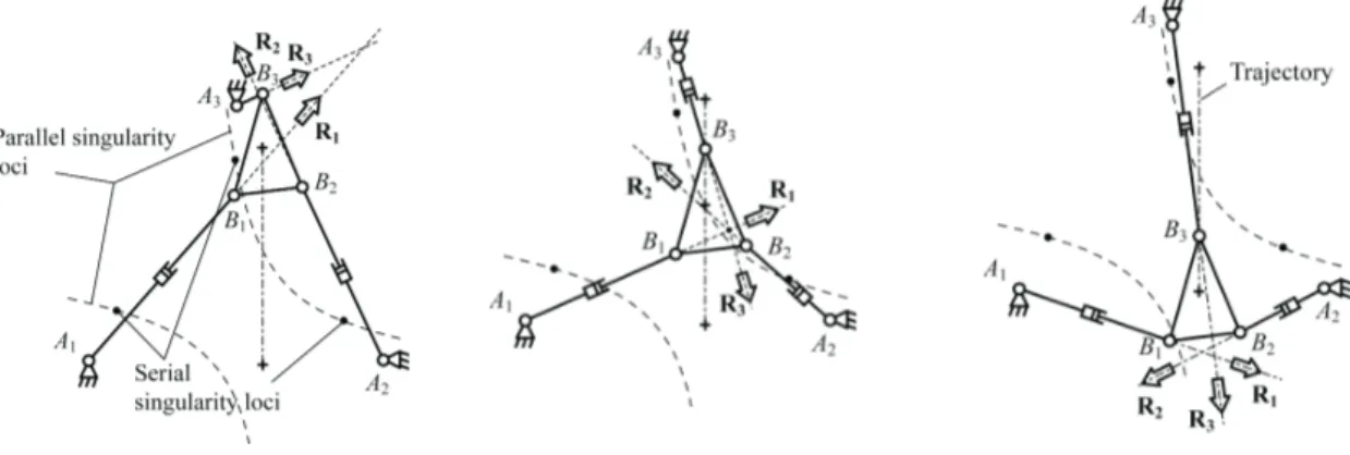
That passing the singularity curve means passing though a parallel singularity, as shown in Fig. 2, is fairly common knowl-edge. What no one has previously pointed out is that this larity curve has passages that usually correspond to serial singu-larities only. Figure 3 illustrates that virtually any general 3-RPR planar parallel robot can cross such a singularity curve through
these special passages, without even being near a parallel singu-larity (though measuring proximity to a parallel singusingu-larity is still an open question).
Since this robot can cross the singularity curves for any ori-entation without passing through a parallel singularity, it is obvi-ous that it can switch between any two assembly modes, without passing through a parallel singularity.
3 What Exactly is a Parallel Singularity?
Of course, the main purpose of this paper is purely theoretical. It is clear that, in practice, a 3-RPR parallel robot could hardly pass a serial singularity for many reasons. The most obvious one seems to be that a prismatic actuator that can change from posi-tive lengths to negaposi-tive ones can be difficult to build. However, this problem can be easily overcome if we use RRR legs instead, so this is not an issue. What is more difficult is to cope with the (uncontrollable) passive motion of the singular leg. If such a pas-sive motion occurs during a serial singularity, then the prescribed trajectory of Fig. 2 can no longer be followed. Finally, it would be even more difficult to drive the robot to such a configuration. Outside serial singularities, the 3-RPR parallel robot can accept input errors — this would simply result in output errors. How-ever, in a serial singularity, no errors are possible — this would result in jamming (the lengths of the two non-singular legs are not independent from one another). Note that this is not the case in most other parallel robots: they can cross a serial singularity without any difficulty.
This brings us to the essential question of what is a parallel singularity. The mobile platform clearly does not lose stiffness in the configuration in question. Yet, in this configuration, the num-ber of direct kinematic solutions abruptly drops to one (or two for some special cases). Indeed, the direct kinematic problem of this robot comes to finding the maximum six intersection points be-tween a sextic and a circle. When an actuator has zero length, this circle degenerates to a point, which explains the sudden drop in the number of solutions: there may be at most two “intersection points” between a point and a sextic.
This interpretation also helps understand why such a config-uration is not tolerant to input errors. In the case of non-zero leg lengths, if we slightly change the lengths of the two legs corre-sponding to the sextic, the latter will slightly change but there could still be six intersection points. If however, we do the same in the case of a zero-length leg, the point that is the degeneration of a circle, will no longer lie on the sextic.
4 Conclusions
This paper demonstrates that the problem of assembly-mode changing is still an open issue and its objectives should be bet-ter defined. Namely, the restrictions on such a change should be specified. Can we pass a serial singularity? If the answer is posi-tive, should we be able to do this in practice or not necessarily?
This paper also questions the very definition of a parallel sin-gularity, often associated with both a loss of stiffness and degen-eracy of the direct kinematics. An example of a serial singularity is given in which the direct kinematics degenerates but the mobile
platform does not lose stiffness. References
[1] Chablat, D., and Wenger, P., 2003, “Architecture optimiza-tion of a 3-DOF parallel mechanism for machining applica-tions, the Orthoglide,” IEEE Transactions on Robotics and
Automation, Vol. 19, No. 3, pp. 403–410.
[2] Arsenault, M., and Boudreau, R., 2004, “The synthesis of three-degree-of-freedom planar parallel mechanisms with revolute joints (3-RRR) for an optimal singularity free workspace” Journal of Robotic Systems, Vol. 21, No. 5, pp. 259–274.
[3] Li, H., and Gosselin, C.M., 2006, ”Determination of maxi-mal singularity-free zones in the workspace of planar three-degree-of-freedom parallel mechanisms” Mechanism and
Machine Theory, Vol. 41, No. 10, pp. 1157–1167.
[4] Li, H., and Gosselin, C.M., 2007, “Determination of maximal singularity-free zones in the six-dimensional workspace of the general Gough-Stewart platform,”
Mech-anism and Machine Theory, Vol. 42, No. 4, pp. 497–511.
[5] Merlet, J.-P., 1994, “Trajectory verification in the workspace for parallel manipulators,” International Journal
of Robotics Research, Vol. 13, No. 4, pp. 326–333.
[6] Dash, A.K., Chen, I.M., Yeo, S.H., and Yang, G., 2003, “Singularity-free path planning of parallel manipulators us-ing clusterus-ing algorithm and line geometry,” IEEE
Interna-tional Conference on Robotics and Automation, Taipei,
Tai-wan, September 14–19.
[7] Chablat D., and Wenger, P., 2001, “S´eparation des solu-tions aux mod`eles g´eom´etriques direct et inverse pour les manipulateurs pleinement parall`eles,” Mechanism and
Ma-chine Theory, Vol. 36, No. 6, pp. 763–783.
[8] Figielski, A., Bonev, I.A., and Bigras, P., 2007, “Towards development of a 2-DOF planar parallel robot with optimal workspace use,” IEEE International Conference on
Sys-tems, Man, and Cybernetics, Montreal, Quebec, Canada,
October 7–10.
[9] Mcaree, P.R., and Daniel, R.W., 1999, “An explanation of never-special assembly changing motions for 3-3 parallel manipulators,” International Journal of Robotics Research, Vol. 18, No. 6, pp. 556–574.
[10] Hunt, K.H., and Primrose, E.J.F., 1993, “Assembly config-urations of some in-parallel-actuated manipulators,”
Mech-anism and Machine Theory, Vol. 28, No. 1, pp. 31–42.
[11] Innocenti, C., and Parenti-Castelli, V., 1998, “Singularity-free evolution from one configuration to another in se-rial and fully-parallel manipulators,” Journal of Mechanical
Design, Vol. 120, No. 1, pp. 73–79.
[12] El Omri, J., and Wenger, P., 1995, “How to recognize simply a non-singular posture changing 3 DOF manipula-tor,” 7th International Conference on Advanced Robotics, pp. 215–222.
[13] Wenger, P., and Chablat, D., 1998, “Workspace and assembly-modes in fully parallel manipulators: A descrip-tive study,” Advances on Robot Kinematics, Kluwer Aca-demic Publishers, pp. 117–126.
[14] Zein, M., Wenger, P., and Chablat, D., 2008, “Non-singular assembly-mode changing motions for 3-RPR parallel ma-nipulators,” Mechanism and Machine Theory, Vol. 43, No. 4, pp. 391–524.
[15] Macho, E., Altuzarra, O., Pinto, C., and Hernandez, A., “Transitions between multiple solutions of the direct kine-matic problems,” Advances on Robot Kinekine-matics, Springer, 2008.
[16] Bamberger, H., Wolf, A., and Shoham, M., “Assembly mode changing in parallel mechanisms,” IEEE Transactions
on Robotics, in press, 2008.
[17] Bonev, I.A., Zlatanov, D., and Gosselin, C.M., 2003, “Sin-gularity analysis of 3-DOF planar parallel mechanisms via screw theory,” Journal of Mechanical Design, Vol. 125, No. 3, pp. 573–581.
[18] Sefrioui, J., and Gosselin, C.M., 1995, “On the quadratic nature of the singularity curves of planar three-degree-of-freedom parallel manipulators,” Mechanism and Machine
Theory, Vol. 30, No. 4, pp. 533–551.
[19] Husty, M.L., Hayes, M.J.D., Loibnegger, H., 1999, “The general singularity surface of planar three-legged plat-forms,” Advances in Multibody Systems and
Mechatron-ics, Gerhard-Mercator-Universit¨at, Duisburg, Germany,
Figure 2: Crossing the singularity curve generally means passing through a parallel singularity