UNIVERSITÉ DE SHERBROOKE
Faculté de génie
Département de génie mécanique
Système intégré de stockage de l’électricité
renouvelable par air comprimé
Integrated storage system for renewable electricity by
compressed air
Thèse de doctorat
Spécialité : Génie Mécanique
Mohamad Cheayb
January 2020
Sherbrooke, Québec, Canada
Jury members
Prof. Sébastien Poncet (Université de Sherbrooke)
Supervisor
Prof. Mohand Tazerout (IMT Atalantique), supervisor
Supervisor
Dr Mylène Marin Gallego (IMT Atalantique)
Co-supervisor
Prof. Hachimi Fellouah (Université de Sherbrooke)
Rapporteur
Prof. Yann Bartosiewicz (Université catholique de Louvain)
Examiner
Prof. Stéphane Hallé (École de Technologie Supérieure)
RÉSUMÉ
De nos jours, en raison des préoccupations liées à la protection de l'environnement et à la sécurité énergétique, l'utilisation des énergies renouvelables (ER) est en pleine croissance. L'intégration actuelle et future des ER entraîne des déséquilibres importants entre la production et la consommation d'électricité ainsi que des problèmes liés à la flexibilité et à la fiabilité de la gestion du réseau électrique. Dans ce contexte, les technologies de stockage de l'énergie électrique (SEE) s'avèrent être l'élément clé pour relever ces défis. En outre, dans les sites hors réseau qui ont recours aux moteurs diesel, les systèmes SEE sont essentiels pour accroître le taux de pénétration des énergies renouvelables et réduire la consommation d'énergie combustible.
De nouvelles évolutions dans le domaine du stockage d'énergie par air comprimé CAES (compressed air energy storage) ont été effectuées en utilisant la chaleur produite durant la phase de compression et en employant des réservoirs de stockage artificiels indépendamment de la disponibilité des cavernes souterraines. Grâce à ces améliorations, le CAES se révèle être une technologie prometteuse pour des applications pratiques. Récemment, le concept de stockage d'énergie trigénérative à air comprimé T-CAES (énergie thermique, mécanique et frigorifique) a été introduit. De nombreuses études soulignent la faisabilité et les avantages de ce système pour être implanté au niveau du consommateur.
Les objectifs de ce projet de recherche sont d'examiner les configurations du système T-CAES, de l'étudier par une approche couplée expériences/modélisations, ainsi que d’effectuer une optimisation technico-économique pour des systèmes à petite échelle, généralement inférieure à 500 kW.
En partant d'un modèle thermodynamique simplifié, les différentes configurations du système ont été étudiées et les paramètres clés ayant une influence dominante sur l'efficacité du système ont été identifiés. Cette analyse permet de mieux comprendre les principes fondamentaux et le concept thermodynamique de notre système, ainsi que de déduire deux configurations de base du système. Ensuite, un modèle thermodynamique détaillé de ces configurations a été développé incluant les aspects technologiques existants et les interrelations entre les composants.
Un banc expérimental a été utilisé pour valider le modèle des composants côté air et pour étudier l'effet des paramètres de fonctionnement sur l'efficacité du système. Les prédictions du modèle sont conformes aux mesures expérimentales pendant les phases de charge, de stockage et de décharge. De plus, il a été constaté que la chute de température à travers le régulateur de pression ne doit pas être ignorée et elle est régie par l'effet de Joule-Thomson. Par ailleurs, il a été observé que la température d'entrée du moteur pneumatique doit être étudiée pour évaluer de futures configurations.
L'étude se concentre ensuite sur l'étude des effets mutuels des paramètres de conception et de leur influence sur les performances du système, la densité énergétique et l'empreinte des échangeurs de chaleur via une étude paramétrique. Il est ressorti de cette analyse que la température du stockage d'énergie thermique, le nombre d'étages de compression et l'efficacité des échangeurs de chaleur devraient être choisis comme compromis entre l'efficacité du système, l'empreinte des échangeurs
de chaleur et le nombre requis d'étages de détente. Par contre, le choix de la pression maximale de stockage est un compromis à faire entre l'augmentation de la densité énergétique ou l'augmentation de l'efficacité du système. Une ligne directrice pour la conception optimale des paramètres clés mentionnés précédemment est ensuite fournie. Cette directive, la méthodologie et la procédure développée peuvent être étendues pour optimiser le système adiabatique A-CAES avec des changements mineurs. En se basant sur les technologies existantes et en utilisant une sélection optimale des paramètres, le rendement électrique de notre système à micro-échelle, généralement quelques kW, reste faible à 17%, tandis que l'efficacité du système augmente de 10.2% en ajoutant l'énergie électrique équivalente de production de froid et d'énergie thermique. Les faibles performances sont principalement liées aux pertes éxergétiques dans la vanne de détente et aux faibles rendements des machines à petites échelles.
L'étude a été complétée par l'élaboration d'un modèle économique du système en fonction de son échelle de puissance et d'énergie. Les résultats montrent que le coût des réservoirs de stockage d'air représente le coût le plus élevé et que la plage technico-économique optimale de la pression maximale de stockage se situe entre 120 et 200 bars. En outre, malgré les faibles performances du système, il a été constaté qu'il pourrait être compétitif à long terme avec les batteries électrochimiques en termes de coûts d'investissement, en particulier après avoir comptabilisé les coûts de production des énergies de chauffage et de refroidissement.
Les travaux futurs devraient être orientés vers l'amélioration de l'efficacité du système par l'étude du potentiel d'intégration des tubes à vortex et le développement technologique des machines de détente. De plus, les recherches futures peuvent envisager de réduire les coûts de stockage de l'air en intégrant les réservoirs sous pression en acier/béton qui sont en cours de développement. Mots-clés: Stockage par air comprimé, trigénération, étude expérimentale, modèle thermodynamique, optimisation technico-économique, étude paramétrique.
ABSTRACT
Nowadays, as a result of environmental and energy security concerns, the use of renewable energy (RE) is growing rapidly. The actual and prospective integration of RE results in significant imbalances between electricity production and consumption as well as problems related to the flexibility and reliability of grid operations. Here, electrical energy storage (EES) technologies turn out to be the key element to address these challenges. In addition, in off-grid sites relying originally on diesel engine, EES is a critical point in order to increase the penetration rate of RE and to reduce fuel energy consumption.
New advances in compressed air energy storage (CAES) have been made in the use of heat generated from compression and the use of artificial storage reservoirs independently from the availability of underground caverns. Such improvements make CAES a promising technology for practical applications. Recently, the concept of trigenerative compressed air energy storage T-CAES (heat energy, mechanical energy and cooling power) was introduced. Many studies highlight the feasibility and the benefits of this system to be placed close to the energy demand. The aims of this research project are to examine the T-CAES system configurations, to study it by a coupled experimental/modeling approach, as well as to conduct its techno-economic optimizations and economic feasibility at a small-scale, typically less than 500 kW.
Starting from a simplified thermodynamic model, the different configurations of the system was investigated and the key parameters having dominant influences on the system efficiency were identified. This analysis enhances the fundamental understanding and the thermodynamic concept of our system and enabled to conclude two main basic configurations. Then, a whole detailed thermodynamic model of the system configurations was developed including the existing technological aspects and the relations between components.
An experimental bench was used to validate the model of air side components and to investigate the effect of operating parameters on the system efficiency and the model accuracy.
Model predictions were consistent with experimental measurements during charge, storage and discharge phases. It has been found that the temperature drop across the pressure regulator should not be ignored and is governed by the Joule-Thomson effect. Besides, it has been observed that the input temperature of the air motor must be accounted for in the assessment of future improved configurations.
The study then focuses on investigating the mutual effects of the design parameters and their influences on the system performances, energy density and heat exchanger footprints via a parametric study. From this analysis, it is found that the temperature of the thermal energy storage, the number of compression stages and the effectiveness of heat exchangers should be selected as a trade-off between the system efficiencies, heat exchangers footprints and the required number of expansion stages. Meanwhile, the selection of the maximum storage pressure is a choice whether to increase the energy density or the system efficiencies. An optimal design guideline of the above key parameters is then provided. This guideline, the method and the procedure developed can be applied to the optimization of the trigenerative compressed air energy storage and could be
extended for the adiabatic one with minor changes. Based on existing technologies and using an optimal set of parameters, the round-trip electrical efficiency of our system at micro-scale, typically a few of kW remains low at 17%, while the system efficiency increases by 10.2% by adding the equivalent electric energy of cooling and heating energy productions. The poor performances are mainly linked to the exergy losses in the throttling valve and the low values of the component efficiencies at a micro-scale.
The study was extended by developing an economic model of the system as a function of its power and energy scale. The results show that the cost of air storage tanks accounts for the highest cost, and the optimal techno-economical range of the maximum storage pressure is [120 bars-200 bars]. Besides, regardless of the low efficiency of the system, it was found that it could be competitive with electrochemical batteries in terms of investments cost at long terms, especially when accounting for the free-cost of cooling and heating energy production.
Future work should focus on the improvement of the efficiency of the system by investigating the potential of integrating of vortex tube, and on technology development of expander machineries. In addition, future research can consider reducing the air storage cost by integrating the under-development steel/concrete pressure vessels.
Keywords: Compressed air energy storage, trigeneration, experimental study, thermodynamic model, techno-economic optimization, parametric study.
ACKNOWLEDGEMENTS
I would like to sincerely thank my supervisors Prof. Sébastien Poncet and Prof. Mohand Tazerout for providing me an opportunity to do this project. Thankfulness to Prof. Poncet, for his support, guidance, scientific vision and trust. My gratitude to Prof. Tazerout for his useful guidance, insight comments and his expertise. I am grateful to my co-supervisor Dr. Mylene Marin-Gallego for her valuable support, encouragement and understanding.
I would like to express my profound gratitude to the members of the jury, for their time to assess my work and their insightful suggestions and comments to improve it.
I would like to express my special thanks for our industrial partner Sigma Energy Storage, especially Dr. Richard Boudreault, not only for providing a part of the funding, but for his critical thinking and his professional cooperation.
Last, but not least, I owe my deep gratitude to the Conseil Régional d’Ile-de-France, for my previous Master Scholarship which allows me to enrich my education and my professional career.
Table of Contents
CHAPTER 1 - INTRODUCTION... 1
1.1 Background and motivation ... 1
1.2 Objectives and approach ... 4
1.3 Outlines ... 5
CHAPTER 2 – STATE OF ART ON ELECTRICAL ENERGY STORAGE TECHNOLOGIES 6 2.1 Overview on Electrical Energy Storage technologies... 6
2.1.1 Hydraulic Pumped Energy Storage... 6
2.1.2 Compressed Air Energy Storage ... 7
2.1.3 Thermal Energy Storage ... 8
2.1.4 Electrochemical batteries... 10
2.1.5 Chemical storage: Fuel cell ... 11
2.1.6 Other Storage Systems ... 12
2.2 Comparison and evaluation of EES technologies ... 12
2.2.1 Maturity ... 15
2.2.2 Power and energy scale ... 15
2.2.3 Efficiency ... 15
2.2.4 Energy and power density ... 15
2.2.5 Time of storage and self-discharge ... 16
2.2.6 Response time ... 16
2.2.7 Lifetime ... 16
2.2.8 Cost ... 17
2.2.9 Environmental impacts ... 17
2.2.10 Global synthesis on EES ... 17
2.3 General working principle and classifications of CAES technologies ... 18
2.3.1 Working principle ... 18
2.3.2 Classifications ... 19
2.4 Conventional/Diabatic compressed air energy storage D-CAES ... 22
2.5 Adiabatic compressed air energy storage A-CAES ... 23
2.5.1 A-CAES at high TES temperature ... 24
2.5.2 A-CAES at medium TES temperature ... 25
2.6 Trigenerative Compressed Air Energy Storage T-CAES ... 29
2.6.1 Evaluation of the performances of T-CAES ... 35
2.6.2 Optimization studies on Adiabatic and T-CAES. ... 37
2.7 Conclusions and Problematic ... 38
CHAPTER 3 - THERMODYNAMIC CONCEPT AND ENERGETIC ANALYSIS OF THE TRIGENERATIVE COMPRESSED AIR ENERGY STORAGE ... 40
3.1 Objectives and originality ... 40
3.2 Methodology ... 40
3.3 Governing thermodynamic equations ... 41
3.3.1 Charging phase ... 41
3.3.2 Discharging phase ... 43
3.3.3 Global system assessment ... 44
3.4 Thermodynamic concept ... 45
3.4.1 Adiabatic concept... 45
3.4.2 Trigenerative concept ... 47
3.5 Trigenerative Compressed Air Energy Storage possible configurations ... 49
3.5.1 Energy analysis method ... 49
3.5.2 Possible configurations ... 50
3.5.3 Basic configurations ... 52
3.6 Conclusion ... 53
CHAPTER 4 – DESCRIPTION AND MODELLING OF THE TRIGENERATIVE COMPRESSED AIR ENERGY STORAGE. ... 55
4.1 Objectives ... 55
4.2 System description ... 55
4.3 Modeling of the T-CAES process ... 58
4.3.1 Modeling assumptions ... 58
4.3.2 Modelling of the charge phase ... 59
4.3.3 Modelling of the discharge phase ... 62
4.3.4 Modelling of heat exchangers and thermal energy storage ... 68
4.4 Evaluation criteria ... 73
4.5 Conclusion ... 74
CHAPTER 5 - EXPERIMENTAL TESTS AND MODEL VALIDATION OF A SMALL SCALE TRIGENERATIVE COMPRESSED AIR ENERGY STORAGE SYSTEM ... 76
5.1 . Objectives and originality ... 76
5.2 Experimental Setup ... 76
5.2.1 . General description ... 76
5.2.2 . Compressor chain... 78
5.2.3 . Storage reservoir ... 79
5.2.4 . Air motor and pressure regulator ... 79
5.3 . Experimental results and model validation... 80
5.3.1 . Charge phase ... 81
5.3.2 . Storage phase ... 84
5.3.3 . Discharge phase ... 84
5.4 Experimental Focus on the throttling valve and the air motor ... 87
5.4.1 . Throttling valve ... 87
5.4.2 . Air Motor ... 87
5.5 . Conclusions and perspectives ... 88
CHAPTER 6 - PARAMETRIC OPTIMIZATION OF SMALL SCALE TRIGENERATIVE COMPRESSED AIR ENERGY STORAGE ... 91
6.1 Objectives and originality ... 91
6.2 Methodology of the parametric optimization ... 91
6.3 . Results and discussions ... 93
6.3.1 . Effects of the temperature of the thermal energy storage... 93
6.3.2 . Effects of the number of compression stages ... 95
6.3.3 . Effect of the effectiveness of intercooling HEX ... 97
6.3.4 . Effect of the effectiveness of discharge phase HEX ... 99
6.3.5 . Effect of the maximum storage pressure ... 101
6.3.6 . Effect of the cooling energy ... 104
6.4 . Characteristics of the micro-scale T-CAES... 104
6.5 . Conclusions and perspectives ... 106
CHAPTER 7 - TECHNO ECONOMIC STUDY OF T-CAES ... 109
7.1 . Introduction... 109
7.2 . Economic Modeling of the components of the T-CAES ... 110
7.2.1 . General Method... 110
7.2.2 . Application of the method on T-CAES plant. ... 112
7.3.1 . Methodology ... 115
7.3.2 . Model reliability... 117
7.4 . Results and discussions ... 118
7.4.1 . Optimal storage pressure range ... 118
7.4.2 . Cost of the components and the plant ... 119
7.4.3 . Comparison of the T-CAES with batteries ... 123
7.5 Conclusions and Perspectives ... 125
CHAPTER 8 – CONCLUSIONS AND PRESPECTIVES... 126
8.1 Conclusions (en français)... 126
LIST OF TABLES
Table 2.1: Thermo-physical proprieties of sensible heat TES materials (synthetized from [27,28] and
[29])... 9
Table 2.2: Thermo-physical proprieties of PCM for TES (collected from [28] and [30]). ... 10
Table 2.3: Comparison of the evaluation criteria of EES technologies (collected from [2,4]). ... 13
Table 2.4: Characteristics of the Huntorf and McIntosh power plants [9,10]. ... 23
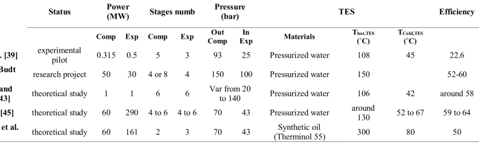
Table 2.5: Main characteristics of LT-A-CAES as proposed by relevant research studies ... 30
Table 2.6: Operation parameters of air side components of T-CAES as proposed by related authors. .... 34
Table 2.7: Characteristics of TES components of T-CAES as proposed by the mentioned authors. ... 35
Table 2.8: Performances achieved by the studies conducted on T-CAES ... 36
Table 3.1: Numerical example of an ideal A-CAES. ... 46
Table 3.2: Imposed parameters to study the T-CAES. ... 47
Table 3.3: Numerical values of energy flows of an ideal T-CAES. ... 50
Table 3.4: Numerical values of energy streams of the first basic configuration... 53
Table 5.1: Experimental characteristics of compression chain. ... 79
Table 5.2: Experimental characteristics of the discharge phase ... 80
Table 5.3: Experimental and model results of the charge phase. ... 81
Table 5.4: Experimental and model results of the discharge phase. ... 85
Table 5.5: Power and pressure output of the air motor for different operating conditions. ... 88
Table 6.1: Fixed parameters and variable parameters of the parametric study. ... 92
Table 6.2: Optimal solution of the design parameters. ... 104
Table 6.3: Energy outputs, efficiencies and total HEX footprints of the two configurations with and without enabling the cooling energy. ... 104
Table 6.4: Output parameters of the charge phase for the first configuration. ... 105
Table 6.5: Output parameters of the discharge phase for the first configuration. ... 106
Table 6.6: Main output parameters of the model for the first configuration. ... 106
Table 7.1: Coefficients required for the calculation of capital cost of mechanical components (base year 2001 for compressors and HEX [6]). ... 114
Table 7.2: Comparison between the results of the cost model and cost data of Matches Company. ... 118
LIST OF FIGURES
Figure 1.1: The main applications of electrical energy storage (EES). ... 2
Figure 1.2: Distribution of isolated sites (left [9]) and wind farms in Canada (right, taken from Canadian Wind Energy Atlas). ... 3
Figure 2.1: Schematic of pumped hydroelectric storage plant [2]. ... 6
Figure 2.2: Representative diagram of compressed air storage systems [2]. ... 7
Figure 2.3: Scheme of the application of TES in the power plant “Solar Power Tres”[26]. ... 8
Figure 2.4: General schematic of operation of electrochemical batteries [2]. ... 11
Figure 2.5: Classifications of compressed air energy storage systems [31]. ... 19
Figure 2.6: Representative scheme of isobaric CAES concept (a) [32] and the Hydrostor demonstration project (b) [33]. ... 21
Figure 2.7: Process operation of combined isobaric-CAES and PHS system proposed by Kim et al. [32]. ... 22
Figure 2.8: Basic concept of A-CAES [31]. ... 23
Figure 2.9: Schematic diagram of A-CAES at high TES temperature [31],[42]. ... 25
Figure 2.10: Block diagram of A-CAES at medium TES temperature [31]. ... 26
Figure 2.11: Schematic of A-CAES at low temperature of TES [31]. ... 26
Figure 2.12: Detailed schematic diagram of the experimental pilot “TIC-500”, Chinese Academy of Sciences [39]. ... 27
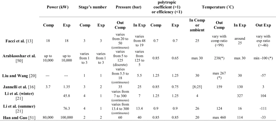
Figure 2.13: T-CAES without preheating as proposed by Facci et al.[13], Lv et al.[19], Liu and Wang [20]and Arabkoohsar et al.[50]. ... 31
Figure 2.14: T-CAES with preheating as proposed by Jannelli et al.[16], Li et al. [21] and Han and Guo [51]. ... 32
Figure 3.1: Scheme of the charging phase. ... 41
Figure 3.2: Scheme of the discharging phase. ... 42
Figure 3.3: Block diagram of the thermodynamic equations of the T-CAES... 45
Figure 3.4: A-CAES representation on the Clapeyron diagram. ... 47
Figure 3.5: Input and Output temperature variation (left figure) and energy distribution as a function of the heat recuperated to stored ratio. ... 48
Figure 3.6: Electrical efficiency variation as a function of the heat recuperated to stored ratio. ... 48
Figure 3.7: Resolution algorithm to derive the possible configurations of the T-CAES. ... 50
Figure 3.8: Discharging phase of the three configurations of the T-CAES. ... 52
Figure 3.9: General basic configurations deduced for T-CAES. ... 54
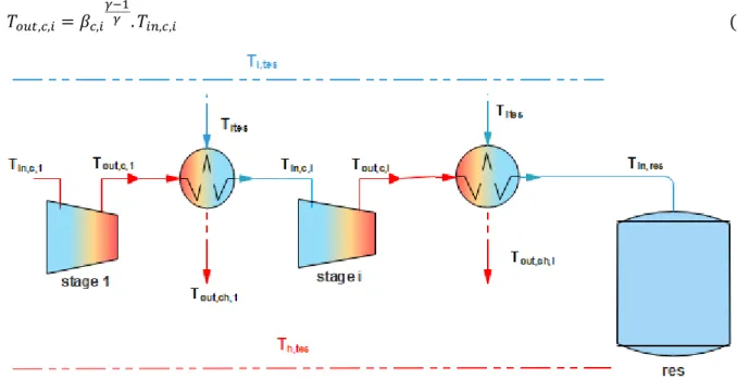
Figure 4.1: Schematic diagram of the proposed trigenerative compressed air energy system with the notations. ... 57
Figure 4.2: Schematic diagram of the last expansion stage subsystem (the air motor AM) and temperature levels of streams for the first configuration (a) and the second configuration (b). ... 58
Figure 4.3: Block diagram of the model of air side of the charge and storage phase. ... 63
Figure 4.4: Algorithm developed to select the optimal number of expansion stages. ... 66
Figure 4.5: Block diagram of the model for the air side of discharge phase. ... 68
Figure 4.6. variation of temperature of air and water flow versus heat duty for the first configuration (a) and second configuration (b). ... 69
Figure 4.7: Block diagram of the thermodynamic model of the whole T-CAES system with main input parameters (black) and output parameters (red). ... 75
Figure 5.1: Photograph of the CAES pilot unit at IMT Atlantique, France. ... 77
Figure 5.3: Representative scheme of the intercooled air compressor. ... 78
Figure 5.4: Pressure variations during the charge phase (lines represent the model and points for experimental). ... 82
Figure 5.5: Input and output temperatures of each component during the charge phase (lines represent the model and points for experimental). ... 83
Figure 5.6: Air mass flow and compressor power during the charge phase (lines represent the model and points for experimental). ... 83
Figure 5.7: Pressure and temperature of the stored air during the storage phase. ... 84
Figure 5.8: Pressure variations during the discharge phase (lines represent the model and points for experimental). ... 86
Figure 5.9: Input and output temperatures of each component during the discharge phase(lines represent the model and points for experimental).. ... 86
Figure 5.10: Isenthalpic curves of throttling in the pressure regulator (lines represent the model and points for experimental). ... 87
Figure 5.11: Power versus RPM of the air motor (left) and thermodynamic to electrical conversion (right) (lines represent the model and points the experimental). ... 89
Figure 6.1: Effect of the thermal energy storage temperature... 95
Figure 6.2: Effect of the number of compression stages. ... 97
Figure 6.3: Effect of the effectiveness of intercooling HEX. ... 99
Figure 6.4: Effect of the effectiveness of discharging HEX. ... 101
Figure 6.5: Effect of the maximum storage pressure. ... 103
Figure 6.6: Comprehensive efficiency (left axis) and energy density (right axis) at constant maximum to minimum pressure ratio as a function of the maximum storage pressure (the variation of the minimum storage pressure is shown in the secondary x-axis on the top) ... 103
Figure 7.1: Variation of cost pressure factor of tank versus maximum storage pressure (fixing the tank diameter at 0.21 m). ... 113
Figure 7.2: Values and interpolated function of the cost of micro-turbines versus shaft power. ... 114
Figure 7.3: Algorithm of finding the expansion mass flowrate for an imposed power output. ... 116
Figure 7.4: Variation of reservoir number as a function of maximum storage pressure (output energy of 30 kWh)... 119
Figure 7.5: Variation of reservoir costs and electric efficiency as a function of maximum storage pressure (output energy of 30 kWh)... 119
Figure 7.6: Variation of reservoir costs as a function of maximum storage pressure and output energy. ... 119
Figure 7.7: Variation of the output power and the cost of each component as a function of the output energy with a discharge to charge ratio of 0.21. ... 120
Figure 7.8: The cost of caverns in large scale CAES (y axis is the y-axis is either cost/£106 or cost per unit/£ (kWh) [11]. ... 121
Figure 7.9: Variation of the output power and the cost of each component as a function of the output energy with a discharge to charge ratio of 0.75 . ... 122
Figure 7.10: Variation of the total costs of the plant as a function of the output energy. ... 123
Figure 7.11: Capital cost of Pb-Acid batteries against typical capacity (on logarithmic scale) as reported by companies(black) and according to industry standards (blue). ... 123
Figure 7.12: Capital cost of lead acid battery and T-CAES against electric energy output, without considering the heating energy(left) and with taking the equivalent electric energy of this latter (right). ... 124
Figure 7.13: Capital cost of lead acid battery and T-CAES against electric energy output, with a power range higher than 30 kW. ... 125
NOMENCLATURE
T Temperature (˚C) P Pressure (bar) ∆Pl Pressure losses (bar)
Cp Heat capacity (kJ.kg-1.˚C-1)
μT Joule Thomson coefficient (°C/bar)
Nc Number of compression stages Ne Number of turbines
n Polytropic coefficient βc Compression ratio
βAM Expansion ratio of air motor
βe Expansion ratio of turbine Ẇ Power (kW)
ṁ Mass flow rate (kg.s-1)
ε Heat exchanger effectiveness ms Stored mass (kg)
δ Maximum to minimum pressure ratio V Volume (m³)
t Time (s)
Nres Number of air storage tanks
Nu Nusselt number
Ra Rayleigh number
h Heat convection coefficient (W.m-2.K-1)
H Height (m) d Thickness (m)
D Internal diameter (m)
Rth Thermal resistance (W-1.m.K)
λ Thermal conductivity (W.m-1.K-1)
Qr Thermal energy recuperated used on preheating of the compressed air (kWh)
Qcool Cooling energy (kWh)
Qheat Heating energy (kWh) Qs Thermal energy stored (kWh)
Crs Heat recuperated to heat stored ratio
UA Heat exchanger footprint (W.K-1)
Ed Energy density (kWh.m-3)
COP Coefficient of performance Ƞ Efficiency
Ƞg Comprehensive efficiency
Pinch Pinch point temperature difference I.CH.S Initial charging state
I.DIS.S Initial discharge state
α Time of discharge to time of charge ratio
NOMENCLATURE
CA0 Cost at base conditions (USD)
Fp Bare module factor of operating pressure
FM Bare module factor of Materials
Iyi Cost index
ABBREVIATIONS
EES Electrical Energy Storage PHS Pumped Hydraulic Storage CAES Compressed Air Energy Storage C-CAES Conventional CAES
A-CAES Adiabatic CAES T-CAES Trigererative CAES TES Thermal Energy Storage AM Compressed Air Motor HEX Heat exchanger
SUBSCRIPTS
c compression
e expansion
i Compression stage or heat exchanger number i j Expansion stage or heat exchanger number j
out output in input amb Ambient d Expansion valve el electrical m mechanical th thermodynamic
th,m Thermodynamic to mechanical conversion tt Total to total
ts Total to static
s isentropic
0 stagnation
rem remaining
cold,TES Cold thermal energy storage h,TES Hot thermal energy storage
ch charge
dis discharge
SUBSCRIPTS
w water
res reservoir
max Maximum pressure min Minimum pressure
A Component capacity such as power, volume or surface
1
CHAPTER 1 - INTRODUCTION
1.1 Background and motivation
The demand for electrical energy continues to grow and is projected to increase by 56% between 2010 and 2040 per person [1]. This increase is mainly met by thermal and nuclear power plants [2,3]. The most frequent problems arising from fossil fuels are mainly:
- Economic: they are exhaustible sources and their prices are in rise. - Environmental: they are the main cause of greenhouse gas emissions.
Nowadays, with the concerns about the environment and energy security, the use of renewable energies (RE) is becoming increasingly important [4] and the electricity market is experiencing major changes by integrating these resources. In this context, many countries policies purpose is to encourage RE investments by utilities implement policies such as feed-in tariffs, carbon taxes and/or renewable portfolio standards [5].
On the other hand, Increased penetration of renewable energies leads to significant imbalances between instantaneous electricity production and consumption. Therefore, Electrical energy storage (EES) is becoming a vital aspect to meet these challenges [2,3,4]. The fundamental idea of EES is to recover excess energy supply over demand, store it and deliver it during the period of insufficient energy production.
Primarily, EES is used to supply high peaks in demand that exceed the production capacity of power plants [3,6]. This prevents the installation of an additional power plant, which is better than oversizing the power plants and operating it at part-load with low performance far from the design conditions. Now, Electrical Energy Storage (EES) plays a key role in integrating renewable energy sources [2,4]. Besides, EES systems ensure the flexibility and reliability of grid operations especially smart grids [7].
Referring to Wolf [3], Chen et al. [4] and Ibrahim [6], the application of EES (Figure 1) takes place at several levels as follows:
Generation: normally on a large or medium scale, energy is stored during the off-peak period (night) for use in the peak period (day).
Consumption: the reduction of the peak load can also be achieved at the consumer level. In addition, in order to reduce consumer dependence on the electricity grid, renewable energies can be integrated into their own facilities. Hence, EES serves to manage power flows.
Off-Grid Sites: they are communities that are not connected to national electricity transmission grids. In most of these communities, power is provided by diesel generators. With the integration of renewable energies, EES is necessary to increase the penetration rate of renewable energies, or even to pursue energy self-sufficiency.
2
Figure 1.1: The main applications of electrical energy storage (EES).
Concerning Off-Grid sites, the number of populations living in isolated communities or who use unreliable networks is estimated at 1.2 billion people worldwide [8] (a number comparable to the population of China). In Canada, there are approximately 292 remote communities, including 44 in Quebec, with a total population of 194,281, including 34,729 in Quebec [9].
The connection of these communities to public electricity grids results in significant power losses, so local production is a necessity. The diesel engine is the most popular solution in Quebec. The total installed capacity in all these communities is estimated at 128 MW, of which 107 MW is diesel-powered. In addition to the disadvantages of using fossil fuels, a second challenge resides in the high costs of transporting diesel fuel to remote locations [6].
On the other hand, most sites in Canada have significant wind potential given their near-shore or mountainous locations (see Figure 1.2). Similarly, in the world, the majority of islands (such as the Greek or Canary Islands) [10,11] also have significant wind resources. Moreover, the populations located in Africa, South Asia and East Asia benefit from a very large solar resource (this population represents 95% of the 1.2 billion people disconnected through the main electricity grids) [8]. Consequently, the integration of renewable energies appears a very interesting solution.
3
Figure 1.2: Distribution of isolated sites (left [9]) and wind farms in Canada (right, taken from Canadian Wind Energy Atlas).
Once the renewable energy production is incorporated with the initial production provided by diesel engine, this latter will function at partial loads which means at low efficiency. Adding to that, it should operate above 30% of its nominal power in order to ensure a proper lubrication [6,12]. As a result, these conditions force to reject a significant percentage of the electrical energy produced (unloaded energy) and prevent a high penetration of renewable, solar or wind energy [6,12,13].
Another challenge that leads to the difficult market penetration of wind/diesel production systems is the dynamic variations in wind speed. The diesel engine is started for safety reasons even if the wind production is higher than 10% -15% of the load [6,14] which leads to the increase in start/stop cycles and consequently cause wears of engine parts, and increases its maintenance cost.
In order to overcome these problems, EES becomes a key solution to increase the penetration rate and the profitability of renewable energy integration, and to recover the unloaded energy. Several EES such as pumped hydroelectric (PHS), compressed air energy storage (CAES), thermal energy storage (TES), chemical or electrochemical batteries, flywheel, capacitor and supercapacitor have been developed so far. Each system has certain advantages and limitations based on different criteria such as efficiency, energy density, power range, time of response and investment cost [2]. Among EES technologies, compressed air energy storage CAES is considered a very promising technology. At a large scale on the level of producer, it is a strong alternative to the pumped hydroelectric when nearby mountains are not available [2,4] while underground reservoirs such as saline dome caverns, porous rock formation or old mines are accessible [12,15]. Meanwhile, at smaller scales on the level of consumer, CAES attracted recently more attention in favor of the possibility of using overground pressure vessel reservoirs [13,16] and their potential applications especially for off-grid sites [1,6,15].
Until now, only two commercial Compressed Air Energy Storage (CAES) installations have been operated. They have been built to minimize the fuel consumption in conventional gas turbine cycles during high demand periods [1,12,17]. In fact, in this simple concept of CAES called diabatic (D-CAES), the heat produced during the compression phase is wasted leading to moderate
4
efficiencies (42%-54%) [12]. Recently, this technology regained attention with a major improvement, namely the use of the heat from the compression process in the expansion phase. This second generation recognized as adiabatic compressed air energy storage (A-CAES) could be competitive with others EES [18], thanks to its high availability and starting reliability, environmentally benign, long life, low operation and maintenance costs [12,18,19].
Previously, it has been demonstrated that CAES is adaptable to produce supplementary heating and cooling energy which improves further its round trip efficiency [13,20,21]. Hence the trigenerative compressed air energy storage CAES has been introduced. In other words, the T-CAES is based on using the compression heat directly as a heating energy or as a preheating energy in the expansion phase to increase the electrical efficiency. Furthermore, the production of cooling is possible because of the partial use of the compression heat.
The development of small scale T-CAES to be placed close to energy demand (off-grid sites or at the consumer level) is of great interest [13], given the technical ease of transfer of thermal and chilling energy at short distances. However, limited number of studies has been conducted on this system and they mostly focused on demonstrating its concept and its adaptability to specific applications.
1.2 Objectives and approach
The aim of this research project is to study this new generation of compressed air storage technology at small scales. The present work is besides part of a joined research project undergoing in IMT Atlantique (France) and Université de Sherbrooke (Canada) dedicated to the implementation of small-scale T-CAES close to energy demand or in off-grid sites especially in remote communities in the North of Québec.
The main objective of this project is the analysis of the T-CAES from a theoretical and experimental perspectives and the techno-economic optimization of the system to propose an efficient design guideline.
The general objective includes the following specific objectives:
Conducting a thermodynamic and energetic analysis of the system in order to gain a better understanding of the process and deduce its possible configurations.
Developing a detailed thermodynamic model of each component which leads to elaborate a global model to predict its performances.
Performing experimental tests to validate the simulation model as well as to investigate its operation and thermal behaviors.
Carrying out a thermodynamic optimisation via parametric study, including economic criteria, with investigating the mutual effects of design parameters.
Developing an economical model to estimate the capital cost of the system as well as to compare it with its alternative electrical energy storage system.
5
1.3 Outlines
The thesis is divided on six chapters:
Chapter 2 presents a literature review on different technologies of electrical energy storage and interprets its evaluation criteria. The particular emphasis will be placed on compressed air energy storage, its principles and system configurations, its modeling and analysis methods aspect as well as past achievements and results of previous related studies. This helps to locate the gabs on our research field and to elaborate the clear methodology essential to examine the T-CAES.
Each of the following chapters includes each of the objectives presented above with a detailed explication of the work methodology.
Chapter 3 presents the fundamental principle of the T-CAES system based on the first law of thermodynamic. In line with this, a simplified thermodynamic model is developed in order to deduce the different possible configurations of the T-CAES and to identify the key elements that influence the system performances.
Then, in Chapter 4 a detailed thermodynamic model of the plant is developed with taking into account the technological aspects and technical constraints of each component.
In Chapter 5 the industrial experimental pilot unit implemented in GEPEA laboratory at the IMT Atlantique, France is described. Afterward, the model developed in chapter 3 for air-side components is validated experimentally by paying a careful attention to each component.
Chapter 6 focuses on the assessment of the effect of the most relevant design parameters on the system performance and operation via a parametric study. Along with this, the effect of each design parameter on the others as well as economic considerations are investigated. As a conclusion, an optimal design guideline is provided.
In Chapter 7 an economical model of the system is developed and an optimal techno-economic design solution is deduced. Then, the cost of the system as a function of its power scale is discussed and compared to batteries.
6
CHAPTER 2 – STATE OF ART ON ELECTRICAL ENERGY
STORAGE TECHNOLOGIES
As mentioned in the last chapter, Electrical Energy Storage (EES) is becoming a vital aspect to ensure the balance between energy production and demand [2,4,22,23] and to deal with the intermittent nature of solar or wind energy sources. Moreover, in off-grid sites, EES appears as a key component to achieve a sufficient penetration of renewable energy resources [10,15]. Electrical Energy Storage technologies are declined into 4 categories: mechanical energy, electrochemical energy, thermal energy and chemical energy.
This chapter is composed of 2 main parts:
- In the first part, the principle of the various storage systems and their evaluation criteria are briefly presented in order to draw an overall conclusion on the position of compressed air storage in relation to other EES.
- In the second part: compressed air storage technologies will be described in depth, paying attention to the various studies recently published on this subject.
2.1 Overview on Electrical Energy Storage technologies
2.1.1 Hydraulic Pumped Energy Storage
Hydraulic pumped energy storage (PHS) is based on storing the electrical energy in the form of gravitational energy. As shown in Figure 2.1, it includes 2 reservoirs at different elevations (higher and lower reservoir). When excess electricity is produced, the water from the lower reservoir is pumped to the upper one. As needed, water is turned back on a turbine to produce electrical power.
Figure 2.1: Schematic of pumped hydroelectric storage plant [2].
PHS is the most widely deployed technology at large scales with high efficiency of 85%.
Nevertheless, it requires considerable investments, a specific geographical context mainly mountain areas, and a long time of construction [4].
7
The installed capacity of hydropower station achieved 1267 GW in the world by the end of 2017, which represents 16.4% of the total renewable energy production [24]. As for the application of this technology in EES, it represents 94 % of global electricity storage by capacity with a value of 153 GW [24].
The contribution of PH in electricity production is 11 % in France, while it is 62% in Canada [25]. In Québec, this contribution is very high which achieves 97% [25]. However, isolated sites still rely on diesel engine as the main electricity producer.
2.1.2 Compressed Air Energy Storage
In addition to PHS, Compressed Air Energy Storage (CAES) is implemented at large scale which can provide a capacity over 100 MW. It involves mainly two generations:
1 The conventional CAES (C-CAES) which is a mature and commercialized technology. 2 The under-development system recognized as Advanced Adiabatic compressed air energy
storage (AA-CAES) or simply adiabatic (A-CAES), and the recently introduced system called Trigenerative-CAES (T-CAES).
Figure 2.2 presents a general diagram describing different CAES principles. C-CAES stands on the basis of the gas turbine cycle with the difference that the compression and expansion phases are time-delayed. The thermodynamic process in a conventional CAES may be described as follows: during the period of excess energy production, ambient air is compressed via a multi-stage compressor with intercooling. The associated compression heat is lost to the environment. Compressed air is stored in underground reservoirs (in the case of large scale) or in overground tanks (for small scale). During the period of high energy demand, the mechanical energy is converted again into electrical energy by expansion. Stored air is released, heated by means of combustion before expanding into the gas turbine to generate electricity.
The aim of the A-CAES concept is to recuperate the lost heat and use it in the expansion stages. A detailed description of this generation and the trigenerative concept will be presented in the next parts of this chapter.
8
CAES is mainly applied to large-scale applications (tens or hundreds of MW). Recently, for small scale applications, by using overground pressure vessel reservoir. CAES is considered as a very promising alternative solution for energy storage in remote areas [6], and especially small scale Trigenerative-CAES (T-CAES) to replace diesel power stations used by small housing groups.
2.1.3 Thermal Energy Storage
Thermal Energy Storage (TES) consists in storing energy by cooling, heating, melting, or vaporizing a material [6]. This energy will be available once the process is reversed [2,6]. TES is used in a wide range of applications, mainly for heating and cooling in buildings as well as for electricity production.
Heat sources come either directly from renewable energy (solar energy or from electricity by means of electrical resistance [4,6]) or from unavoidable heat resulting from industries (gas-fired power plants, incineration plants, processes) [6]. The stored thermal energy is converted into electrical form by the use of classical engine cycles. As an application of TES, Figure 2.3 shows the scheme of Solar Tres power plant, Spain. the solar heat is stored by molten salt materials, then the heat is used to produce the superheated steam needed in the Rankine cycle to produce the electric energy.
The storage materials are selected according to the temperature level of the process and material properties such as: thermal inertia, heat capacity and mass density. The storage materials can be classified according to (1) sensible heat storage or (2) latent heat storage material.
Figure 2.3: Scheme of the application of TES in the power plant “Solar Power Tres”[26].
Sensible heat storage materials
The common materials used are presented as follows:
1. Solid media: these include underground rocks (Borehole Thermal Energy Storage) and natural aquifers (Aquifer Thermal Energy Storage) for large scale applications, and surface
9
tanks containing solid materials such as concrete [4] or ceramic [3] for small-scales applications. It is important to note that underground rocks and aquifers are intended for daily (day/night) or seasonal (summer/winter) storage at intermediate temperature levels (<80ºC) [4].
2. Liquid media: the commonly used materials are thermal oils and pressurized water. On the other hand, there is a growing interest in molten salt and ionic liquids, more specifically Room Temperature Ionic Liquids RITL [4]. These latter are characterized by a freezing point below 25ºC without risk of decomposition at high temperatures [4].
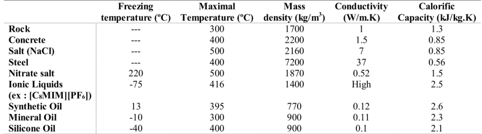
Table 2.1 presents a comparison of the thermo-physical properties of the most common TES materials.
Table 2.1: Thermo-physical proprieties of sensible heat TES materials (synthetized from [27,28] and [29]).
Freezing
temperature (ºC) Temperature (ºC) Maximal density (kg/mMass 3) Conductivity (W/m.K) Capacity (kJ/kg.K) Calorific
Rock --- 300 1700 1 1.3 Concrete --- 400 2200 1.5 0.85 Salt (NaCl) --- 500 2160 7 0.85 Steel --- 400 7200 37 0.56 Nitrate salt 220 500 1870 0.52 1.5 Ionic Liquids (ex : [C8MIM][PF6]) -75 416 1400 High 2.5 Synthetic Oil 13 395 770 0.12 2.6 Mineral Oil -10 300 900 0.11 2.3 Silicone Oil -40 400 900 0.1 2.1
It is obvious that for temperatures below 100ºC, water is still the best choice due to its high calorific capacity and thermal conductivity and its very low cost.
For high temperature values, nitrate salt (molten salt) and thermal oils are the most commonly used [27,28,30]. The main drawback of nitrate salt is its high freezing temperature (even above room temperature). Besides, thermal oil has low thermal conductivity and mass density values.
Ionic liquids have an interesting thermal property and can be used for low and high temperatures of storage. Although, they have not yet been used in practical applications [28].
Latent heat storage materials
Phase change materials (PCMs) offer valuable benefits since they store energy at a well-defined temperature and perform a high energy density. In counterpart, they require a heat transfer fluid cycle to transmit the thermal energy [4],which increases the system cost. There are several PCM materials such as paraffin, organics or inorganics materials as well as eutectic mixtures. Table 2.2 lists some used or potentially applicable PCMs materials for relatively low or medium temperatures (less than 200˚C).
10
Table 2.2: Thermo-physical proprieties of PCM for TES (collected from [28] and [30]).
Materials Melting
temperature
Latent heat Thermal conductivity (˚C) (kJ/kg) (W/m.K) Organic Erythritol 118 89.9 --- Trans-1,4-polybutadien 145 144 --- Paraffin C22-C33 67 189 --- Paraffin Waxes 64 173.6 --- Inorganic MgCl2.6H2O 117 168.6 --- Mg (NO3)2.2H2O 130 275 --- Inorganic eutectic 48%Ca (NO3)2-25%KNO3
-7%NaNO3
140 0.519
KNO3—NaNO2—NaNO3 142 84 0.6
40% KNO3-60%NaNO3
(Molten Salt) 222
inorganic eutectic + Lithium LiNO3 + NaNO2 + NaNO3 + KNO2
+KNO3
95.7 100<𝐿𝑣<300 or above 300 KNO3 + LiNO3 + NaNO3 117 100<𝐿𝑣<<300
or above 300
The materials are characterized by their latent heat, melting temperature levels and thermal conductivity. The latent heat is relatively high but the low values of thermal conductivity is a challenge to overcome and has been the focus of ongoing research projects [28]. It should be noted that the addition of lithium to molten salts lowers their melting points, which allow their use as phase change materials (see the last three lines of Table 2.2). This makes these products more and more popular [28].
2.1.4 Electrochemical batteries
The electrochemical storage is based on the transformation of the chemical energy to electrical energy (during the discharge phase) which results from electrochemical reactions and vice versa (during the charge phase). A wide variety of batteries have been used, while the most common are: Lead-acid and Lithium-ion batteries.
As shown in Figure 2.4, batterie contains two electrodes (anode and cathode) with an electrolyte which promotes the movement of ions between these electrodes. During the discharge phase, the electrons move from the anodes to the cathodes in the external circuit, while the electrochemical reaction occurs at the two electrodes. The reaction is reserved in the charging phase. In order to illustrate the battery functioning, the chemical reactions of Lead acid battery are presented as follow:
11
Reaction at the Anode (negative plate): 𝑃𝑏+ 𝐻𝑆𝑂4−𝑑𝑖𝑠𝑐ℎ𝑎𝑟𝑔𝑖𝑛𝑔 → 𝑐ℎ𝑎𝑟𝑔𝑖𝑛𝑔 ←
← 𝑃𝑏𝑆𝑂4+ 𝐻++ 2𝑒−
Reaction at the cathode (positive plate): 𝑃𝑏𝑂2+ 𝐻𝑆𝑂4−+ 3𝐻++ 2𝑒− 𝑑𝑖𝑠𝑐ℎ𝑎𝑟𝑔𝑖𝑛𝑔 → 𝑐ℎ𝑎𝑟𝑔𝑖𝑛𝑔 ←
← 𝑃𝑏𝑆𝑂4+ 2𝐻2𝑂
Figure 2.4: General schematic of operation of electrochemical batteries [2].
Electrochemical batteries are rather mature and very well established for building or small communities’ applications. Their attractiveness is driven by their high roundtrip efficiency (60%-90%), their flexibility and high responsiveness (short response time), thereby enhancing the stability of electricity networks.
On the other hand, batteries have a short lifetime and a low energy density (which explains their applications in installations of several kW [6]). In addition, most batteries contain toxic materials. Batteries covers several types: lead-acid, nickel-cadmium, sodium-sulfur and lithium-ion batteries [4].
2.1.5 Chemical storage: Fuel cell
As its name indicates, the electricity storage is powered by the use of a fuel and an oxidant. The basic principle is as follows: the discharge phase consists of consuming a fuel A (e.g. 𝐻2) to produce electricity and a chemical product B (e. g. 𝐻2𝑂). Chemical A is regenerated by consuming electricity while B acts as a reagent (during the charging phase) as follow:
𝐶ℎ𝑎𝑟𝑔𝑖𝑛𝑔 𝑝ℎ𝑎𝑠𝑒: 𝐵 + 𝐸𝑛𝑒𝑟𝑔𝑦 → A 𝐸𝑥: 2𝐻2𝑂 + 𝐸𝑛𝑒𝑟𝑔𝑦 → 2 𝐻2+ 𝑂2 𝐷𝑖𝑠𝑐ℎ𝑎𝑟𝑔𝑖𝑛𝑔 𝑝ℎ𝑎𝑠𝑒: 𝐴 → 𝐵 + 𝐸𝑛𝑒𝑟𝑔𝑦 𝐸𝑥: 2 𝐻2+ 𝑂2 → 2 𝐻2𝑂 + 𝐸𝑛𝑒𝑟𝑔𝑦
12
Fuels encompass using dihydrogen, hydrocarbons, alcohols and even some metals [4]. Dioxygen is not the only oxidant, chlorine and chlorine dioxide can also be used [4]. However, the focus has been on hydrogen fuel cells in which the electrical energy is stored by the electrolysis of water [3,6]. These cells provide intrinsic advantages such as scalability and high energy density [2,4]. Regardless of these advantages, this technology has a low efficiency and remains expensive at the moment [4].
2.1.6 Other Storage Systems
It is intended here to be of the short storage time solutions (a few minutes or hours) such as the superconductor and the flywheel storage systems. Flywheel accumulators include a flywheel associated with a motor-generator. In this way, energy is stored in the form of kinetic energy. While the energy in superconducting Magnetic Energy Storage (SMES) is stored in the form of a magnetic field in favor of the almost zero electrical resistance of the superconducting coils. Besides, the inductor is maintained in a superconducting state by a liquid helium magnetic conductor.
2.2 Comparison and evaluation of EES technologies
The ideal EES solution applicable to every energy context does not exist. Rather, the choice of the suitable technology depends on the application requirements on one hand, and the characteristics of each EES technologies on the other hand. In this part, the evaluation criteria of EES are defined and presented in Tables 2.3 and 2.4. Then, for each criterion a comparison between these technologies is carried out in order to highlight the usefulness of the CAES technology and existing data relevant to small-scale CAES.
13
Table 2.3: Comparison of the evaluation criteria of EES technologies (collected from [2,4]).
Efficiency (%) Power (MW) Energy density
(kWh/m³) Maturity
PHS 70-85 100-5000 0.5-1.5 Mature
High Large scale
Underground CAES 42,54 110-290 3-6 Commercialized
Moderate Large scale
Underground A-CAES 70 expected Tens or hundreds of MW Similar to CAES Under development
Medium-Large scale
Aboveground-CAES Not evaluated 0 -3 Higher than underground
CAES Under development Small scale High
TES 30-60 0-300 80-500 Under development/early
commercialized Relatively low Small or high scale Medium
Electrochemical
batteries Depends on battery 60-90 type
0-0.3; 0-40
Depends on battery type (200-400 for some types) 50-80 Commercialized High Small or medium scale With a low or medium
power density
Some types are under development
Hydrogen fuel cell 20-50 0-50 500-3000 Under development
/demonstration projects Relatively low Small to medium scale High
Flywheel 90-95 0-0.25 20-80 Early commercialized
Very high Small scale With high power density
SMES 95-97 0.1-10 0.2-2.5 Demonstration/under
development Very high Small-medium scale With high power density
14
Table 2.3 (continued): Comparison of the evaluation criteria of EES technologies.
Time of response Storage duration Life time (years) Cost ($/kWh) Specific Cost ($/kWh per cycle)
PHS Minutes Hours-Month 40-60 5-100 0.1-1.4
Not fast Long term Medium
Underground CAES Minutes Hours-Month 20-40 2-50 2-4
Medium Long term Low
Underground A-CAES Minutes Hours-Month 20-40
Medium Long term
Aboveground-CAES Seconds-Minutes Hours-Month More than 23 200-250 8-10
Long term
TES Minutes-Days
(Months for HT-TES) 10-30 3-30 2-4
Electrochemical batteries Milliseconds Minutes-Days
(Month for some types) 5-15 (300-500 for some types) 100-400 (8-20 for some types) 20-100 Fast Short and medium terms
(long for some types)
Hydrogen fuel cell Seconds Hours-Month 5-15 High
Fast
Flywheel Seconds Seconds-Minutes 15-20 250-350 3-25
Fast Short term
SMES Milliseconds Minutes-hours More than 20 200-300
15
2.2.1 Maturity
Maturity indicates the level of commercialization which exhibits technological barriers, technical reliability, economic profitability as well as research and development needs. EES can be classified into 3 categories:
1. Mature technologies: Hydraulically pumped energy storage (PHS), C-CAES and lead-acid batteries are widely recognized and commercialized [4].
2. Developed technologies: Conventional CAES, flux batteries, SMES, TES and flywheel are technically developed and available on the market, but they are not yet widespread because they require further improvements to be more cost-effective and reliable [4].
3. Under development technologies: It includes fuel cells, A-CAES and the trigenerative CAES system targeted in this study.
2.2.2 Power and energy scale
This criterion is defined by the capacity generation of the system in terms of power and energy and reflects the size of the components of the storage system.
Referring to Table 2.3, PHS and CAES are the most suitable for large-scale applications (>100 MW). Some types of electrochemical batteries on its development stage (such as flux batteries), fuel cells, TES and CAES systems are compatible with medium-scale applications (5-100 MW). Conventional electrochemical batteries, fuel cells and recently the trigenerative CAES system studied in this thesis are adaptable for small-scale applications (<5 MW).
2.2.3 Efficiency
It is the ratio of the output energy produced to the input absorbed energy. The overall efficiency is governed by energy losses and the conversion efficiency of energy forms during charging and discharging phases (e.g. the conversion efficiency of electrical energy into mechanical energy). Generally speaking, the efficiency at design condition is often provided in the literature without taking into account partial loads operations [9].
PHS and electrochemical batteries accounts for the highest efficiency (71%-85% for PHS and 60-90% for batteries). CAES (even for A-CAES) have lower efficiency with a maximum expected value of 70%, while CAES technology maintains a high value of efficiency at partial load operations as reported by Luo and Wang [17]. TES and hydrogen storage have the lowest efficiency values (<60%).
Finally, it is important to notice from Table 2.3 that the efficiency of CAES at small scales has not been confirmed and reported in the literature.
2.2.4 Energy and power density
Energy density is defined by the available energy stored per unit mass or volume, while the power density represents the ratio of the delivered power per unit mass or volume. These two terms should not be confused, energy density reveals the volume or mass required to satisfy energy needs, a higher value means a more compact system. This is particularly sought for on-board applications [9], which can also lead to a lower cost. Nevertheless, a higher energy density does not mean a
16
higher power density and vice-versa. This later gives further an idea on how the stored energy can be released.
As it can be seen from Table 2.3, PHS and CAES are characterized by a low energy density so that they require large natural reservoirs and they are designed for stationary applications at large scales. As for TES, it shows a medium energy and power densities. The power density here has no importance because it is in line with the energy density.
Electrochemical batteries have moderate energy density, which explains their on-board applications. Although, the power density does not achieve high values expect for lithium-ion batteries. These latter are considered as a very promising technology for transport applications, especially the heavy ones. Flywheel and SMES have moderate and low energy density respectively. By contrast, their power density is very high which explains their relevance for high power appliances with short discharge time.
With regards to small scale CAES, it is characterized by high energy density since the air is stored at high pressure in artificial tanks which overcomes the need of natural reservoirs. However, the value of the density has not been rigorously accounted.
2.2.5 Time of storage and self-discharge
The self-discharge is defined by the ratio of the energy dissipated to the energy stored during a given storage period. The possible time of storage is basically driven by the self-discharge [2,4, 6]. The energy is lost according to the process type via heat transfer, electrochemical losses, or air leaks emphasizing that this energy does not include the conversion energy losses as it the case in accounting the efficiency.
Compressed air, pumped hydraulic and dihydrogen can be stored for long periods of time (up to seasons) compared to other technologies.
2.2.6 Response time
This criterion is defined by the time required to generate the required power. Flywheel, SMES and batteries have relatively short response times (<1 second) compared to other technologies, making them attractive for usage for the stability of electrical networks [3, 4]. But, CAES and PHS have moderate response time.
2.2.7 Lifetime
The lifetime is quantified by the cyclic longevity of the storage system or in another term the number of charge-discharge cycles it can undergo before its performances degrades. It is related to fatigue, wear and tear or deterioration of system components. It is expressed by the number of years, or more rigorously by the number of cycles. Beyond this number of cycles, the system becomes unable to meet the needs or the costs associated with the maintenance increase, for example, after a certain number of years, electrochemical batteries cannot deliver the same level of energy for which they were designed and its capacity degrade.
Thermal and mechanical storage systems (TES, PHS, Flywheel and CAES) have a long lifespan, which could extend to 60 years. On the contrary, chemical and electrochemical storages suffer
17
from low lifetime. For instance, conventional batteries (lead-acid batteries) last on average 5 years or less due to chemical or electrochemical degradation.
2.2.8 Cost
The cost encompasses the investment, the maintenance and the operation costs. It is expressed per kWh of output energy. However, it is more appropriate to accounts for the lifetime when the cost is calculated so that it is often expressed as cost/kWh/cycle. The cost is very important in technology selection for the manufacturer [3], as well as for the consumer [9]. Industrial producers adopt cost-competitive technology, meanwhile user does not invest in a solution which does not provide economical profitability.
The cost values presented in Table 2.3 account for the capital cost and do not include maintenance, operating and installation costs. CAES, PHS and TES systems are the most cost-effective in terms of costs per kWh and per kWh per cycle. On the other hand, Electrochemical batteries are low-cost technologies for the short term (in terms of $/kWh) but they have a limited lifetime, which makes them expensive and uneconomical for the long term (in terms of $/kWh/cycle).
As a first evaluation of small-scale CAES, it appears to be costly in the short term, nonetheless the cost per cycle seems to be interesting and sufficiently higher than that of batteries. Note that the cost values presented in Table 2.3 are not based on detailed study of the system.
2.2.9 Environmental impacts
Despite the fact that energy storage promotes the integration of renewable energy, some technologies still have negative impacts on the environment. As an illustration, conventional CAES involves fuel combustion and the majority of electrochemical batteries contain toxic substances that may remain for long time. On the contrary, the new generations of CAES, TES and flywheel are environmentally friendly.
2.2.10 Global synthesis on EES
Energy storage techniques are very wide. There is no single optimum technology that can combine high efficiency, cost-effectiveness, longevity or all the other criteria mentioned above. The suitable technology depends mainly on its application.
Generally speaking, EES has not been reached technical maturity expect for lead-acid batteries, PHS and conventional CAES. Indeed, research and development has been very active in recent years especially for batteries, fuel cells and CAES.
At large scale, PHS is the most widely implemented. It is technically mature with good efficiency (70-85%), long storage time and high lifetime. Besides, compressed air energy storage (CAES) has a strong potential especially after ongoing research to improve its efficien cy by introducing the adiabatic-CAES concept. At small scale, electrochemical batteries remain the most commonly used technology. However, they have been suffering from low lifetime and they entail using toxic materials and chemical wastes that remain for a long time.
Currently, there is an emphasis on small-scale air compression storage. The major attractions lie in the ability to store air in artificial tanks that can be installed at any site, and in the possibility to
![Figure 2.3: Scheme of the application of TES in the power plant “Solar Power Tres”[26]](https://thumb-eu.123doks.com/thumbv2/123doknet/3383656.97984/26.918.163.729.654.926/figure-scheme-application-power-plant-solar-power-tres.webp)