Science Arts & Métiers (SAM)
is an open access repository that collects the work of Arts et Métiers Institute of
Technology researchers and makes it freely available over the web where possible.
This is an author-deposited version published in:
https://sam.ensam.eu
Handle ID: .
http://hdl.handle.net/10985/13061
To cite this version :
Tristan RÉGNIER, Guillaume FROMENTIN, Bertrand MARCON, José OUTEIRO, Alain
D'ACUNTO, Arnaud CROLET, Timothée GRUNDER - Fundamental study of exit burr formation
mechanisms during orthogonal cutting of AlSi aluminium alloy - Journal of Materials Processing
Technology - Vol. 257, p.112-122 - 2018
Any correspondence concerning this service should be sent to the repository
Fundamental study of exit burr formation mechanisms during orthogonal
cutting of AlSi aluminium alloy
Tristan Régnier
a,c,⁎, Guillaume Fromentin
a, Bertrand Marcon
a, José Outeiro
a, Alain D
’Acunto
b,
Arnaud Crolet
c, Timothée Grunder
caLaBoMaP– Arts et Métiers Paristech Cluny, Rue porte de Paris, 71250 Cluny, France bLEM3– Arts et Métiers Paristech Metz, 7 rue Félix Savart, 57073 Metz, France cLinamar– Montupet, 3 rue de Nogent, 60290 Laigneville, France
A R T I C L E I N F O
Keywords:
Burr formation mechanisms Orthogonal cutting Aluminium alloy
A B S T R A C T
Burr formation during machining is an important issue in industry. It causes an additional deburring operation, which is time consuming and has a negative economic impact.
This study aims to analyse burr formation mechanisms and its accumulation in successive passes during orthogonal cutting of a cast aluminium alloy. A customized experimental setup was developed, which includes a high speed imaging system and a laser profilometer. A design of experiments using the setup mentioned pre-viously is carried out and a methodology for geometric burr characterization is developed and applied. Furthermore, statistical representation of the obtained results is performed, which allows the understanding of the geometric heterogeneity influence associated to burr formation mechanisms and to work material micro-structure.
Based on the exit burr analysis, new geometrical criteria are proposed for the characterisation and the de-finition of two main burr formation mechanisms.
The influence of cutting parameters on burr morphology along the workpiece exit edge is investigated in depth. The results show that two types of burrs can be produced simultaneously along the workpiece exit edge due to the work material microstructure heterogeneity. The results present as well the influence of low uncut chip thickness that leads to a higher proportion of burrs without chamfer. This type of burr is higher and more propice to burr accumulation. After performing several cutting passes, these burrs may be eliminated and re-placed by a burr with chamfer.
1. Introduction
Burr formation occurs during each machining operation. In several cases, deburring is required to avoid any physical injuries or premature wear of a mechanical system due to any burr release. Because deburring operations are considerably time-consuming and hence, expensive, many companies try to reduce burr formation during machining.
Due to its geometric complexity and the number of different burr morphologies, several burr dimension definitions exist. TheISO 13715 (2000)proposes a measure of burr height from the theoretical exit edge of the workpiece to the top of the burr. To understand burr formation,
Schafer (1975) describes a burr using five geometrical parameters, presented inFig. 1, but the measurements of the burr root thickness, the burr root radius and the burr thickness are difficult to perform
non-destructively.
Referring to burr formation in general,Gillespie and Blotter (1976), showed that four burr formation mechanisms exist. They are: Poisson burr, rollover burr, tear burr and cut-off burr. These different burr formations are described inFig. 2. The Poisson burr is caused by the plastic deformation of the workpiece around the tool, during its entry, by Poisson effect. The rollover burr results from a burr accumulation along the exit edge of the workpiece. The tear burr is due to the tearing produced by the chip separation from the workpiece. The cut-off burr appears only during the cut-off of the workpiece.
According toHashimura et al. (1999a)different burrs are produced with respect to workpiece material. During the cut of a ductile material, the burr formed is similar to a rollover burr and is called “positive burr”. As for a brittle material, a fractured surface is generated due to a
crack propagation along a“negative shear zone” and is called “negative burr” byIwata et al. (1982). These two terms are now generic. How-ever, further studies by Nakayama and Arai (1987) showed that the fracture depends not only on the toughness of the workpiece material but also on uncut chip thickness, rake angle and cutting speed.
Combining the burr formation behaviour observed in situ by SEM (Scanning Electron Microscopy) with the material mechanical proper-ties,Ko and Dornfeld (1991)proposed an analytical model describing the burr initiation, its development and its formation. The model results fit well the experimental ones for positive burr formation. As for ne-gative burr modelling, no studies have been carried out for now.
The mechanical properties of the workpiece material seem to have a considerable influence on burr morphology. Hypoeutectic cast alumi-nium alloys have a dendritic microstructure. The main parameters to characterise these alloys mechanical properties are the SDAS (Secondary Dendrite Arms Spacing) and the Fe-rich intermetallic compounds and Si particles size and shape.Wang (2003)analysed the fracture behaviour of cast aluminium alloys during tensile tests. He discovered that under a SDAS size of 30μm, the fracture is inter-granular. It occurs along grain boundaries, going from a Si-particle to another. On the contrary, above a SDAS size of 50μm, the mechanism is more transgranular. The fracture occurs along cell boundaries.
Gillespie (1973)had studied burr formation for several con figura-tions such as slot milling or shoulder milling. The author analysed each new edge created by the cut and its associated burr; he gave mechanical explanations for burr’s shape relying to two burr formation mechan-isms: the rollover burr and the so-called entrance burr which is actually a Poisson burr.
The axial depth of cut has a significant impact on burr height as well
as on burr morphology for milling operations. Olvera and Barrow (1995)investigated the effect of such parameters on burr height during
milling of a carbon steel. They highlighted a transition axial depth of cut at which burr height decreases considerably. The burrs produced prior to this transition depth of cut are long and thin and are called primary burrs. Upon this transition, short and thick burrs are formed, known as secondary burrs.Chern (2006)studied the burr formation of three different aluminium alloys during face milling. He highlighted 5 types of burrs, i.e. knife type burrs (due to plastic bending of uncut material near the transition machined surface), curl-type burrs (rollover of a positive burr), wave-type burrs (which takes its name from its periodic distribution, linked with the feed per tooth), edge breakout (negative burr) and secondary burrs (one of the threefirst type of burrs, fractured due to a high deformation). For each burr type, an explana-tion of the formaexplana-tion behaviour is given. The author also showed that the transition axial depth of cut value depends mainly on workpiece material and in-plane exit angle.
Regarding burr height prediction during milling, Bourlet et al. (2016)propose a phenomenological model based on a design of ex-periments approach on a cast aluminium alloy. During this study, using polycrystalline diamond tools, several parameters have been varied such as the angle between the machined and exit surfaces of the workpiece (wedge angle), the depth of cut, or the exit angle of the tool, defined in this article as the angle between the exit surface of the workpiece and the normal of the rake face when the insert exits the worpiece (before, the exit surface of the workpiece in itself was the reference). The angle between the normal of the workpiece exit surface and the normal of the insert rake face defines it. The study leads the authors to conclude that the interaction between the uncut chip thickness when the insert exits the workpiece and the exit angle in-fluences mainly burr height. They compared the correlation between the design of experiments results and the exit order sequence of the inserts, defined inFig. 3. This criteria, introduced byHashimura et al. (1999b), is thought to influence greatly the burr height. The
compar-ison does not allow to conclude that the exit order sequence is the only parameter influencing burr height.
A phenomenon emphasizedfirstly byNakayama and Arai (1987)is the burr accumulation in successive cutting passes. Burr accumulation is the capacity of a burr to increase its height after each tool pass, creating a rollover burr. It occurs only during positive burr formation, and supposedly when the uncut chip thickness used in the next tool pass is lower than the burr root thickness of the burr previously formed. This phenomenon has been observed on burrs produced laterally compared Fig. 1. Parameters defining a burr (adapted fromSchafer (1975)).
to the cutting edge (lateral or sideward burrs) during orthogonal cut-ting. This sideward burr accumulation is for instance the cause of high lateral burr height during shoulder milling. Likewise, during their stu-dies on burr behaviour of face milling on stainless steels,Da Silva et al. (2015a)showed that if no deburring operation is carried out between two passes, milling burr height increases. On the contrary, deburring between each pass leads to a repeatable burr height.
Several studies have been performed on burr formation analysis. However, different aspects, such as the influence of the microstructure and burr formation mechanisms, have not been explored yet or can be deeply analysed with the help of new measuring techniques. Hence, this study aims to analyse exit burrs morphologies during orthogonal cut-ting, using micrographs and SEM observations, of a cast aluminium alloy. It also proposes better criteria helping to qualify accurately the burrs geometries. The variability of these criteria values along the sample thickness as well as the effect of uncut chip thickness on burr formation are also investigated. Finally, burr accumulation at the exit edge of the workpiece and general exit burr formation mechanisms analyses are exposed.
2. Experimental procedure and work material 2.1. Experimental setup
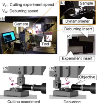
The orthogonal cutting tests are conducted in a 3 axis CNC machine DMG DMC85V equipped with linear motors. The X axis of the machine provides the cutting velocity, set to 120 m/min. To analyse the burr formation, a high-speed CCD camera (PHOTRON SA-Z), shown in
Fig. 4a, is used. For this study, the camera records the end of the cut
with a frame rate of 30,000 fps. Magnification is performed by a ×10 Mitutoyo objective together with lens tubes to reach an observation window of 1.835 × 1.835 mm², presented in Fig. 4e. To record the cutting forces during machining, a piezo-electric dynamometer Kistler model 9119 AA2 is used and visible inFig. 4b.
Before starting the tests on a new sample, a pass is performed to make the machined surface parallel to the cutting direction. To remove the burr generated during this operation on the exit edge of the workpiece, a deburring cut is performed with a second insert set on the opposite direction of thefirst insert used to generate burrs, as shown in
Fig. 4c. After each cutting pass, another pass in opposite direction is also performed with this deburring insert in order to remove the burr, as represented in Fig. 4d and e. As for the burr accumulation in-vestigation, the burr removal pass is omitted. The height difference between both cutting edges is measured regularly to update the offset of both landmarks, ensuring an accurate uncut chip thickness.
For each cutting condition, 3 repetitive passes are performed, each preceded by a deburring pass, as previously explained. The last pass is then followed by two additional passes without deburring, to study the burr accumulation. The burr accumulation study has been avoided for the highest uncut chip thickness (i.e. h = 150μm) because the camera would be needed to be adjusted after each pass, due to the deep affected zone.
All six tools were tested under the same conditions, using the tests protocol detailed inFig. 5, corresponding to 198 tests in total.
2.2. Burr topography measurement
Burr measurement is performed using an in-situ laser profilometer (Keyence LJ-V7060) with an optimised measurement repeatability of 0.4μm along the normal direction and 5 μm along the longitudinal di-rection. The laser is mounted on the Z axis carriage after each pass and a scan is performed by moving the Y axis of the CNC machine, as shown inFig. 6a. Each incremental encoder pulse of the linear axis triggers a laser pulse and in return a profile is generated. The gap between two laser pulses is 8μm while the data interval along the laser line reaches 20μm. The scanning setup is presented inFig. 6b–d. An animation presenting the whole procedure is available here.
The results of each scan performed along the approximately 4 mm samples thickness are then reduced to a 3 mm centred set of data points to exclude the edge effect.
Fig. 3. Exit order sequences of an insert during milling (from Kumar and Dornfeld (2003)).
2.3. Work material and cutting conditions
Six different uncoated tungsten carbide (WC-Co) inserts are used. To avoid lateral burr formation during the tests and lateral deburring, a 2° inclination angle is set for each insert. The cutting tools (geometrical and material) properties and the cutting parameters are listed in
Table 1.
It has to be noted that not only a positive rake angle is used, but also some null and negative ones. These two last geometries are used to reproduce the rake angles usually found in milling cutters for ma-chining aluminium alloys using PCD (Polycrystalline diamond) tools. The studied work material is a cast aluminium alloy ENAC-AlSi7Mg0.3 + 0.5Cu (ENAC-AlSi7Mg0.3 standardised inNF EN1706 (2010), with 0.5% Cu added) heat treated T7, with the chemical composition described inTable 2.
The work material properties are listed below inTable 3.
3. New characterisation criteria and in situ measurement method Before starting the result analysis, new criteria will be proposed to improve the geometrical description of two burr types presented by
Iwata et al. (1982)and more specifically the burr formed after a crack propagation (also known as negative burr until now), as shown in
Fig. 7. A new in situ burr measurement is also proposed.
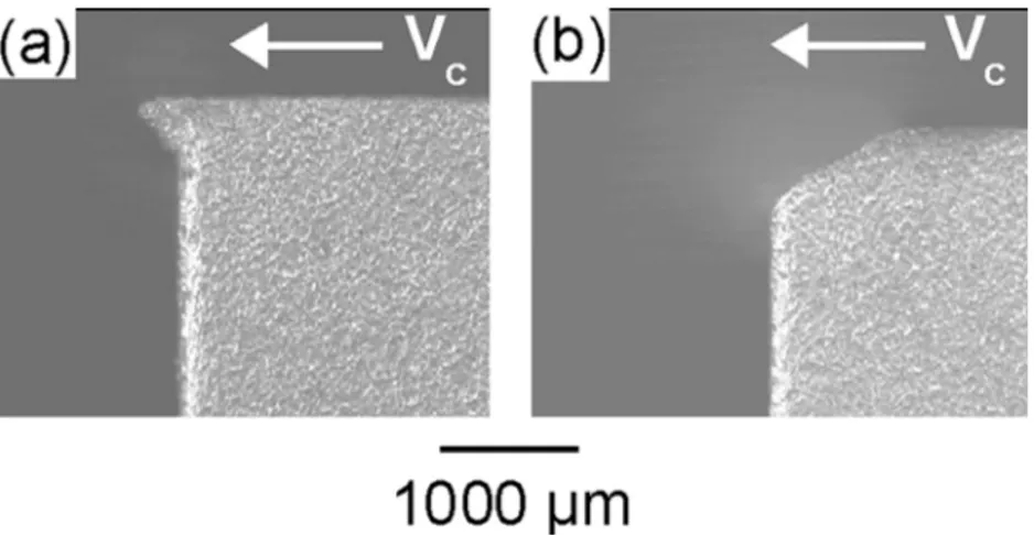
Due to the fact that a burr is defined by the standard as a “rough remainder of material outside the ideal geometrical shape of an external edge”, only the material beyond the theoretical edge is considered as a burr. That is the reason that burrs will be discussed as those with or without chamfer and not as positive or negative burr in this study.
To characterise a burr, the main parameter used is the burr height. There are nevertheless other parameters such as burr thickness or burr root radius that can characterise a burr, as discussed in Section 1.
However, such parameters cannot be used for a complete study along the exit edge of the workpiece as they imply destructive methods for the measurement.
For the burr without chamfer, it is better to analyse the burr height (Bh), the burr root radius (Brr), both defined previously from earlier
studies, and the burr length (Bl), described inFig. 8. The burr height is
used to describe the distance between the tip of a burr and the exit surface of the workpiece. The burr root radius helps to classify burrs by their robustness. The increase of the radius indicates a higher burr strength. This parameter is easier to measure compared to burr thick-ness because the thickthick-ness may vary along the burr profile. Finally, the burr length, being a new proposed parameter, helps to classify burrs after accumulation. This type of burr is driven by a rollover mechanism. This mechanism denotes that after several passes, burr height stops increasing while burr length may still increase, as explained byRégnier et al. (2016).
As for burrs with chamfer, several parameters are suggested to de-scribe more efficiently this type of burr. TheFig. 9shows the para-meters used to describe or quantify a burr with chamfer.
The burr height (Bh) is recommended as it helps to differentiate the
two types of burr. Burrs with chamfer generally have a relatively lower height than burrs without chamfer. According to Toropov and Ko (2006), the shape of the fracture surface is curved. The corner radius (Cr) could be used to identify this curvature, which may be linked to the
elastic spring back at the end of the cut. However, this radius is rela-tively high and the curved shape may not be obvious in certain cases (Fig. 7b for example). The shape of the fracture surface could be then considered as plane, so as to compare with the corner of the workpiece and a chamfer. This assumption allows us to define a new parameter, the chamfer angle (Γc), which is linked to the fracture surface
or-ientation which appears at the end of the cut. The chamfer height (Ch)
is defined as the distance along the cutting direction between the in-itiation of the fracture and its end, before the formation of burr. The chamfer depth (Cd) is, as it is named, the depth of the chamfer from the
beginning of the chamfer to the intersection between the chamfer and the exit surface. Those two last parameters help to define the formation of chamfer and the origin of the burr formation. Finally, a burr root radius can also be measured.
In this study, burr root radii as well as burr length have not been fully measured along the sample thickness because of the necessity of using destructive methods for the measurement. However, certain measurements of the burr length could be performed on samples images obtained by high-speed camera.
Fig. 6. Burr scanning setup.
Table 1
Tool properties and cutting conditions.
Parameters Values
Tool material WC-Co
Cutting speed, Vc(m/min) 120
Uncut chip thickness, h (mm) 0.02; 0.03; 0.04; 0.05; 0.07; 0.1 and 0.15 Width of cut, b (mm) 4
Rake angle,γ (°) −10; 0 and 10 Clearance angle,α (°) 10
Edge radius, rβ(μm) 10 and 20
Table 2
Chemical composition of an AlSi7Mg0.3 + 0.5 Cu alloy.
Si Fe Cu Mn Mg Zn Ti Others
6.5–7.5 < 0.19 ≈ 0.5 < 0.1 0.25–0.45 < 0.07 0.08 to 0.25 0.1
Table 3
Material properties of AlSi7Mg0.3 + 0.5 Cu– T7 according to Linamar – Montupet company.
Property Value
Work material AlSi7Mg0.3 + 0.5Cu– T7
Density (g/cm3) 2.66
Young Modulus (GPa) 78.5 [74.2 ; 82.6] Elongation at break (%) 2.1 [0.9 ; 3.9] Tensile Yield strength (MPa) 250.3 [243.9 ; 257.2] Tensile Maximum strength (MPa) 295.6 [276.5 ; 317.1]
4. Experimental results and analysis
The following subtopics will present the results obtained during the experiments carried out in orthogonal cutting in planing configuration. An analysis of burrs morphologies along the sample using high speed camera frames, micrographs and SEM analyses is given. Then the re-sults of repetitive tests on burrs formation as well as those of the in-fluence of uncut chip thickness are discussed. Finally burr accumulation in successive passes is investigated. All the tendencies described in this section are quite repeatable with reference to the cutting tool geometry (rake angle and cutting edge radius), as can be attested by the graphics disposed in supplementary material 1 until 5.
4.1. Burr morphologies
It is discovered that most of the tests performed generate both burr types (i.e. burr with and without chamfer) along the same exit edge of the workpiece. As seen inFig. 10, the proportion between each burr type is not constant and their position varies depending on the cutting condition. This denotes a heterogeneous nature of the work material.
Currently, studies were dealing with average values of burr height. However, the difference of burr height between both types is quite high. Since both burr types may appear in a same sample during one single cut, a new way of result representation is used. As the burr height data are dispatched into two Gaussians distributions (one for burr with chamfer and another for burr without chamfer), the average value or the boxplot representations are not relevant. Another type of statistical plot, developed by Hintze and Nelson (1998), called violin plot, is presented later, for example inFig. 17. This type of representation is suitable to show burr height, hence such plot is used in this study.
Burr with chamfer formation is presented inFig. 11. The video frames, available here, show that, asIwata et al. (1982)have observed, Fig. 7. Burr called positive burr (without chamfer) (a) and burr called negative burr (with chamfer) (b).
Fig. 8. Burr without chamfer and its geometrical descriptors.
Fig. 9. Burr with chamfer and its geometrical descriptors.
a localized deformation zone is generated when the tool approaches the exit surface (t + 0.1 ms). While the tool continues the cutting, the fracture strain limit has been reached and a crack appears (t + 0.2 ms). After t + 0.2 ms, the plastic deformation generates a small breakout, as described byHashimura et al. (1999a).
To understand more precisely how a burr with chamfer is formed, some micrographs have been carried out. The micrographs onFig. 12
show a combination between sheared dendrite arms and inter-dendritic zone removal or cracks. Cut-induced localized deformation modifies the dendrite arms shape. As such, it seems to allow void nucleation between dendrite arms and eutectic particles as well as eutectic particles cracking. These cracks require more energy to propagate; hence their growth may be stopped in favour of the particles-matrix decohesion mentioned previously. In some regions, it seems that the dendrite itself has been cut due to high stress. Such phenomenon leads to the for-mation of a burr with chamfer. Observations made byWang (2003)
could explain this phenomenon. Nevertheless, the strain and strain-rate
during machining are much higher than during a tensile test. A SEM observation of some burrs with chamfer is performed to analyse the fracture mechanism and to validate the assumptions made previously.
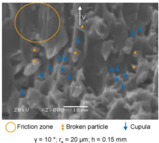
A considerable amount of cupula and broken particles is visible on
Fig. 13. This confirms the hypothesis of void nucleation starting from
decohesion between eutectic particles and aluminium matrix when damage initiation occurs. Finally, some sliding zones (circled in orange in thefigure) are observed, this can be due to a sliding between the chip and the workpiece while the crack is propagating and the chip re-moved.
Using EDS analysis, the nature of the cracked particles observed in
Figs. 12 and 13can be identified. The EDS map created and presented
in Fig. 14shows that the broken particles in sub-surface (circled in purple) are silicon (Si) particles. The mapping also helps to conclude that the micro-cracks (circled in orange) which is perpendicular to the Fig. 11. Burr with chamfer formation, frames from ultra-high-speed camera.
Fig. 12. Postmortem micrographs of a generated burr with chamfer.
Fig. 13. SEM picture of the chamfer generated during burr with chamfer formation. (For interpretation of the references to colour in the text, the reader is referred to the web version of this article.)
chamfer’s surface are propagating along the interdendritic zones. No trace of Mg or Fe compounds are found near the cracks of broken particles, indicating that damage occurs only inside the interdendritic zones.
High speed camera frames presented inFig. 15a show the formation of a burr without chamfer.The video of this burr formation is available here. It appears to be formed by a significant plastic deformation of the exit edge of the workpiece. The video observation indicates that the deformation in that particular instant is significantly high and that the edge of the workpiece is compressed under the cutting edge and goes beyond the exit surface. This phenomenon creates a slight decrease of the effective uncut chip thickness until no chip is formed. This decrease allows, thereafter, a pure elastic backflow of the sample at the end of the cut as it is unloaded suddenly. This is confirmed byFig. 15b which represents the relationship between the effective uncut chip thickness evolution (heff) with respect to the distance between the tool edge and
the exit surface (de) directly measured on the pictures ofFig. 15a.
To further understand the incidence of the burr without chamfer formation, a micrograph has been carried out. The micrograph, pre-sented inFig. 16shows a crack initiation along an inter-dendritic zone (delimited by orange circle in thisfigure). Right after this crack, a small cavity is observed. This crack propagation may be driven by the state of stress, in particular the stress triaxiality (η) around the cutting zone. The stress triaxiality has been demonstrated byRice and Tracey (1969)
to be one of the most important factor influencing the work material strain at fracture: the strain at fracture in tension (η > 0) is lower than that in compression (η < 0). That could explain the reason of an in-itiation of a crack yet no propagation occurs until the total fracture of the edge and creation of a burr with chamfer. Finally, at the end of the cut, the sample edge is exceedingly tilted to be in contact with the cutting edge of the tool. This is the reason why the tip of the burr, circled in purple inFig. 16, is in fact the initial surface before cutting.
4.2. Variability analysis
As explained in Section2.1, tests have been repeated three times. The aim was to analyse the results variability due to a hypothetic innate microstructural influence. TheFig. 17represents one of the burr height distributions (in light blue) with respect to uncut chip thickness for every repetitive test. Furthermore, purple and orange dots are plotted to represent burr with and without chamfer respectively. The graphic shows that the variability is more or less significant depending on the uncut chip thickness. This tendency is applicable to all tested cutting tool geometries, as it can be seen in the otherfigures presented in Supplementary material 1.
For low uncut chip thickness, the variability is quite good and the data distribution centred. For these cutting conditions, the mechanism involves a“low” plastic deformation, which reduces the microstructure dependency of the burr formation. As for high uncut chip thickness (here from h equal to 100 and 150μm), the average burr height is constant but the distribution spreads wider. This is predictable because of the microstructural dependence of the burrs with chamfer formation. Finally, between both extreme conditions, the burr with chamfer height distribution is centred. On the contrary, the burr without chamfer height distribution is more random and its difference from one test to another is relatively high. The proportion of the burr type along the edge of the workpiece is, for this part, quite repeatable, as shown in
Fig. 18. This may be the consequence of the microstructural effect
de-scribed in Section 4.1. In some regions, the eutectic zone is bigger, which allows a lower fracture strain due to more silicon particles acting as defect initiating voids. The initiation and propagation of a crack is then favoured. This explains the creation of both types of burr. As for the burr without chamfer variation, it could be explained by the den-drite size or SDAS. The higher the denden-drite size, the higher the plastic strain allowed before fracture.
4.3. Effect of uncut chip thickness on burr formation and morphology AsRégnier et al. (2016)demonstrated, one of the major parameter affecting burr formation is the uncut chip thickness. As shown inFig. 18
and as supplementary material 1 for the other cutting tool geometries, low uncut chip thickness produces mainly burr without chamfer. The lower uncut chip thickness of the study produces at least 90% of burr without chamfer for any conditions. This observation is coherent with respect to the formation analysis of burr without chamfer made in Section4.1. As mentioned byAbushawashi (2013), cutting at a low uncut chip thickness exhibits a large combined shear-compression zone (η < 0) in front of the cutting zone. Since low stress triaxiality causes a high strain at fracture, the formation of burrs without chamfer at low uncut chip thickness is logical. Nevertheless, as the alloy used for this study is quite heterogeneous, the strain at fracture intensity is not constant along the sample and between the samples. This explains the reason of a significant variability of burr without chamfer and of the
appearance of both burr types on the same sample.
On the other hand, higher uncut chip thickness produces more burr with chamfer because the combined shear-compression zone is replaced by a shear-tension one. As a result, the stress triaxiality allows a lower strain at fracture. The crack propagates until it reaches the exit surface of the workpiece. Between these extreme conditions, both types of burr can be produced with different proportions within the specimen width caused by the microstructure and the rake angle.
Not only burr height or burr type distribution are affected by uncut chip thickness, but chamfer height, whose evolution is shown inFig. 19
and in Supplementary material 2, is also impacted. It is observed that the average chamfer height’s absolute value is considerably increasing with respect to the increase of the uncut chip thickness. This could be due to a larger strain zone produced, leading to a wider affected zone under and in front of the tool.
As for the chamfer depth, its evolution is quite proportional to the chamfer height. This implies that the chamfer angle seems to be Fig. 15. Burr without chamfer formation (a), and evolution of effective uncut chip thickness heffwith respect to the distance between the cutting edge and the exit surface de(b).
independent of this cutting parameter. As shown in Fig. 20 and in Supplementary material 3, a slight decrease can be observed but the value is almost constant and around 30°. This might be explained with digital image correlation analysis and numerical simulations which will be carried out in the near future.
5. Analysis of burr accumulation in successive passes
Burr accumulation is the increase of a burr length in successive passes. It is thought to be the cause of high burr height obtained during shoulder milling after several teeth cut with decrease uncut chip thickness.Fig. 21and the associated supplementary material 4 show the evolution of this phenomenon for three passes. The graph shows the difference of evolution between burrs with and without chamfer. In one hand, a burr without chamfer will see its height increased in successive Fig. 16. Postmortem micrograph of a burr without chamfer. (For interpretation of the
references to colour in the text, the reader is referred to the web version of this article.)
Fig. 17. Effect of uncut chip thickness on burr height. (For interpretation of the references to colour in the text, the reader is referred to the web version of this article.)
Fig. 18. Effect of uncut chip thickness on burr type distribution along the exit edge.
Fig. 19. Effect of uncut chip thickness on chamfer height.
Fig. 20. Effect of uncut chip thickness on chamfer angle evolution.
passes as predicted. In the other hand, burrs with chamfer seem not to be affected by the accumulation of passes. A better comprehension of burr accumulation behaviours can be obtained by analysing the sam-ples’ images obtained by high speed camera.
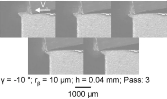
TheFig. 22shows video frames of the third pass for the same cutting condition presented inFig. 18.The video of the burr accumulation is available here. It is observed that the burr accumulation behaviour is quite similar to that of the original burr without chamfer. The strain causes the burr tilt around its root then the cutting edge continues its way without cutting anything.
Sometimes, the accumulation may not occur. After some passes the burr is removed and a burr with chamfer is created. The explanation could arise from two phenomena. A first assumption is the micro-structure effect; in successive passes, the subsurface changes because of the heterogeneous nature of the material. For the same reasons that the burr type is not uniform along the edge of the sample, the burr formed at a specific location during previous pass could not be the same type of burr formed in the current pass.
A second hypothesis is that the uncut chip thickness is lower than the depth of the crack initiated during the precedent pass. When the tool approaches the crack, the edge will push the surface and hence propagate the crack.
As for the burrs with chamfer, the evolution of the chamfer depth with respect to the number of passes is presented in Fig. 23and in Supplementary material 5.The video is available here. The graphic is combined with the images of the burr evolution in successive passes. Thefirst pass produces an average chamfer depth of 200 μm. The uncut
chip thickness (here 100μm) is lower than this chamfer depth, in-dicating that by the end of the cut, the effective uncut chip thickness decreases. This chamfer shape implies that the cutting forces are getting lower and lower once the cutting edge is close to the end of the cut. The deformation engendered is not high enough to generate a new burr with chamfer. Finally, the third pass generates a new burr with chamfer because the reduced chamfer depth is now slightly lower than the uncut chip thickness.
Sometimes, a burr with chamfer can be transformed into a burr without chamfer. This phenomenon may occur when the uncut chip thickness is slightly lower than the chamfer depth. The material af-fected by the strain in subsurface is deeper than the chamfer depth which allows the same mechanism than that from the formation of a burr without chamfer.
6. Conclusion
The present work allows the understanding of burr formation me-chanisms during orthogonal cutting of Al-Si aluminium alloy and the burr accumulation in successive passes. Two different types of burr are observed in relation with cutting conditions, work material micro-structure and mechanical behaviour. New parameters are proposed to describe the burr with chamfer more precisely and constitutes an im-provement of its characterisation.
- The corner radius (Cr)
- The chamfer height (Ch)
- The chamfer depth (Cd)
- The chamfer angle (Γc)
The morphologies of both burr types are also examined, using dif-ferent observation methods: high speed camera frames, micrographs, and SEM images combined with EDS analysis. Moreover, precise geo-metrical characterisation of burr is achieved using laser profilometer and distribution analysis. These analyses provide useful information on burr generation mechanisms. A burr with chamfer is generated by high localized strains combined with the tool movement, inducing a crack initiation and ensuing propagation. The beginning of the formation mechanism of a burr without chamfer is similar to the burr with chamfer. A localized strain is induced by the tool approaching the exit surface. However the strain is not high enough to initiate or propagate a crack. The edge of the workpiece will tilt without sufficient damage to break.
Investigations on burr production variability have been carried out to analyse the influence of the material heterogeneity. The evolution of the burr type distribution is quite repeatable. However, the hetero-geneity of the material produces a considerable variability of the burr height.
The effect of the uncut chip thickness on the burr formation has been also investigated. This cutting parameter affected by the change of stress triaxiality intensity is the main factor influencing the burr for-mation phenomena. It is observed that increasing uncut chip thickness helps producing more burr with chamfer.
Finally, burr accumulation in successive passes is investigated. It is observed that the phenomenon occurs only for low uncut chip thick-ness, and the mechanism is similar to that leading to burr without chamfer formation. Sometimes the accumulation stops, and the burr removed.
While a burr with chamfer is produced, the phenomenon is more complex. If the uncut chip thickness is way lower than the chamfer depth, this chamfer depth will be reduced. If the uncut chip thickness is almost equal but still lower than the chamfer depth, the cut will gen-erate a burr without chamfer. Finally, if the uncut chip thickness is higher than the chamfer depth, a new burr with chamfer will be gen-erated.
Further scientific contribution would be focused on experimental Fig. 22. Movie frames of an accumulation pass.
approach using methodologies to quantify the strainfield generated in the workpiece during burr formation, by DIC technique. A second major advance would be to simulate the formation of the two different burr morphologies. Finally, the rake angle effect on burr formation as well as the edge sharpness one will be analysed.
Funding
This research did not receive any specific grant from funding agencies in the public, commercial, or not-for-profit sectors.
Acknowledgement
The authors would like to thank Rémi Martinez and Serge Quantin, from Montupet/Linamar, for their help regarding the contribution of microstructure on burr morphology. We would also like to thank Pierre Naisson from CERN and Vincent Moreau from CETIM for their advices and help on edge preparation.
Appendix A. Supplementary data
Supplementary material related to this article can be found, in the online version, at doi:https://doi.org/10.1016/j.jmatprotec.2018.02. 037.
References
Abushawashi, Y.M., 2013. Modeling of Metal Cutting As Purposeful Fracture Of Work Material. Ph.D. Thesis..
Bourlet, C., et al., 2016. Analysis and modeling of burr formation during the plane milling of cast aluminum alloy using polycrystalline diamond tools’. J. Manuf. Sci. Eng. 138 (8), 081010-1–081010-12.http://dx.doi.org/10.1115/1.4032584.
Chern, G.-L., 2006. Experimental observation and analysis of burr formation mechanisms in face milling of aluminum alloys’. Int. J. Mach. Tools Manuf. 46 (12–13), 1517–1525.http://dx.doi.org/10.1016/j.ijmachtools.2005.09.006.
Da Silva, L.C., et al., 2015a. Study of burr behavior in face milling of PH 13-8 Mo stainless steel. CIRP J. Manuf. Sci. Technol. 8, 34–42.http://dx.doi.org/10.1016/j.cirpj.2014. 10.003.
Da Silva, L.C., et al., 2015b. Study of burr height in face milling of PH 13-8 Mo stainless steel– transition from primary to secondary burr and benefits of deburring between passes. CIRP J. Manuf. Sci. Technol. 10, 61–67.
Gillespie, L.K., 1973. The Formation and Properties of Machining Burrs. Ph.D. Thesis.. Gillespie, L.K., Blotter, P.T., 1976. The formation and properties of machining burrs. J.
Eng. Ind. 98 (1), 66–74.http://dx.doi.org/10.1115/1.3438875.
Hashimura, M., Chang, Y.P., Dornfeld, D., 1999a. Analysis of burr formation mechanism in orthogonal cutting. J. Manuf. Sci. Eng. Trans. ASME 121 (1), 1–7.
Hashimura, M., Hassamontr, J., Dornfeld, D.A., 1999b. Effect of in-plane exit angle and rake angles on burr height and thickness in face milling operation. J. Manuf. Sci. Eng. Trans. ASME 121 (1), 13–19.
Hintze, J.L., Nelson, R.D., 1998. Violin plots: a box plot-density trace synergism. Am. Statist. 52 (2), 181–184.http://dx.doi.org/10.1080/00031305.1998.10480559. ISO 13715:2000– Technical drawings – Edges of undefined shape – Vocabulary and
in-dications (2000).
Iwata, K., Ueda, K., Okuda, K., 1982. Study of mechanism of burrs formation in cutting based on direct SEM observation’. J. Jpn. Soc. Precis. Eng. 48 (4), 510–515. Ko, S.-L., Dornfeld, D.A., 1991. A study on burr formation mechanism’. J. Eng. Mater.
Technol. 113 (1), 75–87.http://dx.doi.org/10.1115/1.2903385.
Kumar, S., Dornfeld, D., 2003. Basic approach to a prediction system for burr formation in face milling. J. Manuf. Processes 5 (2), 127–142. http://dx.doi.org/10.1016/S1526-6125(03)70048-6.
Nakayama, K., Arai, M., 1987. Burr formation in metal cutting. CIRP Ann.-Manuf. Technol. 36 (1), 33–36.
NF EN1706, 2010. Aluminium and Aluminium Alloys– Castings – Chemical Composition and Mechanical Properties.
Olvera, O., Barrow, G., 1995. An experimental study of burr formation in square shoulder face milling. Int. J. Mach. Tools Manuf. 36 (9), 1005–1020.
Régnier, T., et al., 2016. Experimental investigation and modelling of burr formation during orthogonal cutting of A356+0.5Cu aluminium alloy. In: 13th International Conference on HIGH SPEED MACHINING 2016. Metz, France. p. 6.
Rice, J.R., Tracey, D.M., 1969. On the ductile enlargement of voids in triaxial stressfields. J. Mech. Phys. Solids 17 (3), 201–217.
Schafer, F., 1975. Product design influences on deburring. Technical Paper. p. 12.
Toropov, A.A., Ko, S.-L., 2006. A new burr formation model for orthogonal cutting of ductile materials. Ann. CIRP 55 (1).
Wang, Q.G., 2003. Microstructural effects on the tensile and fracture behavior of alu-minum casting alloys A356/357. Metall. Mater. Trans. A 34 (12), 2887–2899.http:// dx.doi.org/10.1007/s11661-003-0189-7.