Science Arts & Métiers (SAM)
is an open access repository that collects the work of Arts et Métiers Institute of Technology researchers and makes it freely available over the web where possible.
This is an author-deposited version published in: https://sam.ensam.eu Handle ID: .http://hdl.handle.net/10985/20059
To cite this version :
Mohamad EL YOUSSEF, AbdelKader BENABOU, Thierry COOREVITS, Adrien VAN GORP, Stéphane CLENET, Pierre FAVEROLLE, Jean-Claude MIPO, Yannick LAVALLEY, Thomas LECUPPE - The effect of punching on electrical machine - International Journal of Applied Electromagnetics and Mechanics - Vol. 61, n°S1, p.S107-S114 - 2019
Any correspondence concerning this service should be sent to the repository Administrator : [email protected]
International Journal of Applied Electromagnetics and Mechanics
15th Int. Workshop on 1 & 2 Dimensional Magnetic Measurement and Testing, 2DM-Grenoble 24-26 Sept (2018) 1 IOS Press
The effect of punching on electrical machine
Mohamad EL YOUSSEF a, AbdelKader BENABOU b, Thierry COOREVITS a, Adrien VANGORP a, Stéphane CLENET b, Pierre FAVEROLLE c, Jean-Claude MIPO c, Yannick
LAVALLEY d, Thomas LECUPPE d.
a Arts & Metiers ParisTech; Mechanics, Surfaces and Materials Processing (MSMP); 8, boulevard Louis XIV 59046 Lille,France.
b Univ. Lille, Arts et Metiers ParisTech, Centrale Lille, HEI, EA 2697 - L2EP -Laboratoire d’Electrotechnique et d’Electronique de Puissance, F-59000 Lille, France.
c Valeo-2 Rue André Charles Boulle, 94000 Créteil, France.
d R.Bourgeois-25, Rue de Trépillot BP 1077 25002 Besançon, France.
Abstract. This work enlightens the impact of punching on a specific stator performances. Two specimens type are withdrawn
from a M330A35 punched lamination sheet. One type represents a closed magnetic circuit while the other represents two parts. Magnetic measurements are performed on both types. Measurements are compared with those performed on specimens cut by WEDM. The specific purpose of this paper is to investigate the impact of punching in presence of air gap which exist in electrical machines between rotor and stator. Therefore a dedicated device is developed in order to control airgap perfectly and FEM simulations are also presented to make results more accurate.
Keywords: Punching, Magnetic characterization, Stator.
1. Introduction
The punching process is based on a shearing phenomenon with a precisely shaped tool. Due to its cutting speed, it represents the widespread lamination cutting method. However, as any manufacturing process, it affects the material properties and leads to magnetic behavior degradation [1] [2] Globally, it leads to the decrease of the magnetic permeability and increase of the iron losses. Several studies have tried to define the impacted zone with different methods. Results show that punching could impact the material, depending on the cutting parameters, up to 10mm from the cut edge [3] [4].
Existing studies address the impact of punching on the magnetic behavior considering normalized characterization devices and the extrapolation of the results to real application is not necessarily straightforward because the effect of punching depends highly on the parameters of the process [5] [6].In addition, in the electrical machines, the air gape between stator and rotor belong to the magnetic circuit. So, how much punching could affect the machine performance?
In this paper, we propose an approach to characterize the effect of punching on samples collected from the manufacturing line of slinky stators, which enables to highlight the effect of the process on this specific geometry in presence of airgap.
2. Experimental conditions 2.1. Sample geometry
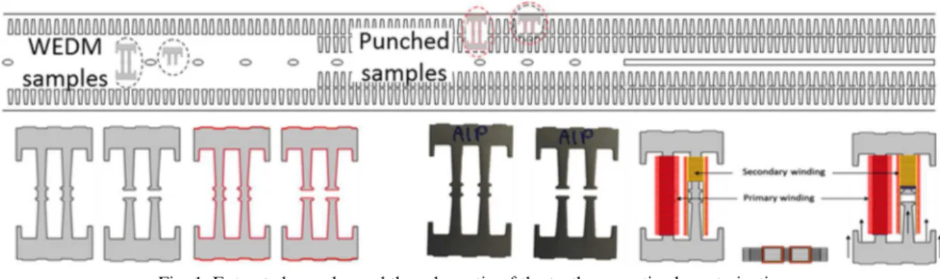
Two types of punched samples are considered: the first type represents a closed magnetic path (without airgap), the second one consists of two parts, which represent the upper and the lower parts of the first sample type. In fact, the slinky stator yoke fabrication is performed in several steps that allow extracting these two types of samples (Figure 1).
Each sample represents 5 stacked laminations. In order to estimate the impact of punching, the electromagnetic behavior of samples are compared with other samples having the same geometry and extracted from the same lamination sheet. They are reclaimed using the wire electrical discharge machining (WEDM) cutting method. This process is reputed by its precision and its limited impact on magnetic behavior among cutting process. Thus, the magnetic behavior of these samples will be considered as a reference.
2.2. Magnetic measurements
The same magnetic measurement method is applied on both samples type. A primary and a secondary windings are placed around teeth as it is shown in Fig. 1. The considered samples can be arranged to form a closed magnetic path, but with a non-constant cross-section. Thus, the estimation of the magnetic flux density is not straightforward as it will not be homogeneous. Therefore, it is chosen to consider the evolution of the magnetic flux and the imposed Ampere-turns (NI) in order to evaluate the impact of the process. For more visibility, sometimes an average section will be referred to the magnetic circuit. Thus, magnetic behavior will be presented as an evolution of ~B (~H).
B=Flux/average section (1)
H=NI/average length (2)
Measurements have been performed with sine waveforms on the secondary coil in a frequency range of [10 Hz—1.5 kHz] and from ~0.2 to ~1.5 T for closed samples. While the open samples in a frequency range of [50 Hz—1.5 kHz] and from ~0.2 to ~1.2 T.
Fig. 1. Extracted samples and the schematic of the teeth magnetic characterization
2.3. Experimental device for open samples.
In order to investigate the impact of punching on the magnetic behavior in the presence of air gap accurately, a specific characterization device is developed (Erreur ! Source du renvoi introuvable.). It allows controlling the airgap between parts within µm. During measurements, one part is clamped and the position of the second part is settled via a micrometric screw. The air gap is measured directly using an LVDT ((Linear Variable Differential Transformer) displacement sensor according to Abbe principle.
When both parts are in contact, the airgap is considered null. However, the contact between surfaces is not perfect. In fact, the stack of cut sheets is performed manually by sticking sheets together. Therefore the surface of the stack is not perfectly plane. Some profile measurements using an optical roughness meter are performed on sample parts. Results show that deviation between the sheets could reach 100µm.
To be more accurate, an effective measurement strategy was set up. Samples are placed in the same
way they are, during magnetic measurements, and 3D measurements are realized using a ZEISS Coordinate-measuring machine (CMM) (Fig. 3). The parasitic air gap between parts are calculated as follows:
1. We got two plans corresponding for both parts using the least square method.
2. The deviation of points from plans is calculated
3. Summing deviation of two parts points
4. Define a plane perpendicular on (xy) and tangent on the sum of deviations using a
constrained least square algorithm.
5. Make the deference between plan and deviation points.
2.4. Impact of parasitic air gap
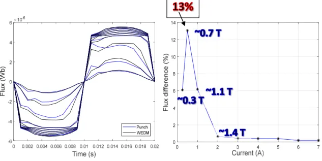
In order to, quantify the impact of the parasitic air gap on our measurements. The problem is simulated using a 3D FEM model. Scattered points corresponding to each sample are imported into a computer-aided design software (CAD) in order to take into account the misalignment of sheets. Geometries including parasitic air gap are simulated with ANSYS (Maxwell). Raw material properties are used for both samples. This simulation does not take into account the effect of punching or the effect of WEDM. The aim here is to quantify the maximal error due to the geometry difference.
In Fig. 4, we present the evolution of the generated flux for different imposed current levels at 50Hz in coils which correspond to the primary winding in our device. The blue curves represent the generated flux for the punched sample geometry while the black curves correspond to the WEDM one. Result show that the highest difference peak is around 13% of the generated flux. As far as we are closer to the saturation level the difference will decrease and will be lower than 0.5%.
3. Impact of punching on closed samples.
In Fig. 5, we present the hysteresis loops Φ(N·I) corresponding to the single core samples at 50Hz,
Fig. 3. Parasitic air gap measurements.
Punch__C for punched samples and WEDM__C for wire cut samples. It is clear that punching has a drastic effect on the magnetic properties, a significant degradation of the permeability is observed. Thus, extra Amperes-Turns are needed in case of punching samples to reach the same flux level. For example, to get 3.3µwb in case of punching, we need 3 times N.I than those needed in the WEDM case.
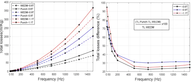
Also, punching effect is well pronounced on total losses. In (Fig. 6) we present total losses evolution with frequency for different flux level. The total losses difference decreases with frequency. It could reach 90% at 50Hz (~1.1T). While for high frequencies the difference is almost constant around 25% (~1.1T). This phenomenon could be explained that punching affects mainly the hysteresis losses which their portion in front of eddy current losses decreases with frequency.
4. Impact of punching in presence of airgap
Magnetic measurements are performed on open samples for different air gap value (0-300µm). The
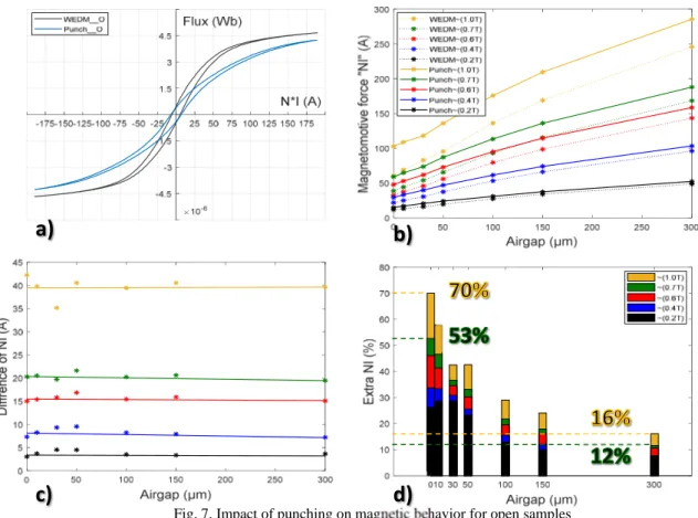
Fig. 7a presents the hysteresis loops Φ(N·I) corresponding to the open core samples when they are in
contact (no air gap) at 50Hz. We notice that magnetic behaviors of both samples are deteriorating in comparison with closed samples (Fig. 7). This could be referred due to the parasitic air gap which affects significantly the magnetic behavior. Nevertheless, the impact of punching is clearly emphasized when compared with the wire-cut sample. Thus, it was important to quantify the impact of the parasitic air gap in order to separate its impact from the punching one.
The Fig. 7b represents the evolution of needed Ampere-turns, to reach different flux levels, with airgap size. We notice that the difference between NI for both samples remain almost constant for different air gap values Fig. 7c. This is fully consistent, as magnetic behavior is linear in the air. As shown in Fig. 7d, the global impact of punching decreases with air gap increase and it could reach
Fig. 5. Impact of punching on hysteresis loop for closed samples.
16% to around ~1T. Taking into account the effect of parasitic air gap (13%), the difference will be around 14.5%.
5. CONCLUSION*
This paper studies the effect of punching on a specific stator geometry. Magnetic measurements are performed on samples extracted from punched lamination at different steps. A specific device allowing to control air gap is also developed. In presence of ~300µm air gap at least 14.5% of additional current is needed in order to reach the same flux level. In fact, we have to mention that the difference should be higher, because even WEDM has an impact on magnetic properties. Finally, we can deduce that it is worthy to investigate more deeply the impact of the manufacturing process in order to produce more efficient electrical machines.
References
[1] P. Baudouin, M. De Wulf, L. Kestens, and Y. Houbaert, “The effect of the guillotine clearance on the magnetic properties of electrical steels,” J. Magn. Magn. Mater., vol. 256, no. 1–3, pp. 32–40, Jan. 2003.
[2] M. Z. Salih, B. Weidenfeller, N. Al-hamdany, H.-G. Brokmeier, and W. M. Gan, “Magnetic properties and crystallographic textures of Fe 2.6% Si after 90% cold rolling plus different annealing,” J. Magn. Magn. Mater., vol. 354, pp. 105–111, Mar. 2014.
[3] F. Ossart, E. Hug, O. Hubert, C. Buvat, and R. Billardon, “Effect of punching on electrical steels: Experimental and numerical coupled analysis,” IEEE Trans. Magn., vol. 36, no. 5, pp. 3137–3140, 2000.
[4] T. Nakata, M. Nakano, and K. Kawahara, “Effects of stress due to cutting on magnetic characteristics of silicon steel,” IEEE Transl. J. Magn. Jpn., vol. 7, no. 6, pp. 453–457, 1992.
[5] A. Kedous-Lebouc, O. Messal, and A. Youmssi, “Joint punching and frequency effects on practical magnetic characteristics of electrical steels for high-speed machines,” J. Magn. Magn. Mater., vol. 426, pp. 658–665, Mar. 2017. [6] Z. Gmyrek and A. Cavagnino, “Analytical method for determining the damaged area width in magnetic materials due to punching process,” in 37th Annual Conference of the IEEE Industrial Electronics Society-IECON 2011, 2011.
Fig. 7. Impact of punching on magnetic behavior for open samples