Science Arts & Métiers (SAM)
is an open access repository that collects the work of Arts et Métiers Institute of Technology researchers and makes it freely available over the web where possible.
This is an author-deposited version published in: https://sam.ensam.eu
Handle ID: .http://hdl.handle.net/10985/8215
To cite this version :
Sajid-Ullah BUTT, Jean-François ANTOINE, Patrick MARTIN - An Analytical Model for Repositioning of 6 D.O.F Fixturing System Mechanics & Industry Vol. 13, n°3, p.205217 -2012
An Analytical Model for Repositioning of 6
D.O.F Fixturing System
Sajid Ullah BUTT
∗1, Jean-François ANTOINE
1,2, and Patrick
MARTIN
11LCFC, Art et Métiers, 4 Rue Augustin Fresnel, 57078 Metz, France 2IUT Nancy-Brabois, département GMP, Le Montet, Rue du Doyen Urion, 54601
Villers-lès-Nancy, France
Abstract
Dimensional errors of the parts from a part family cause the initial misplacement of the workpiece on the fixture affecting the final product quality. Even if the part is positioned correctly, the external machining forces and clamping load cause the part to deviate from its position. This deviation depends on the external load and the fixture stiffness. In this article, a comprehensive analytical model of a 3-2-1 fixturing system is proposed, consisting of a kinematic and a mechanical part. The kinematic model relocates the initially misplaced workpiece in the machine reference through the axial advancements of six locators taking all the fixturing elements to be rigid. The repositioned part then shifts again from the corrected position due to the deformation of fixturing elements under clamping and machining forces. The mechanical model calculates this displacement of the part considering the locators and clamps to be elastic. The rigid cuboid baseplate, used to precisely re-locate the workpiece, is also considered elastic at the interface with the locators. Using small displacement hypothesis with zero friction at the contact points, Lagrangian formulation enables us to calculate the rigid body displacement of the workpiece, deformation of each locator, as well as the stiffness matrix and mechanical behavior of the fixturing system. This displacement of the workpiece is then finally compensated by the advancement of the six axial locators calculated through the kinematic model.
keywords: fixturing system, fixture design, mechanical mod-elling, optimal balancing, positioning error, Lagrangian formu-lation
1
Introduction
Fixtures are used to support, locate and hold a workpiece at a desired orientation in machine space during manufacturing [1, 2, 3]. The quality of a part is influenced by the capability of a fixture to secure and locate it on the machine considering different functional conditions during fabrication. The design of fixtures is important to precisely hold the workpiece in place and compensate the errors during machining or assembling operation to ensure high product quality.
The need for high quality production, at low cost, has accelerated the re-search efforts in fixture design aiming at producing cost effective products with-out compromising on quality. To cope with current market demand, Ryll et al. [1] emphasize on the need for "intelligent" fixtures which should be capable of self-configuring; reducing and compensating dimensional errors; providing stability and adapting clamping forces to guarantee optimum performance.
During production, two rough parts from the same part family can have small dimensional variations before machining operation. The rough work-piece, placed on the locators, may not be completely included in the required position due to these geometrical variations, which cause the workpiece to be wasted. To avoid the time and the material loss, it is necessary to place each new part precisely. This placement necessitates the mobilisation of ma-chine tool which is only possible on the mama-chines having large number of DOF and high number of geometric transformations. If a processing operation (machining or assembling) only requires a low number of axes or only small displacements, the choice of a 5-axis machine is not an economically feasible one.
setup planning, fixture planning, unit design and verification. This work fo-cuses on the fixture planning which ensures the precise placement of the work-piece with respect to machine tool reference. To do so, all possible errors should be eliminated or compensated. The main causes of machining errors, which in turn cause misalignment of the workpiece, are the following:
Generally, the fixture design involves four main steps [4, 5, 6] which are; setup planning, fixture planning, unit design and verification. This work fo-cuses on the fixture planning which assures the precise placement of the work-piece with respect to machine tool reference. To do so, all possible errors should be eliminated or compensated. The main causes of machining errors, which in turn cause misalignment of the workpiece, are the following:
1. Error due to placement of locators
2. Error due to geometrical/form defects of workpiece
3. Deformation under clamping and machining forces
4. Machine tool error or machine kinematic error, thermal error and me-chanical error
Here, we shall state a brief literature review of the above mentioned causes of errors.
The first stage of the fixture design is the choice of fixturing configuration. Somashekar [7] proposed a model to select the primary, secondary and tertiary planes of the workpiece, and the number of fixturing elements based on the moment and force acting on the workpiece. Menassa & Devries [8] determined the secondary and tertiary planes with their respective locator positions con-sidering the primary locating details to be known. Roy & Liao [9] relocated the supports on a 3-2-1 fixturing system considering the stability of the work-piece by applying a virtual wrench. System stability is enhanced by increasing
the area of the triangle formed by three supports on the primary plane. Li & Melkote [10] presented a model to improve workpiece location accuracy by fixture layout optimization taking fixture-workpiece contact deformation to be elastic.
Local geometrical defects of rough workpiece also cause its dislocation from the desired position. A bed of nails type fixture [11] can be used to hold thin or soft workpieces with reduced deformation. Small Displacement Torsor (SDT)[12,13] approach is used to find the localization error of the workpiece. Using the same approach, the geometrical deviation of machining surface rela-tive to its nominal position is presented in [14]. Asante [15] proposed a model using HTM and SD to calculate the positioning errors of the workpiece on a 3-2-1 fixture. Overall positioning error is taken as the sum of workpiece geometric error, locator geometric error and clamping error.
The workpiece shifts from its original position under clamping and machin-ing forces due to the deformation of elastic fixturmachin-ing elements. Clampmachin-ing and machining forces are applied once the workpiece is initially located in the fix-ture. The effect of clamping on the workpiece displacement and the optimized or minimum clamping forces models are presented in [16, 17, 18]. Jayaram et al. [19] calculated the minimum stiffness of each locator required to with-stand the applied load with acceptable workpiece displacement considering the workpiece to be rigid. Raghu & Melkote [20] predicted the final position and orientation of the workpiece due to fixture geometric errors using the part loading chart [21] and fixture workpiece compliance [17].
Significant work has been performed on the determination of the machine tool error [22, 23, 24, 25, 26]. It is impossible to eliminate machine tool er-ror due to structural and production limitations, therefore it is necessary to compensate them. The compensation can be achieved either by changing tool
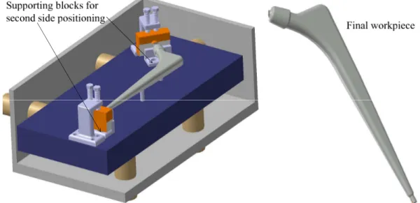
path, moving the cutting tool, or moving the workpiece in the machine coordi-nate system. The easiest error compensation method is changing the cutting tool path using the NC part program [27,23,28, 26] as shown in figure 1, but this compensation requires 4 or 5-axis machine tools to perform the necessary transformation.
Figure 1: Compensation through NC part program
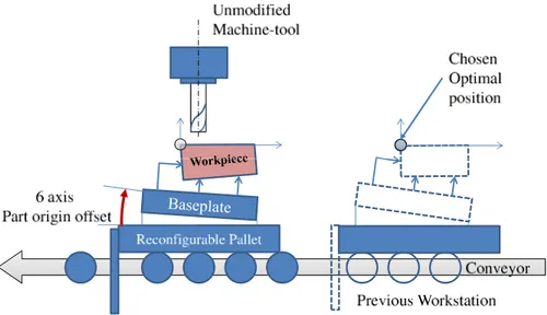
Figure 2: Compensation through workpiece repositioning
workpieces and which is capable of performing a 6-DOF repositioning in the machine coordinates without the use of a 4 or 5-axis machine. The proposed repositioning principle is shown in figure 2, where a high quality baseplate is introduced in between the locators and the workpiece. The workpiece is assumed to be fixed rigidly on the baseplate and any modification of its position can be performed through repositioning of the baseplate on locators. Baseplate repositioning will eliminate the position uncertainty due to local geometric errors and avoid the use of high DOF machines at each machine center; instead, a single fixture can perform the workpiece repositioning at each machine center. The proposed fixturing system is capable of;
1. 1. Determining the relative positioning error (Due to geometrical defects or due to deformation under load) between the workpiece and the tool before and during machining or between the two parts during assembling 2. 2. Ensuring the axial displacement of 6-locators in order to reorient the
workpiece at an optimal position
The proposed system aims to perform automatic on-line or off-line work-piece repositioning operation. It ensures the pre-positioning of complex parts for precise machining operations. The system can also be used on the auto-matic production lines where the number of axis is limited for each station. The proposed system allows better positioning of the workpiece on the fixture, hence limiting allowances. In this article, the kinematic and mechanical model of the proposed fixturing system is presented.
The article is composed as follows; section 2 presents the kinematic model of the reconfigurable fixturing system, by considering large displacement trans-formation for the repositioning of the workpiece. The kinematic model is illus-trated through CATIAr simulation. Section 3 discusses the mechanical model
assembly is clamped while machining forces are introduced. A case study demonstrates the mechanical model using the Lagrangian formulation and small displacement transformation (SDT). This case study identifies the vi-brational attributes of the fixturing system, while taking into consideration the stiffness of each locator and clamp, as well as the mass of the baseplate-workpiece assembly.
2
Kinematic model of the fixturing system
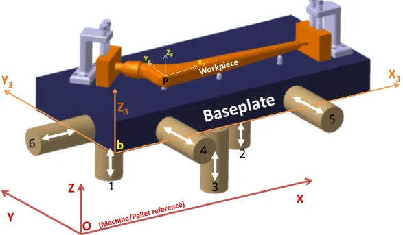
Figure 3: Proposed fixturing system
The proposed fixturing system consists of a set of six locators (whose po-sitions and orientations are defined through locating holes on the machine table/pallet), a cuboid baseplate, and a workpiece (hip prosthesis) fixed on the baseplate as shown in fig 3. The locators are assumed to be in a 3-2-1 fixturing configuration and possess only one axial DOF. The lateral position of each locator is chosen taking into account the constraints of accessibility
and stability of the workpiece as well as manufacturing knowledge. It is also assumed that the workpiece is mounted rigidly on the baseplate and that no additional deformation occurs between workpiece and baseplate except those caused when clamping the workpiece.
Assuming that unknown initial position could imply large displacements (LD) of workpiece during correction phase, the kinematic model is built using homogeneous transformation matrices (HTM) and LD formulation. The geo-metrical properties of the baseplate enable us to calculate the position of the baseplate from the positions of six locators. The position of the workpiece is obtained as per the hypothesis of the rigid workpiece-baseplate contact. This allows the kinematic model to be more efficient and repeatable. In addition, it would be easier to manoeuvre the workpiece-baseplate assembly through the locators. In the proposed fixturing system, the workpiece is located and clamped on the baseplate forming a single rigid assembly.
2.1
Formalization
It is assumed that the positioning error of the baseplate is negligible as compared to the positioning error of the workpiece. For the workpiece reposi-tioning, initial position of the workpiece can be measured through CMM and the whole workpiece-baseplate assembly can then be placed on the fabrication machine. The initial position of the workpiece is compared with its required position. Repositioning is necessary if the difference between initial and final position is beyond limits. There needs to be a proper mathematical formu-lation to perform the transformation of the workpiece from its initial to final position with the help of six locators which are able to move only axially.
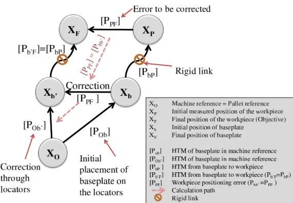
Positioning transformation scheme of the proposed fixturing system is shown in figure 4. Here, Xi represents the position vector of reference i while [Pij]
Figure 4: Transformation of reference axes for kinematic model transformation
represents the transformation matrix from position i to j. The HTM of the baseplate with respect to machine reference ([POb]) are calculated from the
locators’ initial positions. The transformation of the workpiece relative to the machine ([POP]) can be measured through CMM. Thus the transformation of
workpiece with respect to baseplate ([PbP]) can be calculated.
[PbP] = [POb]
−1
[POP] (1)
The final position of the workpiece with respect to machine coordinate (XF)
is the required position of the workpiece and is known through part program. The reorientation of the baseplate ([Pbb′]) enables us to reorient the workpiece ([PP F]) as the contact between the baseplate and workpiece is supposed to be
positions (XP and XF) of the workpiece are known, we get the HTM equations as, [POF] = [POb′][Pb′F] = [POb′][PbP] (2) [POb′] = [POF][P −1 bP]
Equations 1 and 2 give the final HTM of the baseplate in the machine coordinate system which can be written in terms of locators’ positions in HTM form as, [POb′] = a′ 3 a′2 a′1 x′b b′ 3 b′2 b′1 y′b c′ 3 c′2 c′1 z′b 0 0 0 1 = [POF].([POb]−1.[POP])−1 (3) where, a′ i, b ′ iand c ′
iare the components of unit normal vectors of each plane and
[POb′] is the absolute HTM of the baseplate with respect to machine coordinate system needed to reorient the workpiece at the position required by the part program. Due to no friction hypothesis, the final calculated position of each locator will not be in line with its axis, so that repositioning is not possible. To solve this issue, the cuboid formed by the actual locators positions is centred with the cuboid formed by the final calculated positions. For this purpose, the contacting points’ positions along the axis of each locator are calculated on respective surface by using the equation of each surface. For example z position is fixed for locator 1. The final plane equation of primary surface can be calculated as, a′ 1x ′ 1+ b ′ 1y ′ 1+ c ′ 1z ′ 1 = D1 (4)
where, D1 is the vertical distance of the plane from machine origin. The point
z∗
on the plane, which corresponds to the fixed lateral position of locator 1(x1,
y1), can be found by,
z∗ 1 = D1− a′1x1− b′1y1 c′ 1 (5)
Similarly, the axial displacement of all the locators can be calculated to center the cuboid formed by the locators with the one required to reposition the workpiece.
2.2
Case Study
In order to validate the kinematic model, a case study is performed on a hip prosthesis repositioning through CATIAr simulation. A CPTr 12/14
Hip Prosthesis by Zimmer [29] is chosen as a demonstrative workpiece. This workpiece is fabricated in a single unit, by employing a precise cost effective machining process.
Prosthesis replacement of large human joints is one of the most promising methods in treating post-traumatic and degenerative dystrophic joint diseases. In 2006, the annual number of prosthesis replacements of hip joints was 300K in the USA, 60K in Germany and 20K in Russia [30]. Due to the nature of custom design process, the CNC milling fabrication process is a suitable choice using a milling operation [31]. Here, it is assumed that the milling operation is performed initially on one half of the workpiece and then the workpiece is inverted to perform the machining in the remaining half part.
The hip prosthesis is created in CATIAr and its original dimensions are
slightly increased and supports are added to obtain a rough workpiece before machining. It is supposed that this workpiece is clamped rigidly on the base-plate which is further located through six rigid locators. An inverse impression
of the workpiece (like a half die) is created with the original hip prosthesis di-mensions and is placed on a fixed position with reference to the machine origin. This position represents the tool path on the machine as the tool moves with reference to machine and not with reference to workpiece. A boolean operation is performed to simulate the machining operation by subtracting the common material from the workpiece. Two slots are made during machining of the first half part which will help to place the workpiece on two well positioned blocks after inverting.
2.2.1 Data input
The analytical model is implemented in a worksheet directly linked to the CATIAr model which furnishes the initial position of roughly placed
workpiece(POP of equation 1). This position should be obtained by CMM
in real environment as presented in table 1 along with the initial positions of all the locators. The initial position of the baseplate (POb ) is a function of
locators’ positions. The machining performed on this initially roughly placed workpiece is shown in figure 5. The workpiece should be repositioned at the required position to perform a precise machining operation. This final position (POF of equation 2) is known by the part program and is shown in the table
2.
2.2.2 Results
The algorithm calculates the final locators’ positions (POb′) to reorient the workpiece at therequired position. This final calculated position of each locator is shown in table 3(a) by rounding off the values to two decimals represent-ing the locators’ advancement precision of 1µm. These calculated values are again introduced as input to CATIAr model to check the final attained
po-Table 1: Input data from the initial positions
(a) Initial locators’ positions (Axial positions are highlighted) Locator no x (mm) y (mm) z (mm) 1 70 100 15.00 2 180 100 15.00 3 120 40 16.00 4 70 10.00 40 5 180 11.00 40 6 10.00 60 40
(b) Initial workpiece position Plane Angle Degree Point P mm
αi 0.52 xP 103.5
βi -0.96 yP 60.57
γi 0.01 zP 70.67
Figure 5: Machining performed on the workpiece placed at the initial position
sition. This relocates the workpiece-baseplate assembly and the machining is re-simulated which can be seen in figure 6. The 1µm precision constraint, by rounding off the locators advancements, causes the final corrected position to be slightly different from the required one (table 2). The error between the final and required position is shown in table 3(b).
Table 2: Chosen final position of the workpiece Plane Angle Degree Point P mm
αf 0 xF 100
βf 0 yF 60
γf 0 zF 70
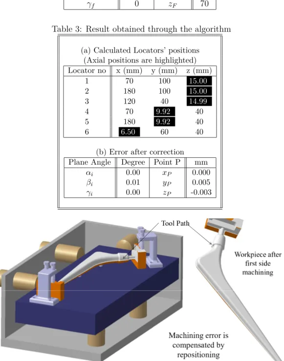
Table 3: Result obtained through the algorithm
(a) Calculated Locators’ positions (Axial positions are highlighted) Locator no x (mm) y (mm) z (mm) 1 70 100 15.00 2 180 100 15.00 3 120 40 14.99 4 70 9.92 40 5 180 9.92 40 6 6.50 60 40
(b) Error after correction Plane Angle Degree Point P mm
αi 0.00 xP 0.000
βi 0.01 yP 0.005
γi 0.00 zP -0.003
The workpiece is then inverted and clamped on the baseplate. Two slots, created during the machining of the first side, help to place the workpiece on two precisely placed blocks. This helps to place the workpiece precisely with respect to the first machined surface. Same procedure is performed for the repositioning of the second side of the prosthesis on the baseplate. The final assembly and end-product after the repositioning and machining simulation on the second face of the prosthesis is shown in figure 7, and the error with respect to required position of the prosthesis is shown in table 4.
Figure 7: Machining performed on the workpiece after repositioning the second side and the final product
Table 4: Error of the second face after correction Plane Angle Degree Point P mm
αi 0.00 xP 0.002
βi 0.00 yP 0.00
γi 0.00 zP 0.00
The above example validates the algorithm. For the second face reposi-tioning, angular error is almost zero because of input data being the output of the first correction, which was in the precision range. The procedure does not
change with the complexity of the workpiece, therefore, the same repositioning procedure can be used for more complex parts.
2.2.3 Robustness of the model
The workpiece position uncertainty can be calculated from the Plücker coordinates[32] as the function of locators’ advancements precision. In our case, using the locators’ input positions (table 1), the uncertainty at reference point P (table2) is a function of six advancements,
δxP δyP δzP δα δβ δγ = dx6− 6dy4 11 + 6dy5 11 − 4dz1 11 + 4dz2 11 18dy4 11 − 7dy5 11 + 4dz1 11 + 10dz2 33 − 2dz3 3 8dz1 11 − 46dz2 33 + 5dz3 3 dz1 110+ dz2 132− dz3 60 dz1 110− dz2 110 −dy4 110+ dy5 110 (6)
where, dz1, dz2, dz3, dy4, dy5 and dx6 are uncertainties of the locators’
ad-vancements, in our case, assumed to be 0.01 mm maximum.
3
Mechanical model
In the previous section, a kinematic model is presented which is capable of correcting the positioning error if the initial and required positions of the workpiece are known. In reality, locators can deform under the weight of the baseplate, as well as under static and dynamic forces acting on the workpiece-baseplate assembly. The workpiece-baseplate, repositioned by kinematic model, is clamped to the pallet to remain at the corrected position and undergo the machin-ing forces. In fact, these mechanical actions will imply displacements on the baseplate-workpiece assembly, so that the previously corrected position gets
modified which could result in the part being dislocated and wrongly pro-cessed.
In this section, a mechanical model of the fixturing system is formulated to calculate the displacement of the workpiece caused by the deformation of elastic fixturing elements under load. For this purpose, the overall stiffness and mass of the whole fixturing system are calculated considering the locators as being the elastic elements with negligible masses and the workpiece-baseplate assembly as a rigid mass element. The analytical formulation is used because it calculates the mass and stiffness matrices quickly for any configuration and advancements of locators. This analytical mechanical model is formulated and solved in a computational system (Mathematicar) to obtain the result. As the
deformation must remain small for the system reliability and lifetime, small displacement theory may be applied. Also, it is assumed that the baseplate-workpiece contact stays rigid and unaffected under the machining forces.
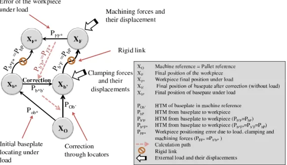
For the computation, the mechanical model needs the initial values such as the positions and orientations of the locators and clamps, their stiffness matrices and mass matrix of the baseplate, magnitudes and location of external forces and moments etc., as input data. Lagrangian formulation (eq. 7) is used to calculate the mechanical behavior of the fixturing system considering small displacements. The reference transformation of the mechanical model is shown in figure 8 where, PF F∗ = Pb∗b′ is the displacement of the workpiece-baseplate assembly under load. Once this displacement is known, The workpiece can be reoriented as detailed in the previous section.
∂ ∂t ∂(T − U ) ∂ ˙qi ! −∂(T − U ) ∂qi = ∂W ∂qi (7)
Figure 8: Transformation of reference axes for mechanical model
3.1
Energy calculation
Total energy of a system is composed of its potential and kinetic energies. Kinetic energy is negligible for the locators due to their negligible mass while potential energy of all locators can be calculated using equation 8.
U = 1 2
X
{∆X}Ti[K]i{∆X}i (8)
where, [K]i is the stiffness matrix of ith locator and ∆Xi is the relative
dis-placement vector of the contact point of that locator relative its other ex-tremity. Total kinetic energy of workpiece-baseplate assembly, consisting of translational and rotational kinetic energy [33], can be calculated by equation 9. T = 1 2{~V } T [M ]{~V } + 1 2{~Ω} T [I]{~Ω} (9)
where, {~V } and {~Ω} are the translational and rotational velocities respectively, while [M ] and [I] are mass and inertia matrices. Kinetic energy terms can be neglected for this specific case.
3.2
Clamping forces
Clamp is the means of tightening the workpiece on the fixture once it is located. As the locators are assumed to be elastic, the clamping force causes the locators to compress. Here, it is to be noted that if the initial position of the workpiece is measured through CMM, the deformation of the locators due to the load of the baseplate-workpiece assembly is already taken into account, so only the external forces will cause further deformation. Normally, the clamp is brought in contact with the baseplate and then it is tightened. Instead of measuring the magnitude of clamping force exerted by each clamp, the amount of distance at which the external end of the clamp is moved, is used to model the clamp. The clamp is taken as elastic element; a part of the external dis-placement will be transferred to the other end of the clamp (baseplate-clamp contact) while the rest will induce potential energy in the clamp. Here, trans-formed displacement vectors ({∆X}C,i) are calculated for each clamp as the
functions of workpiece displacement vector {∆XP, ∆YP, ∆ZP, ∆β, ∆γ, ∆α}T.
The total potential energy contained in all the clamps can be calculated using equation 10. UC = 1 2 X {∆X}T
C,i[K]C,i{∆X}C,i (10)
3.3
Machining forces
Clamps behave like static forces while the machining force changes contin-uously with time which makes it very difficult to compensate. At the moment,
the proposed mechanical model cannot compensate the machining forces in real time but in processes such as drilling, boring, assembling etc., it is rel-atively practical. In drilling, for example, a force acts at the center of the hole along with a moment couple. A generalized equation is proposed for total work done caused by external forces and moments in equation11, where, {F } is the applied force vector, {T} is the external torque vector, {∆XP} is the
displacement of point P of the baseplate under applied load, while {∆Θ} is the angular displacement due to applied torque. If an external force is acting away from the center of gravity, it will cause linear displacement as well as angular displacement of the workpiece; in that case, a HTM is used with the vector {∆XP} which adds the angular displacements to the work done by the
force. The generalized equation for the work done can be written as,
W =X
{F }i.{∆XP} +
X
{T}i.{∆Θ} (11)
Here, it is important to note that clamping force is the potential energy con-tained in clamps, so they have to be used on the right hand side of Lagrangian equation (eq. 7) with potential energy, while machining forces and load are external forces, so they have to be used on the left hand side of the Lagrangian equation (eq. 7).
3.4
Case study
A case study is performed on the fixturing system to explain the working and findings of the proposed mechanical model. A fixturing system, having six locators and two clamps, considered as three dimensional springs, is shown in figure 9. {F } is taken as machining force at any point on the workpiece, {T} is the moment of cutting tool, [KE]1 and [KE]2 are the stiffness matrices
Figure 9: Representation of the fixturing system as spring mass system
of clamps, {XE}1 and {XE}2 are the external displacements of clamps and
[K]1, [K]2, ...[K]6 are the stiffness matrices of the locators.
3.4.1 Data input
For data input, all locators are considered to have the same stiffness matrix with the length being only influencing parameter. Position of each locator is shown in figure10to calculate the transformed displacement for the potential energy calculation. The position of each locator’s contact point is written in table 5 where, Xp, Yp and Zp are the positions of point “P ” while Xi, Yi
and Zi are the positions of point “i” in x, y and z directions respectively with
i=1,2,...6. Stiffness matrix for first locator, as well as mass and inertia matrices for the baseplate are taken as,
[K]i = kr 0 0 0 kr 0 0 0 ka , [M ] = m 0 0 0 m 0 0 0 m [I] = 65 48mL 2 0 0 0 65 48mL 2 0 0 0 8 3mL 2
where, kr is the radial stiffness of the locator which is the sum of share and
bending stiffness placed in series, while, ka is the axial stiffness of the locator.
Table 5: Positions of each locator with respect to the center point P (mm) Locator Xp− Xi Yp− Yi Zp− Zi 1 L -L L/4 2 -L -L L/4 3 0 L L/4 4 L 2L 0 5 -L 2L 0 6 2L 0 0
Table 6: Positions of each clamp with respect to the center point P(mm) Clamp no. Xp− XC Yp− YC Zp− ZC
1 0 -2L -L/4
2 -2L 0 -L/4
locator model for this case study. Stiffness matrix of each locator is trans-formed depending upon their orientations with respect to the first locator. ka
remains unvaried with the advancement of locator while kr will change by the
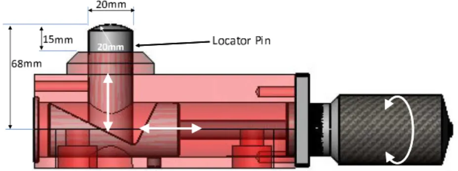
length of the locator projected out of the support (fig. 11). In our case, the projected length of locator, out of the support, is taken 15mm for all locators.
Figure 11: Screw-nut controlled wedge-slope Locator system
Here, the workpiece is assumed to be small so that its mass can be neglected as compared to that of the baseplate. The baseplate is chosen to be made of steel with a density of 7850kg/m3, the volume can be derived from figure 10
to calculate mass of the baseplate. The values for each variable are,
kr = 7.44 × 10⁸N/m , ka = 9.24 × 10⁸N/m
L = 60mm , m = 13.56kg
For the calculation of clamps’ potential energies, the positions of clamps are shown in table6. Clamps are supposed to be having unidirectional stiffness
(kE1 = kE2 = 9 × 10⁷ N/m) and displacement of both clamps are taken as
XE1 = XE2 = −0.025mm. Both the clamps are supposed to be inclined at 45
degree angles. The external displacement vectors for both clamps become,
{X}E1 = 0 −1.77 −1.77 × 10⁻⁵ m {X}E2 = −1.77 0 −1.77 × 10⁻⁵ m
The algorithm calculates the energy contained by clamps from the applied external displacement. For this specific example, a drilling operation is chosen for which F is 74N vertically downward and moment couple is -0.8 N-m for a hole diameter of 5 mm [34]. The force is acting at x = −0.1m and y = −0.1m from point P . The weight of the baseplate is also assumed to be acting at point P .
3.4.2 Results
Total potential energy is the sum of potential energies of all the locators and clamps. The mass and stiffness matrices of the system are obtained from calculation carried out in Mathematicar. The final stiffness matrix of the
[K] = 101.4 0 0 0 0.14 0 0 193.8 0 −0.14 0 0 0 0 295.2 6.6 −1.08 0 0 −0.14 6.6 1.13 0 0 0.14 0 −1.1 0 0.8 0 0 0 0 0 0 0.66 ×10⁷ (12)
The above calculation is carried out considering only locators’ body stiffness and it gives overestimated values. In fact, contact stiffness between spherical locator surface and baseplate surface is smaller than that of locator bodies. As this stiffness is in series with the body stiffness, total system stiffness will be reduced. An iterative process is carried out to calculate the non-linear contact stiffness of each locator and their deformations. The overall stiffness of the system, calculated as the result of locators’ body and contact stiffness, is shown in equation 13. [K] = 14.89 0 0 0 0.14 0 0 19.43 0 −0.14 0 0 0 0 31.48 1.52 −1.22 0 0 −0.14 1.52 0.18 −0.01 0 0.14 0 −1.22 −0.01 0.17 0 0 0 0 0 0 0.04 ×10⁷ (13)
Here, it is to be noted that during the calculations, the baseplate rotates due to compliance of the springs, so the terms with angles appear in mass matrix calculation. These terms can be neglected as the displacements are assumed to be small. Lagrangian formulation calculates the workpiece displacement vector. The calculated final (linear and angular) displacements are shown in table 7(a) and the advancements of each locator, required to compensate the displacement of workpiece-baseplate assembly, are shown in table7(b). These
advancements are calculated through the proposed kinematic model.
Table 7: Displacements under static mean load (a) Displacement of baseplate
Parameter Displacement ∆xP -10.47 µm ∆yP -7.98 µm ∆zp -5.29 µm ∆β -47.36 µrad ∆γ 61.98 µrad ∆α 0.67 µrad
(b) Advancements of all the locator
Locator Advancement (mm) 1 -0.01 2 -0.01 3 0.00 4 0.01 5 0.02 6 0.00 [M ]−1 [K] − ω2[I] = 0 (14)
The vibrational modes can be found by solving the equation14as in [35]. The calculated natural frequencies for this example, taking contact stiffness into account are, ω = 6803.37 5016.14 3780.59 3306.74 2163.96 1698.23 rad/sec
3.4.3 Results analysis
From the above results, it is observed that the system is most rigid in z direction (3 locators & 2 clamps) and least rigid in x direction (1 locator & 1 clamp), also angle α is negligibly small as only external couple of -0.8 N-m affecting it. The result validates the N-mechanical N-model for the exaN-mple. The mechanical model can be applied to more complex problems with multi-ple loads, multimulti-ple directional stiffness and different locations of clamps and locators. Also a huge difference of the stiffness of the fixturing system, by in-clusion of locators’ contact stiffness, is noticed. Therefore, the effect of contact stiffness on the precision of the workpiece cannot be neglected.
Natural frequencies of the system are calculated for static mean load. The speed of the spindle has to steer clear from these resonance frequencies for safe machining operation. External displacement of the clamps is increased from 0.025mm to 0.05mm and it is noted that the first resonance is shifted from 1698 rad/sec to 2725 rad/sec. This proves that the machine’s safe operating frequency can be changed by tightening or loosing the clamps.
4
Conclusion and Perspectives
In this article, an analytical model for the machining fixture is demon-strated. A baseplate is placed in between the machine table and the workpiece to avoid the irregular contact of the workpiece and the locators. Stepwise development is performed starting from the kinematic model in which the workpiece is rigidly fixed on the baseplate. The baseplate is located through a 3-2-1 locating configuration and all the elements of the fixture are consid-ered to be rigid. The kinematic model calculated the locators’ advancements which enabled us to relocate the workpiece indirectly by baseplate relocation.
Then in the mechanical model, the locators are assumed to be elastic and the baseplate is taken as the rigid mass element. The mechanical behavior of the fixturing system is calculated considering the body and contact stiffness of all the locators, stiffness and external displacements of clamps and machining forces. A case study is performed on a fixturing system in which a workpiece displacement vector is obtained due to the deformation of the elastic elements under external load. The advancement of each locator is also calculated to compensate this displacement. This model is also valid for more complex sys-tems with multiple clamps, multi-directional stiffness and multiple external forces and moments.
The repositioning system has not yet been designed to compensate very fluctuating forces due to machining process: chosen actuators are not fast enough. To achieve this function in order to adjust the workpiece position following high accuracy, piezoactuators could be inserted between workpiece and baseplate for active compensation.
5
Acknowledgements
The authors gratefully acknowledge the financial support from Higher Ed-ucation Commission (HEC), Pakistan.
6
Nomenclature
[Pij] : Transformation matrix form i to j
x′
i, y
′
i, z
′
i : Final position of ith locator in machine coordinate
a′
i, b
′
i, c
′
i : Unit vectors of calculated final planes of baseplate
D′
i : Vertical distance of each plane from origin
βi, βf : Initial and final angle along x-axis
γi, γf : Initial and final angle along y-axis
αi, αf : Initial and final angle along z-axis
xP, xF : Initial and final x-coordinate of point P of the workpiece
yP, yF : Initial and final y-coordinate of point P of the workpiece
zP, zF : Initial and final z-coordinate of point P of the workpiece
dzi, dyj, dx6 : Precision of locators’ axial positions i = 1, 2, 3, j = 4, 5
δXP, δYP, δZP : Uncertainty of workpiece-baseplate position
δβ, δγ, δα : Uncertainty of workpiece-baseplate orientation
[K]i, {X}i : Stiffness matrix and displacement vector of ith locator
[M ], [I], : Mass & inertia matrices of the baseplate {V }, {Ω} : Linear & angular velocity of the baseplate
[K]c,i, {X}c,i : Stiffness matrix and displacement vector of ith clamp
{F }i,{T} : ith Force and moment vectors vectors
{∆XP}, {∆Θ} : Virtual linear and angular displacements due to force
and moment
{XF,T}i : Transformed moment are for ith force
[K]Ei, {X}Ei : Stiffness and external applied displacement of ithclamp
∆XP, ∆YP, ∆ZP : Linear displacement of workpiece-baseplate assembly
under load
∆β, ∆γ, ∆α : Angular displacement of workpiece-baseplate assembly under load
References
[1] M. Ryll, T. N. Papastathis, and S. Ratchev, “Towards an intelligent fix-turing system with rapid reconfiguration and part positioning,” Journal of Materials Processing Technology, vol. 201, pp. 198 – 203, 2008. 10th International Conference on Advances in Materials and Processing Tech-nologies - AMPT 2007.
[2] X. Kang and Q. Peng, “Computer-Aided fixture planning: A review,” in ASME 2008 International Design Engineering Technical Conference, (New York), 2008.
[3] J. Cecil, “Computer-Aided fixture design - a review and future trends,” The International Journal of Advanced Manufacturing Technol-ogy, vol. 18, no. 11, pp. 790–793, 2001.
[4] Y. Kang, Y. Rong, and J. A. Yang, “Geometric and kinetic model based Computer-Aided fixture design verification,” Journal of Computing and Information Science in Engineering, vol. 3, no. 3, pp. 187–199, 2003. [5] H. Wang, Y. K. Rong, H. Li, and P. Shaun, “Computer aided fixture
design: Recent research and trends,” Computer-Aided Design, vol. 42, no. 12, pp. 1085–1094, 2010.
[6] I. Boyle, Y. Rong, and D. Brown, “A review and analysis of cur-rent computer-aided fixture design approaches,” Robotics and Computer-Integrated Manufacturing, vol. 27, no. 1, p. 1–12, 2011.
[7] S. Somashekar R., “Fixturing features selection in feature-based systems,” Computers in Industry, vol. 48, pp. 99–108, June 2002.
[8] R. J. Menassa and W. R. Devries, “Optimization methods applied to selecting support positions in fixture design,” Journal of engineering for industry, vol. 113, no. 4, 1991.
[9] U. Roy and J. Liao, “Fixturing analysis for stability consideration in an automated fixture design system,” Journal of Manufacturing Science and Engineering, vol. 124, pp. 98–104, Feb. 2002.
[10] B. Li and S. N. Melkote, “Improved workpiece location accuracy through fixture layout optimization,” International Journal of Machine Tools and Manufacture, vol. 39, no. 6, pp. 871 – 883, 1999.
[11] T. Aoyama and Y. Kakinuma, “Development of fixture devices for thin and compliant workpieces,” CIRP Annals - Manufacturing Technology, vol. 54, no. 1, pp. 325 – 328, 2005.
[12] A. Clement and P. Bourdet, “A study of Optimal-Criteria identification based on the Small-Displacement screw model,” CIRP Annals - Manu-facturing Technology, vol. 37, no. 1, pp. 503–506, 1988.
[13] P. Bourdet, “Logiciels des machines à mesurer tridimensionnelles,” Tech-niques de l’ingénieur. Mesures et contrôle, no. R1316, p. R1316–1, 1999. [14] F. Villeneuve, O. Legoff, and Y. Landon, “Tolerancing for
manufactur-ing: a three-dimensional model,” International Journal of Production Re-search, vol. 39, no. 8, p. 1625–1648, 2001.
[15] J. Asante, “A small displacement torsor model for tolerance analysis in a workpiece-fixture assembly,” Proceedings of the Institution of Mechanical Engineers, Part B: Journal of Engineering Manufacture, vol. 223, no. 8, pp. 1005–1020, 2009.
[16] B. Li, S. N. Melkote, and S. Y. Liang, “Analysis of reactions and minimum clamping force for machining fixtures with large contact areas,” The Inter-national Journal of Advanced Manufacturing Technology, vol. 16, pp. 79– 84, Feb. 2000.
[17] B. Li and S. N. Melkote, “Fixture clamping force optimisation and its impact on workpiece location accuracy,” The International Journal of Advanced Manufacturing Technology, vol. 17, pp. 104–113, Jan. 2001. [18] H. Deng and S. N. Melkote, “Determination of minimum clamping forces
for dynamically stable fixturing,” International Journal of Machine Tools and Manufacture, vol. 46, pp. 847–857, June 2006.
[19] S. Jayaram, B. El-Khasawneh, D. Beutel, and M. Merchant, “A fast ana-lytical method to compute optimum stiffness of fixturing locators,” CIRP Annals - Manufacturing Technology, vol. 49, no. 1, pp. 317 – 320, 2000. [20] A. Raghu and S. Melkote, “Modeling of workpiece location error due to
fix-ture geometric error and fixfix-ture-workpiece compliance,” Journal of man-ufacturing science and engineering, vol. 127, p. 75, 2005.
[21] A. Raghu and S. N. Melkote, “Analysis of the effects of fixture clamping sequence on part location errors,” International Journal of Machine Tools and Manufacture, vol. 44, pp. 373–382, Mar. 2004.
[22] Y. Lin and Y. Shen, A Generic Kinematic Error Model for Machine Tools. Citeseer, 2000.
[23] B. K. Jha and A. Kumar, “Analysis of geometric errors associated with five-axis machining centre in improving the quality of cam profile,” Inter-national Journal of Machine Tools and Manufacture, vol. 43, pp. 629–636, May 2003.
[24] X. Wan, C. Xiong, C. Zhao, and X. Wang, “A unified framework of er-ror evaluation and adjustment in machining,” International Journal of Machine Tools and Manufacture, vol. 48, pp. 1198–1210, Sept. 2008. [25] P. Martin, J. Dantan, and A. D’Acunto, “Virtual manufacturing:
predic-tion of work piece geometric quality by considering machine and set-up accuracy,” International Journal of Computer Integrated Manufacturing, vol. 24, no. 7, p. 610–626, 2011.
[26] S. Zhu, G. Ding, S. Qin, J. Lei, L. Zhuang, and K. Yan, “Integrated geo-metric error modeling, identification and compensation of CNC machine tools,” International Journal of Machine Tools and Manufacture, vol. 52, pp. 24–29, Jan. 2012.
[27] R. Ramesh, M. A. Mannan, and A. N. Poo, “Error compensation in machine tools – a review: Part i: geometric, cutting-force induced and fixture-dependent errors,” International Journal of Machine Tools and Manufacture, vol. 40, no. 9, pp. 1235–1256, 2000.
[28] C. Raksiri and M. Parnichkun, “Geometric and force errors compensation in a 3-axis CNC milling machine,” International Journal of Machine Tools and Manufacture, vol. 44, no. 12-13, p. 1283–1291, 2004.
[29] zimmer, “zimmer hip prosthesis, CPT 12/14 cemented stems.” http://www.zimmer.co.uk/web/enUS/pdf/product_brochures/
CPT_12_14_Hip_System_97-8114-01_rev_1.pdf, Sept. 2011.
[30] O. Rosenberg, V. Vozny, C. Sokhan, J. Gawlik, A. G. Mamalis, and D. J. Kim, “Trends and developments in the manufacturing of hip joints: an overview,” The International Journal of Advanced Manufacturing Tech-nology, vol. 27, no. 5, p. 537–542, 2006.
[31] M. Dietrich and K. R. Skalski, “Designing and manufac turing of cus-tomized human bone endoprostheses,” in The Eleventh World Congress in Mechanism and Machine Science, pp. 92–95, 2004.
[32] G. Halevi and R. Weill, Principles of Process Planning: a Logical ap-proach. Chapman and Hall, London, 1995.
[33] M. Lalanne, P. Berthier, and J. Der Hagopian, Mécanique des vibrations linéaires (avec exercices corrigés et programmes de calcul). Paris: Masson, 1986.
[34] G. C. Onwubolu and S. Kumar, “Response surface methodology-based approach to CNC drilling operations,” Journal of Materials Processing Technology, vol. 171, pp. 41–47, Jan. 2006.
[35] S. G. Kelly, Schaum’s outline of Theory and Problems of Mechanical Vi-brations. McGraw Hills, 1996.

![Figure 9: Representation of the fixturing system as spring mass system of clamps, {X E } 1 and {X E } 2 are the external displacements of clamps and [K] 1 , [K] 2 , ...[K] 6 are the stiffness matrices of the locators.](https://thumb-eu.123doks.com/thumbv2/123doknet/7391277.216455/23.892.201.691.149.438/figure-representation-fixturing-external-displacements-stiffness-matrices-locators.webp)