Science Arts & Métiers (SAM)
is an open access repository that collects the work of Arts et Métiers Institute of Technology researchers and makes it freely available over the web where possible.
This is an author-deposited version published in: https://sam.ensam.eu Handle ID: .http://hdl.handle.net/10985/8777
To cite this version :
Nejah JEMAL, Sandra ZIMMER-CHEVRET, Laurent LANGLOIS, Gabriel ABBA - Study of the forces generated during nonlinear friction stir welding: circular trajectory - Key Engineering Materials - Vol. 554-557, n°The Current State-of-the-Art on Material Forming, p.1007-1013 - 2013
Any correspondence concerning this service should be sent to the repository Administrator : [email protected]
Study of the forces generated during nonlinear friction stir welding:
circular trajectory
Nejah JEMAL
1,a, Sandra CHEV
RET
2,b, Laurent LANGLOIS
1,cand Gabriel ABBA
1,d1
LCFC, Laboratoire de Conception, Fabrication et Commande-Arts et Métiers ParisTech Metz.
2
Institut de soudure, Centre FSW, 2-4 Rue Pilâtre de Rozier, 57420 GOIN.
a
[email protected], [email protected], [email protected]
d
[email protected] Keywords: FSW, circular trajectory, longitudinal and traversal forces.
Abstract. Friction stir welding is known for his capability to achieve a linear weld. However, more investigation on a curved friction stir weld trajectory is still required to industrialize this promising process. In the same perspective, this study is aimed at analyzing the influence of nonlinear tool trajectory in friction stir welding. The study considers a variety of circular trajectories on the plane plate and uses them for experimentation while considering different welding parameters of rotation speed feed speed, axial force and tilt angle.
In FSW, the tool is generally needed to be tilted with a constant angle in the travel direction during welding process. Therefore, for circular trajectory, an adequate roll and pitch angle are assigned to the spindle in all tool positions. The paper presents the effect of circular trajectory on longitudinal and transversal forces generated during circular welding. The results are then compared with the experimental results which are obtained using linear FSW. Furthermore, the experimental investigation includes relationship between tool trajectory and weld quality.
Introduction
Friction stir welding (FSW) is a relatively new welding technique considered as a mechanical welding process. In fact, FS weld is obtained by the mechanical action of the tool on the workpiece. Metal will be stirred in the solid phase below the melting point of the metals [1].In consequence, this process can weld a large variety of material such as precipitation hardened aluminium alloys and ovoid hot cracking.
During FSW, a non-consumable rotating tool moves along a joint between two plates to be joined. This combined movement impose plastic deformation and stirring material in a required temperature. Both friction and deformation dissipation ensure workpiece’s heat elevation without reaching it melting point. FS weld quality is controlled by several process parameters, especially rotation speed, travel speed, forging force, welding angle and plunge depth.
Since FSW invention in 1991 [1], many researchers were interested in the physical phenomena to understand weld formation. Physical phenomena were generated by a combined interaction of process parameters. Those interactive effects make this task difficult.
Others researchers were interested in engineering process. They have presented several new techniques such as bobbin tool, FSW assisted by laser and control design process parameters to perform the friction stir welding. For straight weld, the welding force control has proved his efficacy to obtain good weld quality. The control of other input parameters is also desired. In fact, the deviations of some of parameters can cause a negative effect on the weld.
Recently, friction stir process is being widely used in many industrial sectors with the need of more and more complex shapes and configurations. However, in non rectilinear welding, it is difficult to maintain all welding parameters in appropriate permissible ranges [2,3].
Any deviation of the tool position, tool orientation, and process speed parameters can produce defects on weld like excess of flash, which increases the need of analyzing generated forces and welding parameters in different welding configurations especially for curved trajectory [4,5].
The purpose of this work is to analyze forces generated in curvilinear weld. The influence of the curved trajectory on weld quality will be presented by examining flash formation with different process parameters.
Motivation and method
FSW have very interesting advantages that make it attractive to be used in many industrial applications. Its welding capability motivated the welding community for robotize FSW which offer flexibility to the process. In fact, complex welding trajectory can be realized in a single configuration which reduces cycle time. However, this can not be adequately achieved without a suitable FSW machine control design which needs an acceptable force model, to compensate any machine deviation during the process.
The generation of transverse efforts during FSW can deviate tool trajectory. So, it is necessary to model the mechanical force for designing control laws for robotized FSW. In straight welding, generated forces can be considered as constant during the welding phase. For curved FSW, this constant force hypothesis is not available because heat distribution and material flow around the tool is more complex. Therefore, empirical forces model proved on straight line weld cannot be applied on curvilinear FSW.
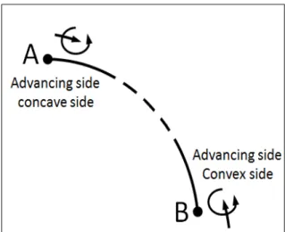
In FSW, the weld is not symmetrical; rotation and travel direction generate two sides on weld (the advancing side and retreating side). The advancing side on which the rotation direction is the same as the tool travel direction. The opposite side is called retreating side.
Figure. 1. Two possible configurations of welding portion A-B.
For welding a curved joint, the change of one of the speed direction (rotation or travel) make changing the advancing side from concave side of the curve to his convex side. With this alternative, we can change flash position which can be benefit for some application. In fact, flash position can create a fatigue crack initiation [6] then we can anticipate fracture position.
For this study, we choose to weld two circular trajectories with different radii (125mm and 75mm) in the same test plate. The welding cycle begins with the bigger circle followed by the smaller one. We provide a cooling plate between the two welding phases. Those welding sequences and radii are chosen to avoid the heat elevation of the workpiece. Material used for this test plate was 6081-T361 with a square dimension of a 330 mm with a 6 mm thickness.
FSW was performed using five-axis MTS machine which is flexible and mechanically robust at the same time. The machine has a capability to weld a complex geometry with a forging force control. Thanks to its gantry structure, we have a large working area which is adaptable for welding long products like aluminium panels.
Fig. 2 shows FSW set up used for clamping workpiece and illustrate FSW machine axes. To ensure the test repeatability; test plate is placed at the same reference related to the machine table in all experiment. After positioning test plate on the defined reference, we use clamps to hold the
workpiece against the backing bar, thus avoiding relative movement of the test plate with the baking bar in all welding phases.
Figure. 2. Experiment set up used for circular welding.
To study the influence of welding conditions, experiment tests are realized with different input process parameters. The table 1 details all different experiment: here we chose two welding configurations based on changing travel speed direction. Our experiments were carried out with the combination of variations of rotation speeds, travel or welding speeds and welding angles. Where welding angle is angle is defined as the angle between the tool axis and the local surface normal to the welding direction.
Table. 1. Experimental welding conditions. Test conditions N [rpm] Va [mm/min] Fz [kN] Welding angle[°] Radius [mm] Advancing side localization Test 1-1 1100 450 10 3.5 125-75 ADV-INT Test 2-1 1100 650 10 3.5 125-75 ADV-INT Test 3-1 900 450 10 3.5 125-75 ADV-INT Test 4-1 1100 450 10 2.5 125-75 ADV-INT Test 5-1 1100 650 10 2.5 125-75 ADV-INT Test 6-1 900 450 10 2.5 125-75 ADV-INT Test 7-1 1100 450 10 3.5 125-75 ADV-INT Test 8-1 1100 650 10 3.5 125-75 ADV-EXT Test 9-1 900 450 10 3.5 125-75 ADV-EXT Results and discussion
As the tool moves along the circular trajectory, we observe that tool orientation changes needs to be adapted with the tilt imposed angle. Roll and pitch standard machine angles will be regulated to obtain the desired tilt tool angle during welding operation. Fig. 3 shows tool orientation evolution during circular welding.
Forces generated during FSW can be represented in two different coordinate systems. The first is a global reference relative to the machine. The second reference is relative to coordinate system related to the tool.
In Fig. 3 Fx(tool) and Fy(tool) are presented on a reference related to the tool. The projection of these two forces in machine frame of reference is mentioned by Fx(word) and Fy(word).
Where Fx(tool) is defined as the force needed to move the tool along the welding trajectory and
Fy(tool) is the force measured in the traverse direction and it is caused by the asymmetric pressure
around the FSW tool.
Figure. 3. Evolution of Fx(tool), Fy(tool) ,Fz(tool), roll and pitch during FSW.
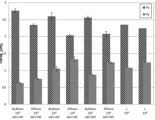
For experiment test 2-1, 5-1 and 8-1, which have the same speed parameters, we calculate the mean value of Fx(tool) and Fy(tool) for the welding phase. In Fig. 4, we have reported the average of those forces applied by the FSW tool for different experimental parameters.
Comparison of the forces generated in linear and circular welding proves that Fx(tool) and Fy(tool) are depending on trajectory.
At similar welding conditions, Fx(tool) generated by the welding of the first circle R=125 mm is more important than that generated during the welding of the second circle. The force Fy (tool) increases when welding passes from smaller radius circle to the bigger one.
We observe in Fig.3, that generated forces change during the welding phase. This result can be explained with different reasons. It may be related with the temperature distribution and thermal exchange due to the distance of the weld to the border of test plate. This may also due to the non similar clamping at each welding zone.
Figure 4. Average forces measured in different input process. The norm of the force applied by the tool to the workpiece can be calculated as follows:
(1) This calculation indicates that the norm force tool is higher when welding bigger radius of curvature trajectory. This result can be explained by the heat distribution that favors more temperature elevation in welding zone for smaller radii trajectory. Compared to the straight weld forces, we note that Fx(tool) on circular trajectory is more important, while Fy(tool) is reduced on circular trajectory.
Fig. 4 shows the influence of the welding angle on forces generated. The same influence of this parameter was observed on circular and linear trajectories. We note that when we increase the welding angle from 2.5° to 3.5°, the travel force Fx(tool) will rise up whereas the transverse force
Fy(tool) decrease.
The superficial appearance of circular welds for different tests is compared by using Table 2. This table shows weld surfaces achieved with various input parameters.
Table. 2. The superficial appearance of circular weld with different welding parameters.
Welding
parameters Condition 1 Conditions 2 Conditions 3
Va[mm/min] 450 650 450
N [rpm] 1100 1100 900
FZ [kN] 10 10 10
Test Test 1-1 Test 2-1 Test 3-1
Welding angle [o] 3.5
Advancing Side Interior
Test Test 4-1 Test 5-1 Test 6-1
Figures
Welding angle [o] 2.5
Advancing Side Interior
Test Test 7-1 Test 8-1 Test 9-1
Figures
Welding angle [o] 3.5
Advancing Side exterior
Summary of Table 2 shows that welds obtained with 2.5° tilt angle present more excessive flash than welded by 3.5°.
For welds obtained with an exterior advancing side, the flash formation always remains on the retreating side, but it can be observed that there is a d difference in the nature of flash formation. Flash observed with an interior advancing side seems slightly less but have more discontinuity aspect. This discontinuity flash makes its removal difficult during and after welding. For example, for the test 2-1, the flash is cut with the tool movement, but it is still attached to the weld in test 8.1. For the same welding parameters, it appears that flash obtained with the small circle is lesser than the bigger circle.
Here, more flash is obtained when we increase the tool rotation speed from 900 rmp to 1100 rpm. Flash will be reduced however if the travel speed is increased from 450 mm/min to 650 mm/min. In fact, when we decrease the welding temperature with increasing travel speed or decreasing rotation tool speed, the tool will be more plunged to achieve the desired forging force, so we will obtained more flash formation. For these speed process ranges, it is clear that the travel speed variation have more influence on the flash formation which in relation with the heat input per unit length.
In relation with analyzed forces, we can deduce that flash formation is associated with transverse force. When the Fy(tool) increases, the flash formation intensifies.
Conclusion
The analysis of the experimental data has proved that forces applied to the tool on curved joint are different from those obtained on straight linear welding. It proves that variation of the tool trajectory affects the welding quality. The shape and the size of the flash can differ when we change trajectory curvature. Flash can be reduced by choosing the right welding parameters.
It has been observed that generated forces in FSW are related to the velocity direction parameters and the radii of the curvature trajectory.
For the future, we can exploit the temperature distribution to explain generated forces with different circular welding parameters.
Acknowledgements
The authors would like to thank “Institut de Soudure” for their contribution in conducting experiments work. They also want to thank R. Boutron for his technical assistance.
References
[1] R.S. Mishra, Z.Y. Ma, Friction Stir Welding and Processing Materials Science and Engineering, R50 (2005) 1-78.
[2] H. Takahara, M.Tsujikawa, S.W. Chung,Y. Okawa, S. Oki and K. Higashi, Optimum Processing and Tool Controls for Three-Dimensional Friction Stir Welding. Materials Transactions, Vol. 49, No. 8 (2008) 1911-1914.
[3] H. Takahara, M. Tsujikawa, S. W. Chung,Y. Okawa, S. Oki and K. Higashi, Optimization of Welding Condition for Nonlinear Friction Stir Welding. Materials Transactions, Vol. 49, No. 6 (2008) 1359 -1364.
[4] T.I. van Niekerk, T. Hua and D.G. Hattingh, Experimental Implementation of Complex Curvature Friction Stir Welding. R & D Journal of the South African Institution of Mechanical Engineering (2007) 23 (2).
[5] D. H. Lammlein, B. T. Gibson, D. R. DeLapp, C Cox, A M Strauss, and G E Cook, The friction stir welding of small-diameter pipe: an experimental and numerical proof of concept for automation and manufacturing. Proceedings of the Institution of Mechanical Engineers, Part B: Journal of Engineering Manufacture vol. 226 no. 3 (2012) 383-398.
[6] Y. Uematsu, K. Tokaji, H. Shibata, Y. Tozaki and T. Ohmune .Fatigue behaviour of friction stir welds without neither welding flash nor flaw in several aluminium alloys. Int. J. Fatigue, vol. 31, no10 (2009) 1443-1453.