HAL Id: hal-00931798
https://hal.inria.fr/hal-00931798
Submitted on 15 Jan 2014
HAL is a multi-disciplinary open access
archive for the deposit and dissemination of
sci-entific research documents, whether they are
pub-lished or not. The documents may come from
teaching and research institutions in France or
abroad, or from public or private research centers.
L’archive ouverte pluridisciplinaire HAL, est
destinée au dépôt et à la diffusion de documents
scientifiques de niveau recherche, publiés ou non,
émanant des établissements d’enseignement et de
recherche français ou étrangers, des laboratoires
publics ou privés.
Enhanced OSPF Graceful Restart
Carole Hounkonnou, Eric Fabre
To cite this version:
Carole Hounkonnou, Eric Fabre. Enhanced OSPF Graceful Restart. IFIP/IEEE International
Sym-posium on Integrated Network Management, May 2013, Ghent, Belgium. �hal-00931798�
Enhanced OSPF Graceful Restart
Carole Hounkonnou, Eric Fabre
INRIA Rennes - Bretagne Atlantique
Abstract—Modern OSPF (Open Shortest Path First) routers
can preserve their packet forwarding activity while they reboot. This enables maintenance operations in the control plane with minimum impact on the data plane, such as the Graceful Restart (GR) procedure. This of course assumes the stability of the network topology, since a rebooting router is unable to adapt its forwarding table and may cause routing loops. The Graceful Restart standard thus recommends to revert to a normal OSPF restart as soon as a topological change is advertised. This paper proposes to be less conservative and to take full advantage of the separation between the control and forwarding functions. This is achieved by new specific functionalities: (a) the prediction of routing loops caused by a restarting router, (b) the determination of the minimal number of temporary backup forwarding actions that should be applied to prevent these loops, without reverting back to a normal OSPF restart, and (c) the design of action plans to set and remove these temporary backups in order to avoid micro-loops when the restarting router goes back to a normal functioning. This results in minimal traffic perturbations when topology changes during a maintenance operation. [1] provides a longer version of this paper, including proofs.
Index Terms—OSPF, Graceful Restart, Network Maintenance.
I. INTRODUCTION
OSPF (Open Shortest Path First) [2], [3] is a widely used link state routing protocol in the Internet. Modern router architectures separate the data plane, and thus the forwarding function, from the control plane, that runs the routing protocols such as OSPF. This creates a possibility to keep forwarding packets while the control plane is being restarted. This so-called Graceful Restart procedure has been standardized [4] and is available in commercial routers [5], [6]. Graceful Restart requires the cooperation of all routers neighboring the restarting one. Their role is to keep up the adjacency with the restarting router as long as the topology remains static. In case of any change in the topology, one must immediately stop the graceful restart and return to the standard OSPF behavior, which thus fully removes the restarting router from the topology. This intends to avoid the possible creation of routing loops resulting in packet losses and unreachable destinations.
Such an abrupt change of behavior can be temporarily harmful to the network. And, strictly speaking, it may not be necessary: not every topological change will result into a routing loop, so the forwarding activity of the restarting router could be maintained. Furthermore, even if routing loops are created, they can be temporarily fixed. The present paper studies the possibility of such smoother changes of behavior. Since the standardization of the graceful restart procedure, few papers have examined its practical consequences. [7]
ex-amined how a general reboot of all routers could be organized, taking into account that a helper node cannot reboot until the node it is helping has completed its own reboot. To the best knowledge of the authors, however, the issue of preventing routing loops during the graceful restart of OSPF routers has only been tackled by Shaikh et al. in [8] and more recently in [9]. These contributions detail necessary conditions to the existence of routing loops, in the case of several restarting routers, and propose to remove the restarting routers from the forwarding path as soon as these conditions are detected. The present paper follows a similar approach for the detection, but relies on a necessary and sufficient condition for the existence of routing loops, in the case of a single restarting router. The developments then go further by proposing minimal temporary corrections to such loops, and by correcting simultaneously multiple problematic destinations. In our approach, when a routing loop is detected, only a few nodes are informed and apply a correction, rather than broadcasting a global warning to all nodes and returning to a standard OSPF behavior. As a result, the restarting router is maintained in the topology for all destinations to which it is not dangerous.
The paper is organized as follows. Section II illustrates the normal and graceful restarts of OSPF and explains how routing loops can occur during a graceful restart. Section III introduces the notions of source and destination graphs. These graphs are central for the detection of routing loops (Section IV). Section V characterizes the severity of such routing loops, using coloring properties of destination graphs. It then explains in detail how to correct such loops by temporary reroutings, in the case of a single problematic destination. Section VI extends the problem to several problematic destinations to correct simultaneously. Finally, Section VII evaluates, on a typical network topology, the proposed enhanced OSPF GR.
II. NORMAL ANDGRACEFULRESTARTS INOSPF OSPF runs on a simple abstract vision of the network: a weighted and directed graph (Fig. 1), that we call the
topological graph. At the core of the OSPF routing protocol
Fig. 1. An example of OSPF network
is a distributed, replicated link state database that describes the collection of routers in the domain, how they are inter-connected, and the quality of each link. So each node knows
the full topological graph at any time. Given the link state database, and assuming this is a reliable description of the network state, each node/router runs Dijkstra’s algorithm to derive the shortest paths to all other nodes. The shortest paths originating from (and calculated by) some router R organize as a shortest-paths tree (SPT) rooted at R that we call the source
graph for router R. Fig. 2 displays this source graph for node
C in the network of Fig. 1.
E C D F G B A 1 1 1 1 1 1
Fig. 2. Shortest paths from C to all destinations (the source graph of C). During a normal router restart, the neighbor routers break adjacency with the restarting one, i.e. they generate new LSAs that are flooded throughout the network and cause all routers to update their forwarding tables in order to avoid the rebooting node. A few minutes later, once the restart is completed, the neighbor routers re-establish adjacency with the rebooted one and the whole sequence of LSA floodings and forwarding tables updates is repeated.
With a graceful restart, a router, whose control plane is about to restart and whose forwarding plane functions normally, sends a grace LSA to its neighbors, declaring its intention to perform a graceful restart within a specified grace period. The neighbor nodes (known as helpers) continue to list the restarting router as fully adjacent in their LSAs during the grace period, but only if the network topology remains static. Once the control plane restarts, the restarting router goes through a normal adjacency establishment procedure with all the helpers, at the end of which the restarting router and the helpers regenerate their LSAs.
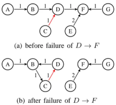
Any change in the network topology during the grace period would cause the helpers to abort the graceful restart and generate their LSAs showing the breakdown of adjacency with the restarting router. Indeed, the latter is unable to adjust its forwarding table in a timely manner when the network topology changes. Its forwarding table is said to be frozen. Since this table may no longer be consistent with the new network topology, routing loops can occur. Fig. 3 illustrates this routing loop creation for the network of Fig. 1, assuming link D→ F fails while node C is restarting.
A B D F G
C E
1 1 1 1
2 1
(a) before failure of D → F
A B D F G C E 1 1 1 1 2 1 (b) after failure of D → F
Fig. 3. Destination graphs to F before and after failure of link D → F .
To prevent such routing loops, [4] takes a conservative approach and recommends to revert to a normal OSPF restart when a change in the network topology occurs. However, not every topological change will result into a routing loop even if the restarting router is unable to adjust its forwarding table. This observation underlines the need for a solution able to detect beforehand the creation of loops while a graceful restart is in progress, and possibly to temporarily fix them, in order to avoid the burden of several complete OSPF reconvergences and possible perturbations in the load balancing.
III. PROPERTIES OFROUTINGGRAPHS
Definition 1. The topological graph of an OSPF network is
a weighted directed graph G = (V, E, w) where the finite set V denotes vertices (or ‘nodes’ or ‘routers’), E⊆ V × V \ {(v, v), v ∈ V } denotes the arcs (or ‘links’), and w : E → R+
is the weight (or cost) function on links. It is assumed that any node is reachable from any other in G (see below).
Definition 2. A path from u to v in G = (V, E, w) is a sequence of vertices p= (v0, v1, ..., vn) of V such that v0= u,
vn = v, and each (vi, vi+1) ∈ E for 0 ≤ i < n. When such
a path p exists from u to v, v is said to be reachable from u through p, denoted u v (or simply u v). v is calledp
descendant of u and u is called ancestor of v. A circuit in G is
a path such that u= v. The weight/cost of path p is the sum of the weights/costs of its arcs: w(p) = Pni=1w(vi−1, vi). The
distance between u and v is then d(u, v) = min{w(p) : u p v}, and a shortest path between u and v is a path reaching this bound.
We use two types of routing graphs in the sequel, source and destination graphs, attached to any node of G= (V, E, w).
Definition 3. A source graph Hσ = (V, E′) is a directed
graph such that every node has a unique predecessor for E′, except a unique node σ ∈ V (the source), which has none: ∀v ∈ V \ {σ}, |{u : (u, v) ∈ E′}| = 1 (and 0 for v = σ).
Hσ is said to be correct iff it contains no circuit. In G =
(V, E, w), the source graph Gσ ∗= (V, Eσ ∗) of a node σ ∈ V
is obtained by gathering consistent shortest paths from σ to all other nodes in G: Eσ ∗⊆ E, and ∀v ∈ V \ {σ} the unique
path p such that σ v in Gp σ ∗satisfies w(p) = d(σ, v) in G.
Definition 4. A destination graph Hδ= (V, E′) is a directed
graph such that every node has a unique successor for E′, except a unique node δ∈ V (the destination), which has none: ∀u ∈ V \ {δ}, |{v : (u, v) ∈ E′}| = 1 (and 0 for u = δ).
Hδ is said to be correct iff it contains no circuit. In G =
(V, E, w), the destination graph G∗
δ = (V, Eδ∗) of a node δ ∈
V is obtained by gathering consistent shortest paths to δ from all other nodes in G: Eδ∗⊆ E, and ∀u ∈ V \ {δ} the unique path p such that u δ in Gp ∗δ satisfies w(p) = d(u, δ) in G.
Source and destination graphs naturally appear in OSPF: by connecting the forwarding rules to destination δ in all nodes of topology G, one gets a destination graph Gδ. Ideally, each Gδ
up-to-date knowledge about G. However, during a graceful restart, the Gδ in use may differ from the expected G∗δ, due
to frozen forwarding tables, and thus may contain circuits. Similarly, one could build the source graphs Gσ actually used by OSPF for topology G: for each source σ, u is the unique predecessor of v if a packet originating from σ and addressed to v reaches it through u. Ideally again, Gσ should coincide
with Gσ ∗, but this may not hold during a graceful restart.
Observe that source and destination graphs are dual notions: inverting the orientation of edges in a source graph yields a destination graph.
As destination graphs encode the effective forwarding rules applied by OSPF, they are instrumental in the prediction of routing loops. These simple objects have numerous properties that can help for this task.
Definition 5. In a directed graph G= (V, E), the connected
to relation on vertices, denoted by u ∼ v, is defined as the equivalence relation on V generated by u v ⇒ u ∼ v (this amounts to dropping the orientation of edges). A connected
component of G is a subgraph G|V′ = (V′, E|V′×V′) of G
such that V′⊆ V is an equivalence class of vertices for ∼.
Proposition 6. Let Hδ be a destination graph, each connected
component of Hδ either contains δ or contains a unique
circuit. Therefore, if Hδ contains p circuits, then it contains
p+ 1 connected components.
See [1] for proofs. As an example, the destination graph GF
in Fig. 3(b) contains two connected components. All destina-tion graphs have a similar shape, with connected components made of a single circuit and directed trees descending towards it, plus one last tree directed toward the destination node.
Corollary 7. Let G∗δ = (V, Eδ∗) be the destination graph
gathering the shortest paths to δ in G = (V, E, w). Let Gδ
be a perturbed version of G∗δ where k nodes have modified their successor. Then Gδcontains at most k circuits, and k+1
connected components.
The perturbations above model the fact that k routers are not using the forwarding table they should follow on topology G, but rely on an outdated one. As a consequence, if the topology changes while k routers are operating a graceful restart, at most k routing loops can be created for each destination δ. And as shown in Section VI, the same loop can alter several destinations at a time. This suggests that few ‘problems’ should actually appear and require fixing.
IV. PREDICTION OF ROUTING LOOPS
Let G0 = (V, E0, w0) denote the topology with which a
restarting router r computed its last forwarding table, and let Grbe the source graph of node r in this topology. In Gr, node
r has h1, ..., hK as successors, which are also helper nodes by
design of the graceful restart procedure. Let Dr(hk) = {v :
hk v in Gr} denote the descendants of hk in Gr,1 ≤ k ≤
K. As Gr is a correct source graph, theDr(hk) ∪ {hk} form
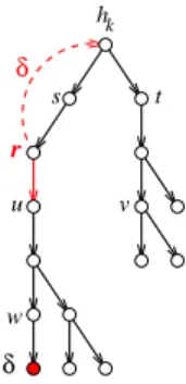
a partition of V \ {r}. r u v s t w δ h δ k
Fig. 4. The expected source graph Ghk of h
k, and its misbehavior for packets addressed to δ. Instead of correctly forwarding such packets to u, node r selects a wrong neighbor and actually send them back to hk, thus creating a circuit.
Let G1 = (V, E1, w1) denote the actual network topology.
We assume that the links(r, hk) ∈ E0 are still present in E1.
Let Ghk be the source graph of node h
kin this new topology,
for1 ≤ k ≤ K (Fig. 4). Let Dhk(r) = {v : r v in G
hk}
denote the descendants of r in Ghk (D
hk(r) contains u and
all nodes below u in Fig. 4).
Finally, for a node δ∈ V , let Gδ be the actual destination
graph to δ when all nodes use topology G1 except r that uses
topology G0.
Proposition 8. There exists a (unique) routing loop in the
destination graph Gδ iff there exists a (unique) k such that
δ∈ Dr(hk) ∩ Dhk(r).
This defines a simple practical test for discovering desti-nations δ at risk, i.e. unreachable due to the presence of a routing loop. All neighbors of r are advertised that r initiates a graceful restart, and they act as helpers, so they can store the frozen Grused by r all along the grace period. Each successor hk of r can then determine and announce the contents of
Dr(hk) ∩ Dhk(r) if the topology changes.
V. CORRECTION OF AROUTINGLOOP
Let Gδ = (V, Eδ) be a destination graph over topology
G= (V, E, w), so Eδ ⊆ E. If Gδ is correct (i.e. contains no
circuit), it can reliably be used to forward packets to δ, but it may not use the shortest paths of G. Assume that k routers r1, ..., rk∈ V are performing a graceful restart in G. As seen
above, the actual Gδ used for forwarding packets to δ differs
from the optimal G∗δ by at most k arcs: the arcs originating from routers r1, ..., rk (assuming they differ from δ) can point
to any node in V . Therefore Gδ contains at most k circuits,
that each contain at least one node of{r1, ..., rk}. Given that
these nodes cannot change their forwarding rule, is it possible to modify the routing choices of other nodes to turn Gδ into
a correct destination graph? What is the minimal number of nodes that should be rerouted, and where are they?
A. Severity Degree of Routing Loops
Definition 9. Let Gδ = (V, Eδ) and G′δ = (V, Eδ′) be two
destination graphs in G such that r has the same successor in Gδ and in G′δ. Let us denote by C(Gδ, G′δ) = |Eδ \ Eδ′| =
|E′
of node v in Gδ is defined as Cδ(v) = min{C(Gδ, G′δ) :
v δ in G′ δ}.
So Cδ(v) is the minimal number of reroutings that should
take place in Gδin order to correctly forward packets from v to
destination δ. Note that Cδ(v) can be infinite if no correction
is possible, and Cδ(v) = 0 iff v is in the connected component
of Gδ that contains δ.
Proposition 10. Let Gδ be a destination graph in topology
G. If u v in Gδ, then Cδ(u) ≤ Cδ(v). And if the arc (u, v)
exists in G, then Cδ(u) ≤ Cδ(v) + 1.
As a consequence, the color of nodes in each connected component of Gδ augments as one progresses towards the
circuit, and it is constant on this circuit. There cannot be gaps in series of colors: vertices of color n exist only if there exist vertices of color n− 1.
Corollary 11. Gδ contains a circuit which color is infinite iff
this routing loop cannot be corrected. The color of a circuit in
Gδ is the number of reroutings that is necessary to redirect to
δ all nodes of the connected component containing this circuit.
If Gδ contains a unique circuit, its color is the minimal (and
sufficient) number of reroutings to transform Gδ into a correct
destination graph.
Fig. 5 illustrates the vertex coloring on the destination graph GF, for our running example. Vertices E, F, G are
located in the same connected component as the destination F , therefore their color is 0 (displayed in green). One has CF(A) = 1 (yellow), because edge (A, E) exists in topology
G, and CF(E) = 0. A can easily reach F by rerouting packets
through E instead of B in GF. Finally, vertices B, C, D in
the circuit all have color 2 (red). C is the frozen restarting router, so it cannot be rerouted, and neither B nor D could be directly rerouted to E, F or G (recall that link(D, F ) failed). However, B can be rerouted to A, and the latter to E. These two modifications are sufficient to guarantee that all packets addressed to F actually reach it.
F G E A B D C 1 1 1 1 2 1
Fig. 5. Vertex colors on the destination graph GF: green=0, yellow=1, red=2. Proposition 10 reveals a simple coloring algorithm over Gδ.
Nodes of color0 are easily obtained by back-tracking from δ. For any remaining (uncolored) node u, if arc(u, v) exists in G and v has color 0, then u takes color1. And one can recover all nodes of color 1 on Gδ by backtracking from such u nodes.
Similarly, nodes of color 2 are the uncolored predecessors u in G of a node v of color 1, or the uncolored ancestors in Gδ
of such u nodes. And so on, until no more coloring rule is applicable. The remaining uncolored nodes take ∞ as color. This algorithm has a linear complexity, similar to Dijkstra’s algorithm, and it can also be distributed. It allows one to decide if routing loops can be corrected.
B. Correction of a Routing Loop
Due to space limitations, the remainder of the paper focuses on the case of a single restarting router in G. Therefore, if destination graph Gδ is incorrect, there is a single routing
loop to repair.
Corollary 12. Let the incorrect destination graph Gδ contain
a unique circuit p of color n. At least one node of this circuit (different from the frozen node r) can be rerouted to a node of color n− 1. Performing this rerouting yields the destination
graph G′δ that again contains a unique circuit p′, of color
n− 1.
This result derives simply again from Proposition 10. Its interest is to reveal a simple procedure to determine the n reroutings that can turn Gδ into a correct destination graph.
Fig. 6 illustrates these two steps for the GF in Fig. 5: B is
first rerouted from C to A, then A is rerouted from B to E.
F G E A B D C 1 1 1 1 2 1
(a) New vertex colors once B is rerouted from C to A. F G E A B D C 15 1 1 1 2 1
(b) New vertex colors once A is also rerouted from B to E.
Fig. 6. Successive reroutings to correct destination graph GF. In summary, when a topological change occurring during a (single) graceful restart creates a routing loop for some destination δ, a simple procedure can determine the minimal number n of reroutings that could correct it, and the location of these reroutings. There generally exist several such temporary ‘patches’ of n reroutings, and one could wonder which one is the most efficient in terms of average cost, if link weights are taken into account. We conjecture that this problem is NP hard. One may wonder about situations where the color of the circuit is infinite. In that case, there is no solution to reroute messages to δ around r. Therefore a standard restart of OSPF would also be useless to resolve the problem.
C. Scheduling of Backup Routings
Assume one has determined a sequence s1, ..., snof vertices
that should be rerouted to correct a destination graph Gδ,
where the index i in si represents the color Cδ(si). In which
ordering should these temporary reroutings be performed? One possibility is illustrated in Fig. 6, where s2 = B is rerouted
before s1= A in GF. The reverse order is illustrated in Fig. 7.
As one can notice, this second option offers a better transient mode: nodes are progressively rerouted correctly to δ = F , whereas in the previous option all nodes suffer from the loop until the last rerouting is performed.
F G E A B D C 15 1 1 1 2 1
(a) New vertex colors in GF once A is rerouted from B to E. F G E A B D C 15 1 1 1 2 1
(b) New vertex colors in GF once B is then rerouted from C to A.
Fig. 7. Successive reroutings to correct destination graph GF.
Proposition 13. Let s1, ..., sn be a minimal sequence of
ver-tices that should be rerouted to correct Gδ, where Cδ(si) = i
in Gδ, and n = Cδ(r). Rerouting only si to its appropriate
new successor yields G′δ where the new node colors satisfy
C′
δ(s) = Cδ(s) if Cδ(s) < i, and Cδ′(s) = Cδ(s) − 1 if
Cδ(s) ≥ i.
A consequence of this result is that one should start rerout-ing nodes in the order s1, ..., sn, in order to maximize the color
decrease in Gδ, i.e. to maximize at each step the number of
nodes that can correctly reach δ.
Assume now that the restarting router r has finished its graceful restart. Can it safely switch to its new forwarding table (corresponding to the actual topology G1)? And how
should one remove the temporary rerouting patches? Fig. 8 illustrates the return in function of r = C, now correctly connected to E, and a removal of the rerouting patches following order s1= A, s2= B. As one can notice, this may
recreate forwarding loops, whereas the converse ordering is safe. A similar phenemenon was already observed in standard OSPF convergence, and led to the developement of ordered updates of forwarding tables, known as OFIB [10]–[12].
F G E A B D C 15 1 1 1 2 1
(a) C recovers its normal routing to F through E in G′ δ. F G E C A B D 1 1 1 1 2 1
(b) Vertex colors once A recovers its normal route through B in G′
F. F G E A B D C 1 1 1 1 2 1
(c) Vertex colors once B then recovers its normal route through C in G′
F.
Fig. 8. Successive removals of the temporary reroutings into the corrected destination graph G′
F, after node C returns to function.
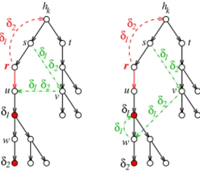
δ h r u v s t w r u v t s w k hk δ1 δ2 δ1δ2 1 δ δ2 δ2 δ1 δ2 δ1 1 δ δ1 δ2 2 δ δ1 δ1 2
Fig. 9. Rerouting packets addressed to δ1 with a minimal number of hops in order to go around r (and thus avoid the circuit). This rerouting path can also be (partly) used to correct the circuit on the path to δ2 when δ1 δ2 in GHk.
Proposition 14. Let s1, ..., sn be a minimal sequence of
vertices that have been rerouted to correct the loop created by r in Gδ, where Cδ(si) = i in Gδ, and n= Cδ(r). Once
r returns to function, it can safely switch to its expected
forwarding table without recreating a loop. And removing the temporary reroutings starting from sn to finish by s1
guarantees that no transient routing loop appears.
VI. CORRECTION OFMULTIPLEROUTINGLOOPS Assuming a single router r has a frozen forwarding table while the network topology evolves, we have shown how to detect a routing loop for some destination and how to correct it with minimal effort. This leaves open the burden of fixing
all problematic destinations, which we address now. The idea
is that fixing a problematic destination may help resolving others. Consider again the setting of Section IV, where all nodes established their forwarding table according to topology G1excepted node r, which used topology G0. We rely on the
criterion of Proposition 8.
Proposition 15. Let δ1, δ2 be two destinations in Dr(hk) ∩
Dhk(r) where hk is one of the successors of r in its source
graph Gr. Consider the source graph Ghk of node h
k (in
topology G1). If δ1 δ2 in Ghk, then the routing loop to δ1
and to δ2 goes through the same nodes. The node reroutings
that correct the destination graph Gδ1 can be used to correct
as well Gδ2 (see Fig. 9).
This also proves that the color Cδ2(r) of the routing loop (to
δ2) in Gδ2 is lower than the color Cδ1(r) of the routing loop
(to δ1) in Gδ1. But as illustrated by the second case discussed
above, it can be strictly lower.
VII. EVALUATION OF THE ENHANCED GRACEFUL RESTART To illustrate the potential gains of the proposed enhanced graceful restart, we consider the NSFNET (Fig. 10(a)), a US network based on a former NSF network topology used in many studies, e.g. [13].
In the destination graph GI (Fig. 10(b)), router L is
sup-posed to be restarting and thus has a frozen forwarding table. If any link in{A−B, A−C, B−D, D−K, E−G, K −M, F − L, N− L} fails, no routing loop will occur for destination I
A B C D E F G H J K N M L I 1136 683 1702 959 2049 573 732 706 718 1976 1128 839 246 385 596 2349 366 1450 451 789 2838
(a) 14-node NSFNET topology (link distances in km).
A B C D E F G H J K N M L I 683 2049 573 706 718 1128 839 246 385 596 366 1450 451 789 2838 (b) Destination graph GI. A B C D E F G H J K N M L I 683 1702 2049 573 732 718 1128 246 2349 1450 706 451 366
(c) New destination graph G′
I, loop avoided using stan-dardised GR. A B C D E F G H J K N M L I 683 2049 573 732 706 718 1128 246 385 1450 451 596 1702
(d) New destination graph G′′
I, loop avoided using en-hanced GR. Colors are 0=green, 1=yellow, 2=red.
Fig. 10.
if L keeps its frozen routing table instead of adopting the new one expected from it. Therefore, removing L from the forwarding path as it is recommended by the standardised graceful restart is unnecessary. L can safely update its routing table (towards destination I) after it completes its restart and re-establishes adjacency with its neighbors. By contrast, graceful restart is pessimistic and demands to advertise the disconnection of L, and later to announce its return in the topology, which incurs an extra round of flooding, routing table calculations and forwarding table updates, besides some unnecessary temporary reroutings. Our proposal can avoid this second round by detecting that no routing loop is about to occur, even if the rebooting router does not behave exactly as expected for some short period of time.
Now suppose that link I−J fails while router L is restarting. The new shortest paths to destination I require that nodes J, K, M, N route their packets through L, the latter being expected to forward them to F . Keeping L in the topology with
its frozen routing table would create the loop M → L → M . The standardized graceful restart avoids this by removing L from the topology, which results in the destination graph G′I
(Fig. 10(c)). Observe that J routes its traffic to I through H instead of M and L, and K routes its traffic through D instead of N and L. Once L completes its restart, J, K, M, N will reorient their traffic for I through L. This represents in total six modifications in their routing tables.
With our proposal, the loop M → L → M is detected and temporarily patched, resulting in destination graph G′′I (Fig. 10(d)). Observe that routers K and N are directly set to their correct final routing. Only M and J are temporarily rerouted to patch the routing loop. Once L returns in function and updates its table, M, J can safely adopt their final value. This represents a total of four modifications in the routing tables of J, M, N , since two of them are directly positioned to their final value.
VIII. DISCUSSION
This work shows that it is possible, at low complexity, to preserve the graceful restart procedure of OSPF routers even if the topology changes during this operation. To this end, the helper nodes of the rebooting router simply have to check if routing loops will appear, and in that case to compute the optimal patches (temporary reroutings) for all problematic destinations. They then ask the selected nodes to apply these patches, and later to remove them when the rebooting routed is back, all this in an appropriate ordering. Helper nodes are also in charge of moving from one set of temporary patches to another set, in case the topology evolves again during the reboot. This is thus a minimal extension to the existing graceful restart standard, which incurs smoother traffic perturbations since no massive rerouting is involved to bypass the potentially dangerous router. These ideas extend to several simultaneous graceful restart operations: n frozen routers can cause at most n loops toward some destination. However, patching optimally these loops will require the coordination of the n sets of helper nodes. This will be examined in a forthcoming paper, together with an extensive evaluation of this enhanced graceful restart.
Modern IP networks implement fast corrective mechanisms, as IP Fast ReRoute (IPFRR) [14], that precompute bypassses for all single link or single node failures, and then rely on ordered updates of forwarding tables (OFIB) to move to the new routing rules computed by OSPF [10]–[12]. These fast protection ideas are of course compatible with the work presented here, provided their computations take into account the frozen routing table of a rebooting router, and the patches that have been applied. Notice however that they serve a different purpose since their scope is to quickly and harmlessly isolate a faulty or dead element, while an enhanced graceful restart aims specifically at maximally exploiting a not yet dead element, despite its non optimal behavior.
Acknowledgement. This work was supported by the High
Manageability joint research group of Alcatel-Lucent Bell
REFERENCES
[1] C. Hounkonnou and E. Fabre, “Enhanced OSPF graceful restart (long version),” available at http://people.rennes.inria.fr/Eric.Fabre or on re-quest to the authors, 2012.
[2] J. Moy, “OSPF version 2,” RFC 2328, April 1998.
[3] ——, OSPF: Anatomy of an Internet Routing Protocol. Addison-Wesley Longman Publishing Co., Inc., 1998.
[4] J. Moy, P. Pillay-Esnault, and A. Lindem, “Graceful OSPF restart,” RFC 3623, November 2003.
[5] Juniper. Configuring graceful restart for OSPF. [Online]. Available: http://juniper.net/techpubs/en US/junos/topics/topic-map/ ospf-graceful-restart.html
[6] Cisco. NSF-OSPF (RFC 3623 OSPF graceful restart). [Online]. Available: http://cisco.com/en/US/docs/ios/12 0s/feature/guide/gr ospf. html
[7] S. Ghamri-Doudane and L. Ciavaglia, “Domain-wide scheduling of OSPF graceful restarts for maintenance purposes,” in Int. Conf. on Network and Service Management, CNSM’10, 2010.
[8] A. Shaikh, R. Dube, and A. Varma, “Avoiding instability during graceful shutdown of OSPF,” in INFOCOM 2002. Twenty-First Annual Joint Conference of the IEEE Computer and Communications Societies. Proceedings. IEEE, vol. 2, 2002, pp. 883–892.
[9] ——, “Avoiding instability during graceful shutdown of multiple OSPF routers,” Networking, IEEE/ACM Transactions on, vol. 14, no. 3, pp. 532 –542, 2006.
[10] P. Francois and O. Bonaventure, “Avoiding transient loops during IGP convergence in IP networks,” in Proceedings of IEEE INFOCOM 2005, vol. 1, 2005, pp. 237–247.
[11] ——, “Avoiding transient loops during the convergence of link-state routing protocols,” IEEE/ACM Trans. Netw., vol. 15, pp. 1280–1292, 2007.
[12] D. Hock, M. Hartmann, T. Neubert, and M. Menth, “Loop-free conver-gence using ordered FIB updates: Analysis and routing optimization,” in DRCN, 2011, pp. 156–163.
[13] R. H ¨ulsermann, S. Bodamer, M. Barry, A. Betker, M. J¨ager, J. Sp¨ath, C. Gauger, and M. K ¨ohn, “A set of typical transport network scenarios for network modelling,” in Beitr¨age zur 5. ITG-Fachtagung Photonische Netze, May 2004, pp. 65–72.
[14] M. Gjoka, V. Ram, and X. Yang, “Evaluation of IP fast reroute proposals,” in Proceedings of IEEE COMSWARE ’07, 2007.