O
pen
A
rchive
T
OULOUSE
A
rchive
O
uverte (
OATAO
)
OATAO is an open access repository that collects the work of Toulouse researchers and
makes it freely available over the web where possible.
This is an author-deposited version published in :
http://oatao.univ-toulouse.fr/
Eprints ID : 4711
To link to this article : DOI :
10.1016/j.surfcoat.2010.07.064
URL :
http://dx.doi.org/
10.1016/j.surfcoat.2010.07.064
To cite this version : Vande Put, Aurélie and Lafont,
Marie-Christine and Oquab, Djar and Raffaitin, Aymeric and Monceau,
Daniel ( 2010)Effect of modification by Pt and manufacturing
processes on the microstructure of two NiCoCrAlYTa bond coatings
intended for thermal barrier system applications. Surface and
Coatings Technology, vol. 205 (n° 3). pp. 717-727. ISSN 0257-8972
Any correspondance concerning this service should be sent to the repository
administrator: [email protected]
.
Effect of modi
fication by Pt and manufacturing processes on the microstructure of
two NiCoCrAlYTa bond coatings intended for thermal barrier system applications
Aurélie Vande Put
a,⁎
, Marie-Christine Lafont
a, Djar Oquab
a, Aymeric Raffaitin
b, Daniel Monceau
aa
Institut Carnot CIRIMAT, ENSIACET, 4 allée Emile Monso, BP 44362, 31432 Toulouse Cedex 4, France
bTurbomeca, 64511 Bordes Cedex, France
a b s t r a c t
Keywords: TBC Pt effect MCrAlY Bond coatings MicrostructureFew studies have already shown that Pt influences the diffusion of aluminium and therefore the microstructure ofβ-NiAl or γ-Ni/γ′-Ni3Al materials. Besides, several works have revealed that the addition of Pt to MCrAlY
(M = Ni and/or Co) improves the oxidation/corrosion behavior of the material. Nevertheless, very few data have been published on the microstructure of such modified MCrAlYs. Then, the present work deals with the addition of Pt to two NiCoCrAlYTa coatings that differ by their manufacturing process. Characterization is carried out in order to understand the influence of Pt diffusion but also the effect of the manufacturing process on thefinal microstructure. The collected data from XRD, SEM, EDS and TEM analyses reveal that an Al uphill diffusion occurs during heat treatment due to the presence of the Pt layer. The Al diffusion from the NiCoCrAlYTa bulk to the Pt-rich surface is so extensive that no moreβ-phase remains within the core of the coating. Pt may also dissolve TaC, precipitates largely present in the non-modified NiCoCrAlYTa coatings. In addition to Pt, the microstructure of the NiCoCrAlYTa prior to Pt deposition and heat treatment, dependent on the NiCoCrAlYTa manufacturing process, greatly influences the final microstructure.
1. Introduction
Thermal barrier coating systems (TBC systems) are“multi-layered” structures. They are composed of an insulating ceramic top coat (the thermal barrier coating = TBC), an Al-rich metallic coating (the bond coating) and a Ni-base superalloy (the substrate). The top coat is made of yttria-stabilized-zirconia (YSZ) and can be deposited by air plasma spray (APS) or electron-beam physical vapour deposition (EB-PVD). The columnar microstructure resulting from EB-PVD increases the thermal barrier capability to accommodate stresses. Besides, its low thermal conductivity efficiently reduces the temperature of the underlying metal. As YSZ is highly permeable to oxygen, the bond coating has to be oxidation resistant. It is therefore made rich in Al so as to form, by reaction with oxygen, a protective, slow growing, adherent and dense scale ofα-Al2O3, called the thermally grown oxide (TGO).
By forming anα-Al2O3 scale, bond coatings protect the system
against oxidation and create suitable bonding between the thermal barrier and the superalloy. Three main commercial bond coatings exist: aluminide coatings (pure or Pt-modified), Pt-rich γ-Ni/γ′-Ni3Al
coatings and MCrAlY coatings (where M = Ni and/or Co). Thefirst two bond coatings are called diffusion coatings as they are formed by interdiffusion. The MCrAlY coatings are called overlay coatings as they
are made by material deposition. In addition to excellent behavior under oxidizing conditions, the Cr-rich composition of MCrAlY coatings enhances their corrosion resistance.
Numerous studies have already shown that the addition of Pt, before aluminizing, greatly improves oxidation and corrosion resistance of aluminide coatings[1–5]. In the same manner, MCrAlY coatings have been modified by Pt. However, because MCrAlY coatings are overlay coatings (and not diffusion coatings), Pt deposition has to be done after MCrAlY manufacturing in order to obtain all the benefits of the Pt. Several studies have highlighted the improved oxidation and corrosion resistance of such Pt-modified MCrAlY coatings [1,2,6–11]. One particular case of surface modification by Pt and Al of NiCoCrAlYTa coating was reported using the spark plasma sintering (SPS) process
[12]. This coating demonstrated good oxidation resistance up to 500 h of isothermal oxidation at 1100 °C with very small spallation after the test. This was attributed to the formation of a continuous layer of α-Al2O3with some pegs composed of Y-rich oxides.
It has been demonstrated that Pt deposition and diffusion at the superalloy surface before aluminizing lead to an increase in Al incorporation and diffusion[5,13,14]. Gleeson et al. demonstrated that a Pt coating leads to an Al uphill diffusion from the alloy core toward the Pt-rich surface, a phenomenon attributed to the decrease in Al activity by Pt [15]. This was later confirmed following thermodynamic measurements by Copland inγ′-Ni3Al[16]and inβ-NiAl with a lesser
effect[17]. Nevertheless, little work has been published on the effect of Pt on microstructure. Lowrie and Boone studied an EB-PVD CoCrAlY coating modified by an electroplated Pt layer (3.8–7.6 μm thick)[7].
⁎ Corresponding author.
E-mail addresses:[email protected](A. Vande Put),
[email protected](M.-C. Lafont),[email protected](D. Oquab),
[email protected](D. Monceau).
After heat treatment under vacuum, the external part of the coating became almost homogeneous, with a composition of around 40Al– 20Pt–30Co–10Cr in at.%. This phase was determined as cubic and contains a small proportion ofα-Co. Quadakkers et al. worked on TBC systems composed of a 200μm thick NiCoCrAlY coating manufactured by vacuum plasma spraying and modified by an electroplated Pt layer of 8μm[9]. After thermal barrier deposition by EB-PVD, the sub-surface contained mainly Pt-richβ-NiAl but also Pt-rich γ-Ni phases.
The present work deals with Pt-modified NiCoCrAlYTa coatings in order to reach a better understanding of the effect of Pt on NiCoCrAlYTa microstructure. In this aim, one NiCoCrAlYTa coating and two Pt-modified NiCoCrAlYTa coatings were manufactured. One of the Pt-modified NiCoCrAlYTa coatings was made using the “Tribomet” process (Praxair ST) and modified by an electroplated Pt layer, the other was a vacuum plasma sprayed (VPS) NiCoCrAlYTa coating modified by a sputtered Pt layer. By comparing the two Pt-modified NiCoCrAlYTa coatings, the influence of the manufacturing process on the microstructure attained after Pt diffusion was also studied.
2. Experiments 2.1. Materials
Three bond coatings were deposited on thefirst-generation Ni-base superalloy AM3 (seeTable 1for composition). One was a NiCoCrAlYTa coating, the other two were Pt-modified NiCoCrAlYTa coatings differing by the way they were prepared.
The 70–80 μm thick NiCoCrAlYTa coating was made by Praxair Surface Technologies (Oldmixon, England) using the Tribomet process. During this process, CrAlYTa particles are embedded in a growing (Ni,Co) electroplated layer in order to produce a uniform dispersion[18–20].
The Tribomet process from Praxair ST was also used to manufacture a 70–80 μm thick NiCoCrAlYTa coating which was then electroplated with Pt. The thickness of the Pt layer deposited on the NiCoCrAlYTa surface was 7μm with an uncertainty of ±2 μm. This coating will be called “Tribomet” Pt-modified NiCoCrAlYTa in this study.
The second Pt-modified NiCoCrAlYTa coating was manufactured using different processes. The NiCoCrAlYTa coating was deposited by VPS at the LERMPS laboratory (Sévenans, France). This was done using AMDRY 997 powder with a composition in weight percent of: Ni–23Co– 20Cr–8.5Al–4Ta–0.6Y (at.%: Ni–20.9Co–20.9Cr–16.9Al–1.2Ta–0.4Y). Then, the NiCoCrAlYTa surface was partially polished using P1200 SiC paper to reduce the roughness resulting from the VPS process. Optical microscopy and image analysis were used to determine the proportion of polished area. Polishing was then stopped when the proportion of polished surface was estimated as being close to a“partially machined” surface (namely between 24 and 34% of polished surface). After this partial polishing, Pt was then deposited by sputtering at Cranfield University (England). The NiCoCrAlYTa coating and Pt layer thicknesses were the same as those of the“Tribomet” Pt-modified NiCoCrAlYTa, i.e. 70–80 μm and 7 μm respectively. On the other hand, the sputtering process gave a lower uncertainty on the Pt thickness which was equal to ±1μm. This coating will be called “Plasma” Pt-modified NiCoCrAlYTa in this study.
In addition to these three “AM3 superalloy+bond coating” systems, another system was prepared. It was composed of a “Tribomet” Pt-modified NiCoCrAlYTa coating deposited on the fourth generation Ni-base superalloy MC-NG, seeTable 1for composition.
Irrespective of the superalloy (AM3 or MC-NG), heat treatment was carried out for 6 h at 1080 °C under vacuum after NiCoCrAlYTa depo-sition for non-modified coatings and after Pt deposition for Pt-modified coatings.
All the details on bond coating manufacturing routes are summarized inFig. 1.
In the case of“Tribomet” coatings, the superalloys were in the form of rectangular specimens of 15 mm × 10 mm × 1 mm, with rounded edges. In order to coat the entire surface, a stem was welded to one of the edges. The stems were made of Hastelloy W or bulk NiCoCrAlYTa. As they were welded to the superalloy before bond coating was laid down, they became coated in a similar way to the superalloy. In contrast, the superalloy specimens for“Plasma” coatings were discs of 19.6 mm diameter. They were coated on only one face.
Before characterization, the bond coatings were grit blasted to reproduce the usual surface preparation procedure before thermal barrier deposition by EB-PVD.
2.2. Characterization
Secondary electron microscopy (SEM) observations of bond coating surfaces after heat treatment and of polished cross-sections were performed with a LEO 435VP microscope using the secondary electron imaging mode (SE) or the backscattered imaging mode (BSE). A PGT IMIX-PC system was used to generate energy dispersive X-ray spectroscopy (EDS) spectral maps. Quantification was based on real standards.
Some observations were made on bond coating cross-sections afterγ-Ni etching performed using a 0.5% CuSO4solution.
X-ray diffraction (XRD) analyses were carried out in θ–θ configuration between 20° and 120° (as 2θ) using a Seifert 3000TT apparatus with a copper anti-cathode (λ=1.54056 Å).
For transmission electron microscopy (TEM) sample preparation, cross-sections were taken from the “superalloy +bond coating” systems using a diamond wire saw. The two thin slices were glued together, coating against coating, and embedded in a 3 mm diameter brass tube with epoxy resin. After curing, the tube was sectioned into approximately 300μm thick discs that were polished on both sides and dimpled before ion-milling to transparency with a“Gatan” precision-ion polishing system. The disc was observed periodically to ensure that the hole was approximately located across the interface of interest. TEM observations of the thin foil were carried out using a Jeol JEM 2010 microscope, operating at 200 kV and equipped with a“Tracor” EDS spectrometer. EDS spectra are treated semi-quantitatively using the well-known“Cliff and Lorimer K factors”.
3. Results
3.1. NiCoCrAlYTa bond coating
The microstructure of the NiCoCrAlYTa coating, manufactured by the “Tribomet” process, is presented inFig. 2. Uniform through coating
Table 1
Composition of the superalloys.
Ni Al Cr Co Ta Ti Mo W Re Ru Hf
AM3 mas.% Bal. 6.0 8.0 6.0 4.0 2.0 2.0 5.0 – – –
at.% Bal. 12.85 8.89 5.88 1.28 2.41 1.2 1.57 – – –
MC-NG mas.% Bal. 6.0 4.0 – 5.0 0.5 1.0 5.0 4.0 4.0 0.1
thickness, the microstructure consisted of aβ-NiAl phase within a γ-Ni matrix (Fig. 2a), with a low proportion ofγ′-Ni3Al phase atγ-Ni/β-NiAl
grain boundaries, as previously observed by[21–23]. The geometry of theβ-NiAl phase recalls the shape of the CrAlYTa particles entrapped within the (Ni,Co) matrix during manufacturing (Fig. 2b). Oxides (usually Al and/or Y-rich) and tantalum carbides were also dispersed through the entire thickness of the coating (Fig. 2a and b). Close to the superalloy, the tantalum carbides contained titanium. Near the surface, the titanium concentration within the carbides was under the EDS detection limit, i.e. very low. In addition, these carbides contained yttrium. Finally,γ-Ni etching also revealed that the γ′-Ni3Al phase was
present withinγ-Ni as small precipitates (Fig. 2c).
When a NiCoCrAlYTa overlay is deposited by vacuum plasma spraying, the coating is also composed ofβ-NiAl, γ′-Ni3Al andγ-Ni
phases and tantalum carbides are uniformly distributed through the coating depth[21,22,24].
3.2. Pt effects on NiCoCrAlYTa microstructure 3.2.1. Pt effects on phases
In order to study Pt diffusion through NiCoCrAlYTa during heat treatment, EDS spectral maps were obtained on NiCoCrAlYTa and Pt-modified NiCoCrAlYTa cross-sections. From these data, concen-tration profiles were extracted. They are plotted inFig. 3with the SEM image of the analyzed zones.
Within the“Tribomet” NiCoCrAlYTa coating, Al and Y concentrations were rather constant (Fig. 3a). By adding Pt to this coating, their concentration profiles experienced profound changes. Indeed, the
Fig. 1. Manufacturing of bond coatings.
Fig. 2. SEM observations of NiCoCrAlYTa cross-sections using BSE mode. (a) Entire coating, (b) high magnification observation, (c) high magnification observation after γ-Ni etching. Tantalum carbides are white precipitates.
coating sub-surface became enriched in Al while the coating core was depleted in Al, with an Al concentration even lower than in the AM3 superalloy (Figs. 3b and 4). In contrast, the Y concentration fell below the EDS detection limit within the external part of the coating while it remained fairly constant in the coating core (Figs. 3b and 4). The
same changes in Al and Y concentrations can be noted for the“Plasma” Pt-modified NiCoCrAlYTa coating (Fig. 3c). The Al concentration in the external part of the coating was even higher than in the sub-surface of the“Tribomet” Pt-modified NiCoCrAlYTa coating. As for the “Tribomet” Pt-modified NiCoCrAlYTa coating, the Y concentration was very low
Fig. 3. Concentration profiles extracted from EDS spectral maps on bond coating cross-sections and SEM images in BSE mode. (a) “Tribomet” NiCoCrAlYTa on AM3, (b) “Tribomet” Pt-modified NiCoCrAlYTa on AM3, (c) “Plasma” Pt-modified NiCoCrAlYTa on AM3. Dashed lines indicate the ends of each substrate/coating interface. White arrows point to TaC carbides that appear in white.
within the external part of the “Plasma” Pt-modified NiCoCrAlYTa coating, but surprisingly it was relatively high at the coating/superalloy interface of this last coating (Fig. 3c).
It is also interesting to note that the Al concentration was quite constant in the inner coating region, below the Pt-rich sub-surface, for all the Pt-modified NiCoCrAlYTa coatings (Fig. 3b and c).
Another important difference observed when comparing the two Pt-modified coatings to the non-modified coating concerns Ta concentration. Although it was fairly constant through the NiCoCrA-lYTa depth except at the interface with the superalloy where tantalum
carbides were numerous, an increase in Ta concentration was observed about 20μm below the surface of both Pt-modified NiCoCrAlYTa coatings (Fig. 3). Besides, tantalum carbides were visible close to the superalloy within the“Tribomet” Pt-modified NiCoCrAlYTa but no carbide was observed in the“Plasma” coating.
As in the case of the non-modified “Tribomet” NiCoCrAlYTa coating, the tantalum carbides contain yttrium.
The elements W and Mo are also included in the AM3 superalloy, therefore, their concentration profiles were determined. As no change was observed for W and Mo profiles with Pt addition, they are not reported inFig. 3for clarity.
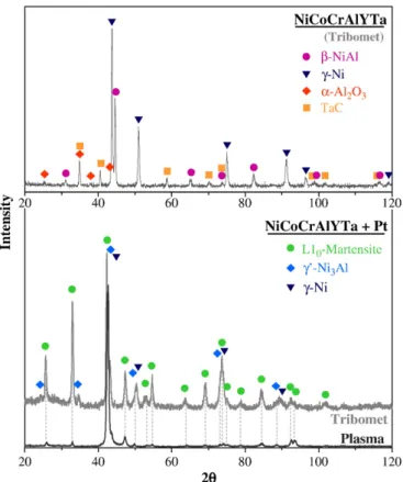
After the study of Pt diffusion through NiCoCrAlYTa by using EDS spectral maps, XRD analyses were performed on each bond coating deposited on AM3 superalloy after heat treatment, inθ–θ configura-tion (Fig. 5).
The XRD data obtained for the“Tribomet” NiCoCrAlYTa confirms the presence ofγ-Ni and β-NiAl phases and also tantalum carbides within the coating (onlyγ′-Ni3Al was not detected). Besides,α-Al2O3
peaks were identified. This could be the response of the oxides within the bond coating (Fig. 2b) but the peak intensity is much higher than expected when considering the volume fraction of oxides within the coating. Besides, oxides often contain yttrium and onlyα-Al2O3was
detected by XRD. Thus, these peaks should be related to bond coating oxidation during heat treatment.
With addition of Pt, L10martensite,γ′-Ni3Al, andγ-Ni phases were
detected in the outer part of the“Tribomet” Pt-modified NiCoCrAlYTa coating (Fig. 5). Martensite was also detected in the external part of the“Plasma” Pt-modified NiCoCrAlYTa coating (Fig. 5). However, it is difficult to know whether the “Plasma” coating was composed of γ-Ni orγ′-Ni3Al, or if it contained both phases. Tantalum carbides and
alumina were not detected in any Pt-modified NiCoCrAlYTa coatings. The absence of tantalum carbides within the external part of both Pt-modified NiCoCrAlYTa coatings confirms the results obtained after EDS spectral maps (Fig. 3).
To complete the results obtained by EDS spectral maps and XRD, TEM observations and electron diffraction analyses were performed on both Pt-modified NiCoCrAlYTa coatings. First, electron diffraction confirmed the presence of L10martensite within the external zone of
each bond coating, as seen on the selected area electron diffraction (SAED) pattern inFig. 6a. A martensite lath, observed in the“Plasma” Pt-modified NiCoCrAlYTa coating, is shown inFig. 6b. The martensite
Fig. 5. XRD of bond coatings after heat treatment, inθ–θ configuration.
region is indicated by the number‘1’ inFig. 7which corresponds to the cross-sections of the outer part of both Pt-modified NiCoCrAlYTa coatings. L10martensite appears in the BSE mode with the brightest
contrast.
Below martensite, the SAED pattern ofγ′-Ni3Al phase was obtained.
γ′-Ni3Al phase (Pm3
_
m space group) has a lattice parameter equal to 3.566 Å while the γ-Ni phase (Fm3_m space group) has a lattice parameter of 3.524 Å. Therefore, it is difficult to dissociate γ′-Ni3Al
alone from a mix ofγ′-Ni3Al/γ-Ni in cube/cube epitaxy. To solve this
problem, darkfield images were performed using γ′-Ni3Al reflexions
fromγ′-Ni3Al SAED patterns. Because it highlights theγ′-Ni3Al phase, it
indicates if grains are composed ofγ′-Ni3Al alone or of aγ′-Ni3Al/γ-Ni
mix. In this way,γ′-Ni3Al grains were identified in both bond coatings.
An example of a darkfield image constructed from the (01_1)γ′-Ni3Al
reflexion (Fig. 8a) is presented in Fig. 8b. The bright field image
corresponding to the darkfield image is presented inFig. 8c.γ′-Ni3Al
grains (which appear with a light grey contrast in the BSE mode) correspond to zone‘2’ ofFig. 7.
Grains with a darker contrast than those of martensite andγ′-Ni3Al
are also visible inFig. 7. They correspond to region number‘3’ which was located below theγ′-Ni3Al phase in both Pt-modified NiCoCrAlYTa
coatings. Besides, these grains were also visible up to the surface in the “Tribomet” Pt-modified NiCoCrAlYTa coating (Fig. 7a). A SEM observation of the“Tribomet” Pt-modified NiCoCrAlYTa surface after heat treatment under secondary vacuum confirmed that a third type of grain is found between the martensite and γ′-Ni3Al grains (dark
contrast inFig. 9a). They were composed offine precipitates (Fig. 9b). Further analyses were carried out in region number‘3’ ofFig. 7. The SAED patterns obtained correspond toγ′-Ni3Al phase. As previously,
darkfield images were obtained using γ′-Ni3Al reflexions to provide
Fig. 7. Cross-section of the outer part of the (a)“Tribomet” Pt-modified NiCoCrAlYTa bond coating, (b) “Plasma” Pt-modified NiCoCrAlYTa bond coating, after etching. SEM images in BSE mode. Number‘1’=L10martensite, number‘2’=γ′-Ni3Al, number‘3’=γ-Ni with a fine precipitation of γ′-Ni3Al. Arrows indicate oxides present at the original Pt/NiCoCrAlYTa
interface.
Fig. 8. From the“Plasma” NiCoCrAlYTa-Pt coating, observed in zone ‘2’ ofFig. 7: (a) [011] zone axis SAED pattern of aγ′-Ni3Al grain indicated by an arrow on (b), (b) TEM darkfield
more information. Thus,γ′-Ni3Al precipitates were highlighted and it
is concluded that the grains with a“dark contrast” were composed of a γ-Ni phase containing fine γ′-Ni3Al precipitates. An example of this is
given inFig. 9 where the (100) reflexion from the γ′-Ni3Al SAED
pattern (Fig. 9c) is used to make the darkfield image ofFig. 9d, with the“Plasma” Pt-modified NiCoCrAlYTa coating. The TEM bright field image ofFig. 9e also shows γ′-Ni3Al precipitates within the γ-Ni
matrix. Likewise, theγ′-Ni3Al precipitates are also revealed in the
SEM image withγ-Ni etching, as seen inFig. 9f which is the cross-section of the“Tribomet” Pt-modified NiCoCrAlYTa core.
In addition to the L10martensite,γ′-Ni3Al andγ-Ni phases, oxides
are found at the original Pt/NiCoCrAlYTa interface (Fig. 10). EDS analyses of the“Tribomet” Pt-modified NiCoCrAlYTa coating reveal the presence of Y and Al-rich oxides (indicated by the arrows on
Fig. 10a). Electron diffraction performed on the“Plasma” Pt-modified NiCoCrAlYTa coating (Fig. 10b) revealed that Y3Al5O12and α-Al2O3
were present (Fig. 10c and d respectively for areas 1 and 2 ofFig. 10b). Other oxides were found in the inner part of the “Tribomet” Pt-modified NiCoCrAlYTa coating, within the γ-Ni matrix (Fig. 11). They were rich in Al and/or Y. Their arrangement was sometimes
Fig. 9. (a) and (b)“Tribomet” NiCoCrAlYTa-Pt surface after heat treatment under secondary vacuum, SEM images in BSE mode. From the zone ‘3’ ofFig. 7, with the“Plasma” NiCoCrAlYTa-Pt coating: (c)γ′-Ni3Al SAED pattern whose (100) reflexion is used to create the TEM dark field image of γ′-Ni3Al precipitates withinγ-Ni matrix (d). (e) TEM bright
similar to the shape of the CrAlYTa particles. Such oxides were not found in the“Plasma” Pt-modified NiCoCrAlYTa coating.
Finally, very small precipitates were observed within the external zone of both Pt-modified NiCoCrAlYTa coatings (Pt-rich zone). A small proportion was identified by electron diffraction as being α-Cr precipitates. Although the other precipitates were very numerous, they did not diffract. Besides, EDS analyses performed on these unknown precipitates did not allow the composition of the precipitates to be clearly differentiated from that of the matrix. The only difference detected concerned the oxygen content. It seems that the oxygen concentration was higher in the precipitates than in the matrix.
The SEM, XRD, TEM and electron diffraction data obtained are summarized inFig. 12.
3.2.2. Pt effect on tantalum carbides
The“Tribomet” NiCoCrAlYTa coating contained numerous tantalum carbides. With the addition of Pt, the tantalum carbides disappeared from the external zone but remained within the coating in the region
close to the superalloy. No tantalum carbides were observed through the “Plasma” Pt-modified NiCoCrAlYTa coating.
The“Tribomet” Pt-modified NiCoCrAlYTa coating was also deposited on the MC-NG superalloy. The same microstructure as with AM3 superalloy was obtained. Nevertheless, few differences were noted. First, the coating depth containing tantalum carbides was greater with the MC-NG superalloy, as shown in SEM images ofFig. 13. EDS spectral maps were also obtained on the cross-section of the “Tribomet” Pt-modified NiCoCrAlYTa coating deposited on MC-NG. The Pt and Al concentrations are compared to those obtained for the same coating on the AM3 superalloy inFig. 13. It is clear that the quantity of Pt deposited on the surface of the NiCoCrAlYTa coating differed between the two superalloys. Calculation of the quantity of Pt using the integration of the concentration profiles revealed that 34% less Pt was deposited with the MC-NG superalloy than with the AM3 superalloy. The expected Pt thickness was 7μm, with an uncertainty of ±2 μm. This difference in Pt quantity corresponds to a difference in the Pt thickness of around 2.4μm. It is therefore within the “process tolerance”. Nevertheless, this could explain the variability in the coating microstructure.
XRD analysis was also performed on the“Tribomet” Pt-modified NiCoCrAlYTa bond coating deposited on MC-NG. The XRD pattern obtained was identical to that with the AM3 superalloy (Fig. 5). However, lattice parameters differed regarding the superalloy, as illustrated inTable 2.
Irrespective of the superalloy (AM3 or MC-NG), the lattice parameter ofγ-Ni within the NiCoCrAlYTa coating was found to be equal to 3.57 Å. With the addition of Pt, the lattice parameter increased and became greater than or equal to 3.60 Å (Table 2). By substituting for Ni inγ-Ni, γ′-Ni3Al,β-NiAl and L10martensite phases,
the Pt atom, which is larger than Ni, enlarges the lattice of these phases. However, it can be surprising to note that the lattice parameters depend on the superalloy on which is deposited the “Tribomet” Pt-modified NiCoCrAlYTa coating. Indeed, whatever the phase, the lattice parameters are greater with the AM3 superalloy, except the parameter‘a’ of martensite which was identical for both superalloys. This is consistent with the hypothesis that more Pt was deposited on the MC-NG superalloy.
A final comparison is done between all the “superalloy+bond coating” systems. Their cross-sections appear inFig. 14. Whereas the
[12-1] Y
3
Al
5
O
12
c
1
a
b
2
[241]
αα-Al
2
O
3
Fig. 10. (a) TEM image of“Tribomet” Pt-modified NiCoCrAlYTa coating. The arrows indicate Y and Al-rich oxides analyzed by EDS (in atomic percent ~19Al, 36Y, 36O). (b) TEM image of“Plasma” Pt-modified NiCoCrAlYTa coating, with oxides identified by electron diffraction: (c) Y3Al5O12SAED pattern obtained from point‘1’ and (d) α-Al2O3SAED pattern
obtained from point‘2’, zone axis [12-1] and [241] respectively.
Fig. 11. Oxides within theγ-Ni matrix, in the inner part of the “Tribomet” Pt-modified NiCoCrAlYTa coating. SEM image in BSE mode.
“Tribomet” NiCoCrAlYTa coating contained tantalum carbides through its entire depth (Fig. 14a), tantalum carbides were only located close to the superalloy when Pt was added to the “Tribomet” Pt-modified NiCoCrAlYTa (Fig. 14b and c). However, the depth affected by tantalum carbides was greater with the MC-NG superalloy than with the AM3 superalloy. Through the entire depth of the “Plasma” Pt-modified NiCoCrAlYTa coating, tantalum carbides were absent (Fig. 14d). Using
the Pt profile extracted from the EDS spectral map, the quantity of Pt deposited for the“Plasma” system is estimated to be 7% higher than that of the“Tribomet” Pt-modified NiCoCrAlYTa coating. Thus, the systems can be ranked according to their Pt concentration, from the lowest concentration to the highest:
“Tribomet”/AM3 bPt/“Tribomet”/MC-NG bPt/“Tribomet”/AM3 b Pt/“Plasma”/AM3.
Fig. 12. Cross-section of a (a)“Tribomet” Pt-modified NiCoCrAlYTa coating, (b) “Plasma” Pt-modified NiCoCrAlYTa coating.
Fig. 13. Composition profiles extracted from EDS spectral maps of NiCoCrAlYTa-Pt cross-sections on AM3 and MC-NG (SEM images in BSE mode). The dotted lines indicate the bond coating/superalloy interface.
They can also be ranked according to their tantalum carbides content, from the lowest to the highest:
Pt/“Plasma”/AM3 bPt/“Tribomet”/AM3 bPt/“Tribomet”/MC-NG b “Tribomet”/AM3.
It is interesting to note that the greater the Pt quantity added to the MCrAlY was, the lower the tantalum carbide content was.
4. Discussion 4.1. Pt effect on phases
After heat treatment under secondary vacuum, Pt-modified NiCoCrAlYTa coatings showed a sub-surface enriched in Al while their core was depleted of Al (Figs. 3 and 4). The presence of a Pt layer on the NiCoCrAlYTa surface led to an uphill diffusion of Al during heat treatment. Such an effect of Pt on Al diffusion in MCrAlY coatings has been observed only once by Raffaitin in an unpublished work[23]. This can be related to the study of Gleeson et al.[15]inγ-Ni/γ′-Ni3Al
coatings in which the uphill diffusion of Al was explained by a decrease in Al activity by Pt. For MCrAlYs, this means that the Al contained in the CrAlYTa particles (for“Tribomet” coating) or in the AMDRY splats (for “Plasma” coating) diffuses toward the Pt-rich surface andfinally forms L10martensite (Figs. 5, 6 and 12) and even
β-NiAl (analyzed by high-temperature XRD). This phenomenon is so extensive that no more β-NiAl phase was observed within the coating core, even close to the superalloy. Pt modified the entire NiCoCrAlYTa coating microstructure.
Martensite, which transforms intoβ-NiAl at high temperatures, dissolves little yttrium compared toγ′-Ni3Al orγ-Ni. This explains the
low/nil yttrium concentration (at least below the EDS detection limit) observed within the sub-surface of the “Plasma” Pt-modified NiCoCrAlYTa coating (Fig. 3). Concerning the yttrium concentration profile of the “Tribomet” Pt-modified NiCoCrAlYTa coating, the presence of martensite in the external part of the coating but also the fact that yttrium is partially trapped within tantalum carbides could explain the absence of this element within the sub-surface. The large yttrium concentration around the coating/superalloy interface
in the case of the“Plasma” Pt-modified NiCoCrAlYTa coating remains misunderstood at the moment.
The increase in tantalum concentration a few microns below the surface of both Pt-modified coatings is related to the presence of γ′-Ni3Al (below martensite) (Figs. 3 and 12). The coating core was
composed of a γ-Ni matrix with fine γ′-Ni3Al precipitates which
probably form during the slow cooling phase of the heat treatment. At a high temperature, the coating core would then be single-phased γ-Ni. γ-Ni grains (with fine γ′-Ni3Al precipitates) were also found up
to the surface of the “Tribomet” Pt-modified NiCoCrAlYTa coating (Fig. 7). This was not the case of the “Plasma” Pt-modified NiCoCrAlYTa coating for which a 10μm thick martensite layer was observed on top of a 5μm thick γ′-Ni3Al layer which was on top of the
internal γ-Ni/γ′-Ni3Al part. Nevertheless, martensite and γ′-Ni3Al
layers were not completely distinct as someγ′-Ni3Al grains were
found within the martensite layer of the “Plasma” Pt-modified NiCoCrAlYTa coating. These different microstructures could come from the manufacturing process used for NiCoCrAlYTa deposition. The “Tribomet” NiCoCrAlYTa coating consisted of CrAlYTa particles embed-ded in a (Ni,Co) matrix before Pt deposition. The microstructure was then heterogeneous in composition. The“Plasma” NiCoCrAlYTa coating was composed of NiCoCrAlYTa splats of constant composition. When interdiffusion occurs between the“Plasma” NiCoCrAlYTa coating of uniform composition and the Pt layer, the microstructure after heat treatment looks like superimposed “layers”. In the case where interdiffusion occurs between the “Tribomet” NiCoCrAlYTa coating of heterogeneous composition and the Pt layer,γ-Ni grains (with fine γ′-Ni3Al precipitates) were found up to the coating surface, among
martensite andγ′-Ni3Al grains. Therefore, it can be concluded that the
manufacturing process used for NiCoCrAlYTa deposition influences the Pt-modified NiCoCrAlYTa microstructure. This is due to the lack of chemical and microstructural homogeneity of the non-heat-treated “Tribomet” NiCoCrAlYTa coating. Indeed, the heat treatment that conventionally follows NiCoCrAlYTa deposition was postponed until after Pt deposition in the case of Pt-modified NiCoCrAlYTa coatings. If the heat treatment had been performed before Pt deposition, the microstructures of both“Tribomet” and “Plasma” NiCoCrAlYTa would have been closer and similar microstructures would have been expected.
As previously mentioned, martensite transforms intoβ-NiAl at high temperatures. The volume change associated with this transformation is around 2.0% ± 0.3%[25,26]. In Pt-modified aluminide coatings, this volume change can favour bond coating surface rumpling[27,28]. In the present study, martensite distribution differed according to the way in which the NiCoCrAlYTa was produced. This could lead to different lifetimes under thermal cycling conditions.
The fact that no β-NiAl grains were observed close to the superalloy indicates that Pt modified the coating through its entire depth. Because of their high Al concentration in the sub-surface
Table 2
Lattice parameters ofγ-Ni, γ′-Ni3Al and martensite L10phases present at the
sub-surface of the“Tribomet” Pt-modified NiCoCrAlYTa coating, determined using XRD.
γ-Ni γ′-Ni3Al Martensite L10
a (Å) a (Å) a (Å) c (Å) c/a
AM3 3.62 (6) 3.65 (4) 3.83 (5) 3.46 (7) 0.903
MC-NG 3.60 (4) 3.63 (5) 3.83 (0) 3.43 (0) 0.896
Fig. 14. Bond coating cross-sections, SEM images in BSE mode. (a)“Tribomet” NiCoCrAlYTa on AM3, (b) “Tribomet” Pt-modified NiCoCrAlYTa on MC-NG, (c) “Tribomet” Pt-modified NiCoCrAlYTa on AM3, (d)“Plasma” Pt-modified NiCoCrAlYTa on AM3.
designed to sustain high temperature oxidation while their Cr-rich inner part prevents hot corrosion ingress, such Pt-modified NiCoCrA-lYTa coatings can be considered to approach smart overlay coatings
[29].
Oxides were found at the original Pt/NiCoCrAlYTa interface in both Pt-modified bond coatings. Oxides were also observed within the core of the “Tribomet” Pt-modified NiCoCrAlYTa coating. Here again the manufacturing process used for NiCoCrAlYTa deposition explains this difference. Indeed, these oxides likely come from oxidized CrAlYTa particles used during the manufacturing of the alloy. The presence of oxides within the“Tribomet” Pt-modified NiCoCrAlYTa coating during the heat treatment prevents sufficient interdiffusion between the CrAlYTa particles and the (Ni,Co) matrix. The bond coating may contain some porosity after heat treatment that could be detrimental in service. On the contrary, metallic particles of known composition are melted and sprayed toward the superalloy in an environment with a low oxygen partial pressure in order to achieve“Plasma” NiCoCrAlYTa coating. This reducing atmosphere limits particle oxidation.
Veryfine precipitates were observed in the outer zone of both Pt-modified NiCoCrAlYTa coatings. Some are α-Cr precipitates showing that the external martensite or β-NiAl external layer was already saturated with Cr after the heat treatment. The other precipitates could not be properly identified as they do not diffract. It was only noted that they contain some oxygen. Therefore, these precipitates could be amorphous oxides but further analyses such as EELS are required to reach anyfirm conclusion.
From the various cross-sections of Pt-modified NiCoCrAlYTa coatings, it was noted that Pt does not have a smoothing effect on the bond coating surface whatever the process used for Pt deposition. This is in agreement with the observations of Lowrie and Boone on a Pt-modified CoCrAlY coating[7].
4.2. Pt effect on TaC
It was noted from Fig. 14 that the larger the quantity of Pt deposited on the NiCoCrAlYTa surface, the lower the TaC content. Carbon concentration within the system is unknown. However, carbon diffuses fast inγ-Ni at high temperatures[30]. Even if it is present in low quantity within the superalloy, carbon can easily diffuse toward the bond coating during the heat treatment (6 h at 1080 °C) to form carbides. Its concentration should therefore not be the limiting parameter for carbide formation. The presence of carbides within the material is dependent on the tantalum activity and carbon activity. Tantalum is aγ′-gene element, as is Al. Besides, it is now well known that Pt decreases Al activity. Hence, an effect similar to that observed for Al activity can be expected with Ta activity due to Pt addition. Pt could decrease Ta activity and then decompose the carbides. Nevertheless, more work needs to be done to check this last point.
4.3. Expected Pt effect on oxidation/corrosion resistance
The addition of Pt resulted in a great increase in the Al concentration within the external part of the coatings. This should favour the selective oxidation of Al and consequently improve the oxidation resistance of such coatings. In addition to this, the core of the coating remains rich in chromium, which is beneficial for the resistance to hot corrosion. Therefore, these new coatings appear very promising for high-temperature applications in oxidizing and corrosive environments. Nevertheless, the dissolution of the tantalum carbides, which was assumed to be due to Pt addition, and the presence of martensite could be an issue. Without any or with very few tantalum carbides, titanium could diffuse easily from the superalloy toward the surface of the coating, oxidize and disrupt the protective oxide layer[31]. Because martensite transforms toβ-NiAl at high temperatures, stresses could develop and lead to the surface deformation.
5. Conclusions
This works deals with the effect of Pt on the microstructure of two NiCoCrAlYTa coatings, manufactured using different processes. First, it was shown that Al diffuses extensively from the bulk NiCoCrAlYTa toward the external Pt-rich zone. The sub-surface becomes enriched in Al and L10 martensite (even β-NiAl) forms. Such aluminium
diffusion is the consequence of the decrease in Al activity in the presence of Pt, as already demonstrated by other authors in other systems. Al diffusion is so extensive that the β-NiAl phase was no longer observed within the coating core. The external zone of the Pt-modified NiCoCrAlYTa coating was therefore Al-rich while the core of the coating was Cr-rich. This layering should provide a good oxidation and hot corrosion resistance and protect the superalloy.
Martensite,γ′-Ni3Al andγ-Ni phases occurred in both Pt-modified
NiCoCrAlYTa coatings. However, their distribution differed regarding the NiCoCrAlYTa manufacturing process. When vacuum plasma spraying was used, the microstructure after heat treatment was more uniform compared to that obtained when the NiCoCrAlYTa coating was made by the“Tribomet” process. If the heat treatment was performed before Pt deposition, the microstructures of both Pt-modified NiCoCrAlYTa coatings (“Tribomet” and “Plasma”) would be closer.
Pt, which clearly affects Al activity, also seems to decrease Ta activity leading to TaC dissolution. Further investigation should confirm this last point.
Acknowledgments
Turbomeca (Safran Group) is gratefully acknowledged for providing the samples and for thefinancial support of this study. Authors express their thanks to Praxair ST which manufactured the“Tribomet” bond coatings modified and non-modified by Pt, Professor J. R. Nicholls for the Pt sputtering, LERMPS laboratory for the VPS NiCoCrAlYTa coatings, Turbomeca and CNRS for the doctoral grant of A. Vande Put.
References
[1] L. Peichl, D.F. Bettridge, in: D. Coutsouradis, et al., (Eds.), Materials for Advanced Power Engineering, Part I, Proc. Int. Conf. 1994, Liege, Kluwer Acad. Publ., Dordrecht, 1994, p. 717.
[2] J.R. Nicholls, JOM 52 (2000) 28.
[3] R. Streiff, D.H. Boone, J. Mater. Eng. 10 (1988) 15.
[4] A.L. Purvis, B.M. Warnes, Surf. Coat. Technol. 146–147 (2001) 1. [5] N. Vialas, D. Monceau, Surf. Coat. Technol. 201 (2006) 3846. [6] E.J. Felten, Oxid. Met. 10 (1976) 23.
[7] R. Lowrie, D.H. Boone, Thin Solid Films 45 (3) (1977) 491. [8] T.A. Taylor, D.F. Bettridge, Surf. Coat. Technol. 86–87 (1996) 9.
[9] W.J. Quadakkers, V. Shemet, D. Sebold, R. Anton, E. Wessel, L. Singheiser, Surf. Coat. Technol. 199 (2005) 77.
[10] N.M. Yanar, F.S. Pettit, G.H. Meier, Metall. Mater. Trans. A 37A (2007) 1563. [11] A. Feuerstein, J. Knapp, T. Taylor, A. Ashary, A. Bolcavage, N. Hitchman, J. Therm.
Spray Technol. 17 (2008) 199.
[12] D. Oquab, D. Monceau, Y. Thébault, C. Estournes, Mater. Sci. Forum 595–598 (2008) 143. [13] J. Benoist, K.F. Badawi, A. Malié, C. Ramade, Surf. Coat. Technol. 182 (2004) 14. [14] J. Benoist, K.F. Badawi, A. Malié, C. Ramade, Surf. Coat. Technol. 194 (2005) 48. [15] B. Gleeson, W. Wang, S. Hayashi, D. Sordelet, Mat. Sci. Forum 461–464 (2004) 213. [16] E. Copland, J. Phase Equilib. Diffus. 28 (2007) 38.
[17] E. Copland, Technical Report NASA/CR-2005-213330, NASA, 2005.
[18] J. Foster, Electrolytic or electroless codeposition of particles and metal, patent GB2254338A (1992).
[19] D.S. Rickerby, Mater. Manuf. Process. 7 (1992) 495.
[20] A. Raffaitin, F. Crabos, E. Andrieu, D. Monceau, Surf. Coat. Technol. 201 (2006) 3829. [21] A. Boudot, PhD thesis, Institut National Polytechnique de Toulouse (1999). [22] S. Dryepondt, PhD thesis, Institut National Polytechnique de Toulouse (2004). [23] A. Raffaitin, PhD thesis, Institut National Polytechnique de Toulouse (2007). [24] N. Vialas, PhD thesis, Institut National Polytechnique de Toulouse (2004). [25] M.W. Chen, M.L. Glynn, R.T. Ott, T.C. Hufnagel, K.J. Hemker, Acta Mater. 51 (2003) 4279. [26] M.W. Chen, R.T. Ott, T.C. Hufnagel, P.K. Wright, K.J. Hemker, Surf. Coat. Technol.
163–164 (2003) 25.
[27] Y. Zhang, J.A. Haynes, B.A. Pint, I.G. Wright, W.Y. Lee, Surf. Coat. Technol. 163 (2003) 19.
[28] D.S. Balint, J.W. Hutchinson, J. Mech. Phys. Solids 53 (2005) 949.
[29] J.R. Nicholls, N.J. Simms, W. Chan, H.E. Evans, Surf. Coat. Technol. 149 (2002) 236. [30] S.K. Bose, H.J. Grabke, Z. Metallkunde 69 (1978) 8.


![Fig. 8. From the “Plasma” NiCoCrAlYTa-Pt coating, observed in zone ‘2’ of Fig. 7: (a) [011] zone axis SAED pattern of a γ′-Ni 3 Al grain indicated by an arrow on (b), (b) TEM dark field image highlighted with (01_](https://thumb-eu.123doks.com/thumbv2/123doknet/3694088.109678/7.892.195.688.76.383/plasma-nicocralyta-coating-observed-pattern-indicated-field-highlighted.webp)


