HAL Id: tel-02899601
https://pastel.archives-ouvertes.fr/tel-02899601
Submitted on 15 Jul 2020
HAL is a multi-disciplinary open access archive for the deposit and dissemination of sci-entific research documents, whether they are pub-lished or not. The documents may come from teaching and research institutions in France or abroad, or from public or private research centers.
L’archive ouverte pluridisciplinaire HAL, est destinée au dépôt et à la diffusion de documents scientifiques de niveau recherche, publiés ou non, émanant des établissements d’enseignement et de recherche français ou étrangers, des laboratoires publics ou privés.
Direct synthesis of long-chain hydrocarbons by
plasma-catalysis from syngas and CH4-CO2 mixtures
Di Li
To cite this version:
Di Li. Direct synthesis of long-chain hydrocarbons by plasma-catalysis from syngas and CH4-CO2 mixtures. Chemical and Process Engineering. Université Paris sciences et lettres, 2019. English. �NNT : 2019PSLEM059�. �tel-02899601�
Soutenue par
Di LI
Le 28/11/2019
Spécialité
Energétique et génie des
procédés
Ecole doctorale ISMME n° 621 :
Ingénierie des Systèmes,
Matériaux, Mécanique et
Energétique
Direct synthesis of long-chain hydrocarbons by
plasma-catalysis from syngas and CH
4-CO
2mixtures
Synthèse directe d'hydrocarbures supérieurs par
plasma-catalyse à partir de gaz de synthèse et de
mélanges CH
4-CO
2Préparée à MINES ParisTech
Composition du jury:
Elena Galvez Parruca
Maitre de conf. HDR UPMC Rapporteur
Xin Tu
Reader, University of Liverpool Rapporteur
Catherine Batiot Dupeyrat
Prof. Université de Poitiers Examinateur
Patrick Da Costa
Prof. Sorbonne Université Président de jury
Vandad-Julien Rohani
Maitre-assistant, MINES ParisTech Examinateur
Laurent Fucheri
1
Contents
NOMENCLATURE ... 5 ABBREVIATIONS ... 5 SYMBOLS ... 7 RESUME EN FRANÇAIS ... 8 CHAPTER I. INTRODUCTION ... 15 1.1.BACKGROUND ... 151.2.A BRIEF INTRODUCTION TO PLASMA ... 19
1.3.A REVIEW ON FTS ... 21
1.3.1 Main reactions and mechanism of FTS ... 24
1.3.2 Catalysts for FTS ... 30
1.4.A REVIEW ON REFORMING CO2 WITH CH4 ... 35
1.4.1 Reactions and thermodynamics... 36
1.4.2 Catalysts for reforming ... 39
1.4.3 New approach: directly synthesizing value-added liquid products from CO2 and CH4 ... 42
1.5.WHY PLASMA-ASSISTED REFORMING AND FTS MAKES A DIFFERENCE ... 45
1.5.1 Plasma assisted FTS ... 46
1.5.2 Plasma assisted converting CO2 with CH4... 47
1.6.OUTLINE OF THIS THESIS ... 50
CHAPTER II. EXPERIMENTAL, METHOD CHARACTERIZATIONS AND SYSTEM DIAGNOSTICS ... 53
RESUME DU CHAPITRE ... 53
ABSTRACT ... 54
2.1.DESCRIPTION OF EXPERIMENTAL BENCH ... 55
2.1.1 DBD reactor ... 56
2
2.1.3 Power measurement and diagnostics ... 57
2.1.4 Measurement and products analysis ... 59
2.2.PREPARATION AND CHARACTERIZATION OF CATALYSTS ... 61
2.2.1 Preparation of catalysts ... 61
2.2.2 Characterization of catalysts ... 63
2.3.CHARACTERIZATION RESULTS OF CATALYSTS ... 65
2.3.1 Textural properties of Co/SiO2 aerogel catalysts ... 65
2.3.2 Structural properties of cobalt species ... 67
2.3.3 Electron microscope ... 71
2.4.SYSTEM DIAGNOSTICS ... 75
SUMMARY ... 79
CHAPTER III. PLASMA-CATALYTIC CONVERSION OF CO AND H2 ... 81
RESUME DU CHAPITRE ... 81
ABSTRACT ... 82
3.1.INTRODUCTION... 83
3.2.PLASMA TESTS WITHOUT CATALYST ... 84
3.2.1 H2/CO ratio ... 86
3.2.2 Total flow rate ... 88
3.2.3 Frequency... 90
3.3. PLASMA TESTS WITH CATALYSTS ... 92
CONCLUSION ... 99
CHAPTER IV. PLASMA-CATALYTIC CONVERSION OF CO2 AND CH4 ... 101
RESUME DU CHAPITRE ... 101
ABSTRACT ... 102
4.1.INTRODUCTION... 102
4.2.EXPERIMENTAL ... 105
3
4.2.2 Experimental analysis ... 107
4.3.RESULTS AND DISCUSSION ... 109
4.3.1 Characterization of catalysts ... 109
4.3.2 Thermodynamic equilibrium calculation ... 116
4.3.3 Plasma experiments without catalysts ... 118
4.3.4 Plasma experiments with catalysts ... 124
4.4.SUMMARY ... 131
CHAPTER V. DIRECT SYNTHESIS OF LIQUID CHEMICALS AND FUELS FOR CO2 AND CH4 ... 133
RESUME DU CHAPITRE ... 133
ABSTRACT ... 134
5.1.INTRODUCTION... 135
5.2.EXPERIMENTAL AND MATERIALS ... 137
5.2.1 HZSM-5 and Co or Fe doped zeolite catalysts ... 137
5.2.2 Experimental configuration ... 138
5.3.CHARACTERIZATION OF ZEOLITE CATALYSTS ... 141
5.3.1 N2 adsorption/desorption ... 141
5.3.2 X-ray diffraction ... 142
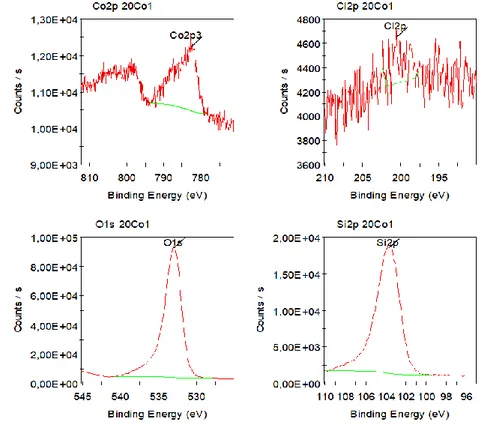
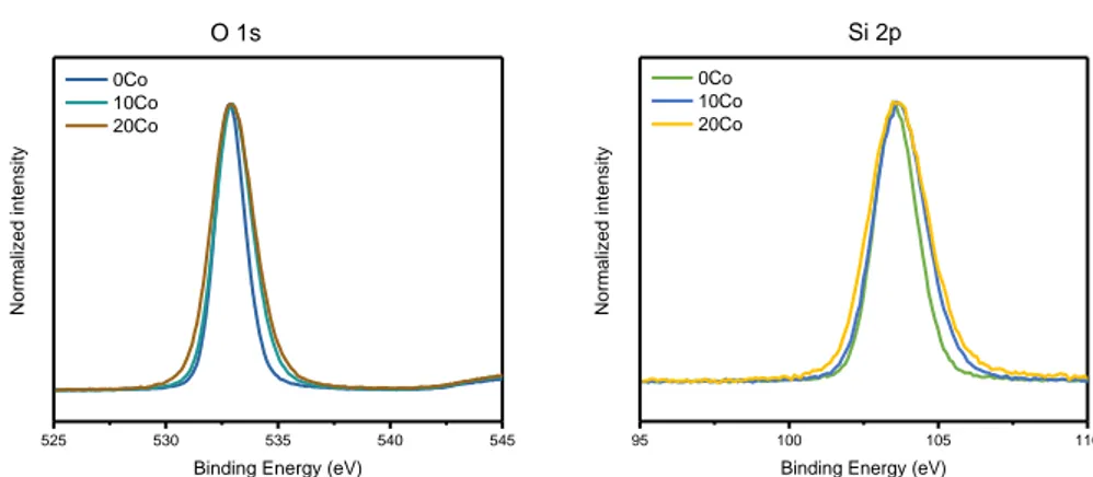
5.3.3 X-ray photoelectron spectroscopy ... 144
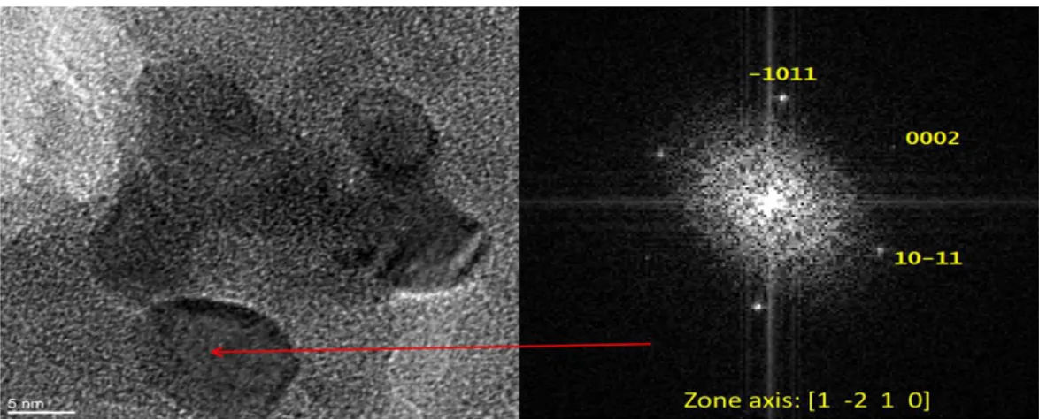
5.3.4 SEM and TEM ... 147
5.3.4 TG analysis ... 150
5.4.PLASMA EXPERIMENTS ... 152
5.4.1 Effects of packing zeolite ... 152
5.4.2 Composite catalysts and packing method ... 155
5.4.3 Effects of CO2/CH4 ratio on the performance of composite catalysts ... 164
5.5.SUMMARY ... 172
4
CONCLUSIONS ET PERSPECTIVES D’AVENIR ... 174
6.1.COMPARISON WITH LITERATURE ... 176
6.1.1 Plasma-catalytic conversion of CO with H2 ... 177
6.1.2 Plasma-catalytic conversion of CO2 with CH4 ... 178
6.2.CONCLUSIONS ... 181
6.2.1 Plasma-catalytic FTS ... 181
6.2.2 Plasma-catalytic conversion of CO2 with CH4 ... 183
6.3.FUTURE PERSPECTIVES AND RECOMMENDATION ... 186
REFERENCES ... 188
5
Nomenclature
Abbreviations
FTS, Fischer-Tropsch Synthesis; BTL, Biomass To Liquids; GTL, Gas To Liquids;WGS, Water Gas Shift Reaction;
RWGS, Reverse Water Gas Shift Reaction; NTP, Non-thermal Plasma;
DBD, Dielectric Barrier Discharge; DMR, Dry Methane Reforming;
SSITKA, Steady State Isotopic Transient Kinetic Analysis; HV, High Voltage;
BET, Brunauer-Emmett-Teller; BIH, Barrett-Joyner-Halenda;
IUPAC, International Union of Pure and Applied Chemistry; XRD, X-Ray Diffraction;
NIST, National Institute of Standards and Technology; PDF, Powder Diffraction File;
FWHM, Full Width at Half Maximum; XPS, X-Ray Photoelectron Spectroscopy; SEM, Scanning Electron Microscope; TEM, Transmission Electron Microscope;
STEM, Scanning Transmission Electron Microscopy;
HRTEM, High-resolution Transmission Electron Microscopy; EDS, Energy-dispersive X-Ray Spectroscopy;
6 GIF, Gatan Imaging Filter;
HAADF, High-angle Annular Dark-field Imaging; FCC, Face-centered Cubic;
CCD, Charge-coupled Device;
DRIFTS, Diffuse Reflectance Infrared Fourier Transform Spectroscopy; NMR, Nuclear Magnetic Resonance Spectroscopy;
TGA, Thermogravimetric Analysis;
FT-IR, Fourier-transform Infrared Spectroscopy; GC, Gas Chromatography;
MS, Mass Spectrometry;
GC-MS, Gas Chromatography-Mass Spectrometry; Rt-Molsieve, fused silica PLOT column;
Rt-Q-Bond, fused silica PLOT column; TCD, Thermal Conductivity Detector; P75W20, polyethoxydisiloxane;
APTES, (3-Aminopropyl) triethoxysilane; HMDZ, hexamethyldisilazane;
BE, Binding Energy;
SIE, Specific Input Energy; EE, Energy Efficiency;
Cx, hydrocarbon molecular including x carbon atoms; MTHC, Methanol to Hydrocarbons;
HHV, High Heating Value; LHV, Low Heating Value; 𝐶𝐵, Carbon Balance; 𝐸𝐶, Energy Cost;
7
Symbols
i, current; Q and q, charge; U and V, voltage; Vpp, peak-to-peak voltage; R, resistance; C, capacitance; L, inductance; 𝐸𝑎, activation energy; P, power; W, energy;x𝑛, conversion rate of reactant n;
xtotal, total conversion rate of reactants; 𝑆𝑛, selectivity to product n;
𝑆CH4/CO, selectivity of CH4 to CO; 𝐸𝑛, energy efficiency of reactant n; 𝑌𝑛, yield of product n;
R, ratio of unsaturated hydrocarbons/saturated hydrocarbons; Err, experimental uncertainties;
8
Résumé en Français
Le réchauffement planétaire lié à l'accumulation continue de gaz à effet de serre dans l'atmosphère au cours des derniers siècles, constitue l'un des problèmes les plus critiques des sociétés modernes. La surexploitation de combustibles fossiles tels que le charbon et le pétrole a conduit à l’émissions d’énormes quantités de CO2 dans l’atmosphère et a intensifié de manière considérable l'effet de serre atmosphérique naturel, provoquant un important réchauffement planétaire et un dérèglement climatique dont les conséquences pourraient s’avérer dramatiques pour l’avenir même de l’humanité.
D’un autre côté, la demande mondiale en combustibles fossiles, en particulier de pétrole, ne cesse d’augmenter chaque année. Dans ce contexte, la production d’hydrocarbures synthétiques liquides (et d’oxydes d'hydrocarbures) à partir de matière renouvelable (biomasse, déchets) ; de CO2 ; de méthane (gaz naturel ou biogaz) via les procédés BTL (Biomass To Liquids) ou GTL (Gas To Liquids), pouvant éventuellement être associés à des installations de captage du CO2, suscitent un intérêt croissant dans la plupart des pays industrialisés.
En parallèle, de nombreuses recherches sont en cours pour la capture du CO2 sur des sites industriels centralisés (centrales thermiques, pétrochimie, cimenteries, sidérurgie,…). Dans ce contexte, la rétro-conversion du dioxyde de carbone et la synthèse Fischer-Tropsch (FTS) pourraient, dans l’avenir, jouer un rôle majeur pour la production de carburants liquides « faiblement carbonés ».
Le méthane, est un gaz à effet de serre qui existe dans la nature (gaz naturel, biogaz). De grandes quantités de CH4 (notamment dans les champs de gaz associé au pétrole) restent inexploitées et sont gaspillées, souvent directement brûlées (torchées) en raison des difficultés de stockage et des coûts de transport.
Au cours du siècle dernier, de nombreux efforts ont été consacrés à l’étude de la conversion de Méthane en produits liquides à plus forte valeur ajoutée et ainsi de
9 surmonter les inconvénients liés au stockage et au transport.
Dans ce contexte, en « consommant » de deux gaz à effet de serre, le reformage catalytique à haute température, du CH4 au CO2 qui permet de produire du gaz de synthèse (mélange CO/H2) connait un regain d’intérêt par rapport à d’autres méthodes de reformage telles que le reformage à la vapeur (steam reforming). De plus, la synthèse Fischer Tropsch (FTS), permet de transformer le gaz de synthèse en hydrocarbures liquides, et autres composés oxygénés organiques à forte valeur ajoutée. La combinaison de ces deux techniques pourrait constituer une solution réaliste au recyclage du CO2 anthropique et à la diversité énergétique pendant la période de transition actuelle.
La molécule de CO2 est bien connue sur le plan thermodynamique et son activation nécessite l’apport d’une importante quantité d'énergie. Ainsi, le reformage du CO2 et du CH4 (couramment appelé reformage à sec) nécessite un important apport d’énergie ; des températures élevées (supérieure à 600 °C), et l’ajout de catalyseurs spécifiques.
Le plasma, en tant que milieu fluide chimiquement actif, est maintenant largement utilisé dans de nombreux domaines industriels tels que : revêtements, gravure, traitement de surfaces, synthèse de matériaux, destruction de déchets, traitement des gaz, synthèse chimique, soudage, découpage… Il offre un moyen unique et attrayant pour activer et déclencher certaines réactions chimiques et apporter de l’énergie à un processus endothermique. Les plasmas peuvent facilement être générés par apport d’énergie électrique (en appliquant une tension par exemple) ce qui apparait particulièrement intéressant pour le futur dans la perspective d’un large déploiement des ENR (solaire, éolien, biomasse) pour la production d'énergie électrique faiblement carbonée. En conséquence, l’utilisation de plasma offre de nouvelles perspectives pour (i) de remplacement des procédés thermiques basés sur la combustion et (ii) le stockage d’ énergie électrique renouvelable, qui par nature est intermittente, sous forme de produits chimiques (Power To X).
10 Ainsi, le procédé FTS plasmocatalytique et la conversion directe du CO2 et du CH4 en produits liquides de forte valeur ajoutée apparaissent comme des voies prometteuses pour l’utilisation du CO2 permettant de surmonter certains inconvénients des voies thermochimiques traditionnelles telles que la pression et la température élevées. L’objectif de cette thèse concerne l’étude de la conversion directe du CO2 et du CH4 en produits liquides de forte valeur ajoutée par un procédé plasma-catalyse.
Après un premier chapitre introductif, le Chapitre II est consacré à la description et au diagnostic électrique du banc d’expérimentation. Tout d'abord, nous avons mis en place un réacteur plasma à barrière diélectrique (DBD) tubulaire avec ses appareils d'analyse physiques et chimiques. Le réacteur DBD comprend deux électrodes en configuration coaxiale, un tube en céramique diélectrique et deux bouchons ajustables aux extrémités. Un catalyseur solide se présentant sous la forme de granules catalyseur/support vient remplir l’espace inter-électrode entre l’électrode interne et le tube diélectrique. La puissance électrique est fournie par un générateur à courant variable. La puissance injectée dans le plasma DBD est calculée via la méthode de Lissajous en plaçant une capacité en série avec le réacteur. Les produits gazeux sont analysés en ligne par Chromatographie en phase Gazeuse (GC). Les liquides sont séparés des gaz par un piège à eau glacée, puis ils sont analysés hors ligne via un Chromatographe en phase Gazeuse couplé à un spectromètre de masse (GC-MS). Il est important de noter que des sondes de température et de pression, situées à l'entrée et à la sortie du réacteur, enregistrent température et pression avant et pendant décharge, afin de calibrer les résultats de conversion et sélectivité. Pour cerner les caractéristiques électriques du réacteur, des décharges ont d'abord été générées sous une atmosphère gazeuse inerte pour la caractérisation. L'aérogel de silice utilisé comme support de catalyseur avec la zone spécifique élevée a été préparé via un procédé de séchage à l'air ambiant après traitement de surface par HMDZ afin d’obtenir des surfaces spécifiques importantes et une hydrophobicité. Le catalyseur
11 Co a été synthétisé par deux procédés différents pour étude comparative : un procédé d'imprégnation et un procédé sol-gel via précurseur. Les différentes qualités de catalyseur Co obtenues ont été caractérisées par diverses méthodes.
Le chapitre III est consacré à l'étude expérimentale de la synthèse d'hydrocarbures à partir de gaz de synthèse par plasma non-thermique associé à de la catalyse hétérogène. Remplacer une synthèse thermo-catalytique à haute pression de type Fischer-Tropsch par une synthèse plasmocatalytique à pression atmosphérique pourrait conduire à un gain d’énergie pour la production d’hydrocarbures et d’oxydes organiques synthétiques. La première partie de ce chapitre est consacrée à la conduite d’essais de synthèse à partir de gaz de synthèse par plasma seul (sans catalyseur), à pression atmosphérique. Ces essais ont été réalisés à différents débits de gaz de synthèse, de rapports H2/CO et de fréquence d’excitation du plasma, afin d’évaluer l’efficacité du plasma seul. Puis, la deuxième partie du chapitre présente les essais avec l’ajout de cobalt comme catalyseur sur support d’aérogel de silice, dans une configuration de réacteur rempli. Les résultats indiquent que des quantités considérables d'hydrocarbures C1-C5 ont été synthétisées dans des conditions ambiantes avec des énergies d'entrée spécifiques relativement basses (inférieures à 18 kJ/l). De plus, le catalyseur Co sur support d’aérogel de silice semble favoriser non seulement la synthèse d'hydrocarbures C2-C5, mais aussi la formation d'oxydes organiques liquides. Les catalyseurs cobalt obtenus par procédé d'imprégnation avec un précurseur de nitrate (présenté en chapitre 2) ont montré une excellente performance catalytique dans cette configuration de réacteur. Sur la base des connaissances existantes sur le sujet, des voies de réaction possibles sont alors proposées. Les résultats obtenus dans ce chapitre démontrent au final qu’une nouvelle approche de synthèse organique à partir de syngaz est possible, en alternative à la synthèse Fischer-Tropsch traditionnelle.
Le chapitre IV aborde l’étude de la conversion plasmocatalytique directe à pression et température ambiantes de CO2 et CH4 en produits liquides (hydrocarbures,
12 alcools, cétones, etc.) et gaz de synthèse. Pour cela le même réacteur rempli a été utilisé, testé avec différents catalyseurs sur support d’aérogel de silice (Co et Fe) et pour différents rapports CO2/CH4. Là encore la même démarche que le chapitre précédent a été suivie, à savoir une série d’essais en plasma seul, puis une avec introduction du catalyseur sur son support d’aérogel. La performance des catalyseurs en couplage plasmocatalytique a ainsi été évaluée. Selon les conditions opératoires, la sélectivité globale en CO et H2 peut atteindre respectivement 75% et 50%, les taux de conversion du CO2 et du CH4 environ 30% et 43%. Il est constaté que le rapport CO2/CH4 affectait de manière significative les taux de conversion et la distribution des produits finis. Peu de liquides sont produits sans catalyseur, le catalyseur favorise clairement la synthèse de produits liquides. De plus, le support d’aérogel augmente les taux de conversion des réactifs et améliore légèrement la sélectivité vis-à-vis des produits liquides. La sélectivité en produits liquides peut atteindre jusqu’à 40% avec catalyseur sur support d’aérogel. Les principaux produits liquides étant le méthanol et l'acide acétique. En faisant varier les taux de CH4 et de CO2 en couplage plasmocatalytique nous produisons un petit nombre d'hydrocarbures à longue chaîne (hexane, heptane) mais aussi d'alcools (hexanol). La synergie positive de la catalyse et du plasma pour la conversion du CH4 et CO2 semble ainsi démontrée. Cela représente de façon évidente un potentiel pour la synthèse directe de produits chimiques liquides à valeur industrielle et de carburants à partir de CO2 et de CH4.
Le chapitre V est dédié à l’étude de la synthèse directe de produits liquides à partir de CO2 et CH4 à l’aide du réacteur plasmocatalytique du chapitre précédent dans lequel il a été introduit non pas un catalyseur mais deux en même temps. Des combinaisons simples ou mixtes sont ainsi effectuées et testées parmi les matériaux suivants : Co, Fe, SiO2 et HZSM-5. Les catalyseurs sont disposés dans le réacteur sous forme de granules mixtes (préparés par dopage/imprégnation) ou simples, mélangés ou séparés (configuration double lits). Les résultats semblent montrer que l’association sous forme de granules mixtes Co/HZSM-5 est particulièrement
13 favorable à la conversion directe de CO2 et CH4 en produits liquides à longue chaîne. L’association sous forme de granules mixtes Fe/HZSM-5 permet de son côté d’obtenir lorsque la proportion de CO2 est élevée une sélectivité importante vis-à-vis du méthanol. L’association en configuration double lits de granules Fe / aérogel de silice et de granules de HZSM-5 permet quant à elle, lorsque la proportion de CH4 est élevée, d’atteindre une importante sélectivité vis-à-vis de l’acétique acétique. La synergie positive entre la combinaison de deux catalyseurs et du plasma pour la production de produits liquides à partir de CO2 et CH4 est ainsi démontrée.
Pour résumer, cette thèse a initié une première étude complète sur : (i) d’une part, la synthèse Fischer-Tropsch et (ii) d’autre part, la conversion directe du CO2/CH4, par la voie plasmocatalytique en conditions de pression et température ambiantes. Tandis que la synthèse Fischer-Tropsch plasmocatalytique ne permet pour l’heure de produire de chaines carbonées supérieures à C4, la conversion plasmocatalytique du CO2/CH4 montre elle un remarquable potentiel pour la production de composés liquides : alcools, acides carboxyliques et hydrocarbures à longue chaine C5+. Dans ce dernier cas, le passage à l’emploi simultané de deux catalyseurs à la place d’un seul permet de manipuler la distribution des produits liquides tout en améliorant la sélectivité vis-à-vis des hydrocarbures à longue chaine et le taux de conversion global du CO2/CH4. Les travaux de cette thèse démontrent ainsi la faisabilité d’une conversion plasmocatalytique efficace d’un mélange CO2/CH4 en carburants de synthèse ou molécules nobles. Sur la base de nos travaux et en perspective des travaux futurs, quelques recommandations peuvent être finalement émises dont la nécessité de :
1. Optimiser la source de plasma afin de mieux contrôler l’énergie spécifique injectée et l’élévation de la température électronique. Cela passe en grande partie par l’évolution de l’alimentation électrique et davantage d’accord avec la décharge.
2. Améliorer les catalyseurs : lien plus fort entre le catalyseur et son support, meilleurs aérogels et meilleurs couches catalytiques en termes de porosité et
14 structuration, nouvelles combinaisons catalytiques, étendre la gamme métallique des catalyseurs, l’emploi simultanée de plusieurs catalyseurs, introduction de promoteurs tels que des métaux alcalins…
3. Compléter l’étude de l’influence de la stœchiométrie du gaz réactif sur la conversion et les produits.
4. Etudier l’effet d’une dilution du gaz réactif dans un gaz plasmagène inerte. 5. Enfin, tenter de modéliser la chimie en phase plasma puis la conversion plasmocatalytique dans son ensemble en cherchant à savoir s’il y a une interaction directe entre le plasma et le catalyseur.
15
Chapter I. Introduction
1.1. Background
In recent centuries, global warming due to the continuous accumulation of
greenhouse gases in the atmosphere has been one of the most critical issues. The
overuse of fossil fuels such as coal and oil, have contributed to the excessive emission of CO2 and mightily intensified the atmospheric greenhouse effect and climate change, causing global warming according to the statistical data from International Energy Agency (IEA) (Figure 1-1) [1]. However, the demands of fossil fuels, especially oil production, continue increasing with each passing year, as shown in Figure 1-2 [2]. Under this context, the synthetic hydrocarbons and hydrocarbon oxides produced from biomass, CO2, natural gas, biogases and wastes through BTL (Biomass To Liquids) or GTL (Gas To Liquids) process integrated with CO2 capture have drawn significant interests for researchers in recent years.
Figure 1-1. CO2 emission by the combustion of fossil fuel from 2000 to 2014 [1].
20 000 40 000 60 000 80 000 100 000 120 000 140 000 200020012002200320042005200620072008200920102011201220132014 millio n t on n es of C O2 International aviation bunkers International marine bunkers Non-OECD Total OECD Total Annex B Kyoto Parties Non-Annex I Parties Annex I EIT Asia Oceania Europe North America Annex II Parties
16
Figure 1-2. World total primary energy supply (TPES) from 1971 to 2014 by fuel (Mtoe) [2].
Carbon capture and storage (CCS) is the process of capturing waste CO2 usually from the use of fossil fuels in electricity generation and industrial processes, such as cement factories, oil refinery plants or biomass power plants, transporting it to a storage site, and then depositing it usually under an underground geological formation. Until now, abundant efforts have been made in the technique of CCS and other the related fields and techniques of BTL or GTL during recent decades. Since time has mellowed them, the installation of CO2 capture devices has been more and more frequent in the industrial field especially in thermal power plants and natural gas processing as the statistics data shown in Figure 1-3 [3]. However, the subsequent storage of CO2 after capture has significant drawbacks regarding the high investment, transportation, and uncertainty of long-term storage [4]. Thus, Carbon Dioxide Reforming and Fischer–Tropsch synthesis (FTS) can play a crucial role to sustain liquid fuel consumption and achieve a low carbon economy while avoiding the drawbacks of storage in industries.
17
Figure 1-3. Large-scale CO2 capture projects from 1996 [3].
Methane, as one of the greenhouse gases, is widely existed in nature (such as shale gas, biogas, and oil fields). A large amount of CH4 is directly combusted due to difficulties of storage in many industries such petroleum industry, oil refinery, and coal industry. Great efforts have been devoted to the study of Methane to Liquid during the past century to produce value-added liquid products and overcome the drawbacks of storage and transportation. Benefitting from the consumption of two greenhouse gases, CO2 reforming with CH4, which is a method to produce syngas products with a catalyst at a high temperature, has become more attractive than other reforming methods such as steam reforming. Moreover, FTS, as a relatively advanced and promising technique, is a process to transform syngas into liquid paraffin, olefins, and another value-added organic oxygenates. The combination of these two techniques could be a feasible solution to anthropogenic CO2 recycling and energy diversity during the transitional period from the current fossil fuel-based stage to the final sustainable age.
Indeed, the FTS process is typically achieved in two steps by integrating with petroleum industry processes or coal industry processes, where CH4 and CO2 can be easily available to satisfy the demand of feedstocks in many plants. The direct utilization and reformation of CH4 byproducts with CO2, who is captured from the exhausted gases or even the atmosphere, is regarded as a feasible and environmentally friendly approach to solve the storage issue meanwhile supplying FTS, achieving the anthropogenic carbon recycling. However, the limitations are evident, including
0 10 20 30 40 50 60 70 1996 1998 2000 2002 2004 2006 2008 2010 2012 2014 2016 2018 2020 MtC O2 Refining Power generation Natural gas processing Iron and steel Chemicals Biofuels
Maximum projected capacity
18 essential integration with petroleum or coal plants, additional energy consumption, and necessary pretreatments. The CO2 molecule is well-known thermodynamically stable, and the activation of CO2 generally requires significant energy consumption. Thus, the reforming of CO2 and CH4 generally requires high temperature (more than 600 °C) even with catalysts for a reasonable conversion rate and production. Moreover, external heating (around 150 to 300 °C) and high pressure (around 3MPa in the industrial process) are essential for the chain propagation reactions to produce C5-11 hydrocarbons in FTS process. As a result, the capital invests for the related component, the energy efficiency and consumption are not favorable. Optimization is essential for the whole processes regarding practical, economic, and environmental perspectives.
Plasma, as a group of chemically active media, is now widely applied in the fields of surface coatings, waste destruction, gas treatments, chemical synthesis, machining and etching due to its wide temperature range and high chemical activity. Generally, it offers an attractively unique way to activate and initiate chemical reactions due to its unique features [5]: (1) temperatures of some components in plasmas and energy density can remarkably exceed those in conventional chemical technologies, (2) the concentrations of energetic and chemically active species in plasmas, including electrons, ions, atoms and radicals, excited states, can be extremely high to promote chemical reactions and (3) plasmas are not necessarily generated under thermodynamic equilibrium conditions, thus providing high concentrations of energetic and chemically active species in a very low bulk temperature. Hence, it provides an approach to carry out the CO2 reforming with CH4 and FTS under atmospheric pressure without external heating, meanwhile promoting the conversions and energy efficiency. Moreover, plasma can be easily generated by applying electric energy (voltage), where clean and renewable energy resources such as solar, wind, and biomass are sharing more and more in power generation. Due to the 2014 annual energy report of IEA [6], renewables contributed 22.3% to the world
19 electricity production, and since 1990 the growth rate of renewable electricity generation was on average 3.6% per annum which is a little bit higher than the growth rate of total electricity generation (2.9%). Consequently, applying plasma to reforming following FTS, or even integrating into a process, expands the application of renewable energy and provides a new perspective to store renewable energy in an environmentally friendly way.
1.2. A brief introduction to plasma
Plasma was first introduced by chemist Irving Langmuir in the 1920s [7]. As one of the four fundamental states of matter, plasma is a group of ionized or partially ionized, but electrically neutral gases. The term “ionized” implies that partial electrons are not bound to atoms or molecules, inducing the atoms or molecules into positively charged ions. Instead of association with heating, plasma can be easily generated from gas by applying electric fields, microwave or adiabatic gas compression. This increasing energy of gas molecules leads to a complicated mixture of unbound positive and negative particles and neutral gas components, which are freely moving. The movement of these charged particles generates an electric current within a magnetic field. Subsequently, any movement of a charged particle affects the general electromagnetic field, and in turn, being affected by the electromagnetic field. As a consequence, in a macroscopic view, the equal density of electrons and positive ions make the plasma quasi-neutral; however, in a microcosmic view, the small scale of gaseous groups can be positive or negative which make plasma electrically conductive and internally interactive [5], which distinguishes plasma from regular gas as an insulator. Although under normal surface conditions plasma is almost inexistent, plasma is the most abundant form of ordinary matter throughout the universe and consists of nearly 99% of the observable cosmos including corona and nebula [8]. Plasma occurs naturally, such as lightning storms and aurora, but also can be effectively generated in a laboratory or industry. It has already been widely applied to
20 multitudinous areas in practice such as thermonuclear synthesis, lasers, fluorescent lamps, surface modification, thin film deposition, plasma coating, pollutant treatment, biochemical technique, chemical synthesis and deposition [9].
The components of plasma include electrons, excited molecules, and atoms, ions, radicals, neutral gas species, and photons. Since ionization is necessary for the existence of a plasma, the term "electron density", as the number of free electrons per unit volume, is a vital parameter. The ionization degree of a plasma is the proportion of atoms or molecules that are positive or negative due to losing or gaining electrons to the neutral gas. Even though a group of partially ionized gas in which as little as 1% of the particles are ionized can behave the remarkable characteristics of a plasma. Based on the degree of ionization, plasma can be classified as entirely ionized plasma and weakly ionized plasma. Like normal gas, the temperature of a plasma depends on the average energies of all the plasma particles and their relevant degrees of freedom (translational, rotational, vibrational, and those related to electronic excitation). Thus, as multi-component systems, plasma exhibit multiple temperatures. According to the temperature difference of plasma components, plasma can be categorized as thermal plasma (or high-temperature plasma, equilibrium plasma) and non-thermal plasma (or low-temperature plasma, non-equilibrium plasma). In a thermal plasma, sufficient applied energy and time for equilibration lead to a plasma discharge that can be specified by a single temperature, as the gas temperature, ion temperature, rotational temperature (rotational degrees of freedom of molecules), vibrational temperature (temperature of vibrational excitation of molecules) and electron temperature are almost uniform and thermal equilibrium, typically exceeding 104 K. Unlike a thermal plasma, a non-thermal plasma is carried out far from equilibrium conditions, which means different relating plasma species characterize its multiple temperatures. As a result, the electron temperature can be as high as a thermal plasma, while the temperatures of other species such as excited species, ions, and neutral molecules are much lower. Moreover, the temperature of the bulk gas even exhibits as low as room
21 temperature. The energy level of a non-thermal plasma usually depends on the high energy electrons [10].
The engineering application areas of thermal and non-thermal plasma are very different due to their unique properties. Non-thermal plasmas which are usually generated at low pressures or lower power levels, or in different kinds of pulsed discharge system are more selective while thermal plasmas, which are mainly produced by atmospheric arcs, plasma torches, sparks, and flames, are usually more powerful and exhibit high temperature [11]. Regarding FTS and reforming, the high temperature is theoretically favorable to unexpected coking reactions. Besides, the energy consumption of generating thermal plasma is much higher than that of generating non-thermal plasma. Generally, non-thermal plasma, which is mainly produced by corona discharge, dielectric barrier discharge (DBD), and nanosecond pulsed discharge [11] are more applicative for chemical synthesis.
1.3. A review on FTS
The Fisher-Tropsch process was first introduced and published by two Germany chemists Franz Fischer and Hans Tropsch in 1925 [12]. The technology of FTS has been developed for around ninety years as one of the research focuses. According to Bartholomew’s work [13], the first experiments on the catalytic hydrogenation of CO with H2 were conducted at the beginning of the 20th century. In 1902, Sabatier and Senderens [14] firstly succeeded in the synthesis of methane from CO with H2 and the process was performed through cobalt (Co), iron (Fe) or nickel (Ni) catalysts at temperatures of 473 K and ambient pressure. Shortly in 1913, an improvement of which liquid products were discovered was carried out over cobalt catalysts by BASF SE under very particular conditions. Shortly after that, Hans Fischer and Franz Tropsch reported the Synthol process in 1922, in which oxygenated hydrocarbons were produced by catalytic hydrogenation reaction of CO with H2 through alkalized catalysts at high temperature (near 673 K) and extremely high pressure (more than
22 100bar). Right after, significant progress was made, they found that when the Synthol process was conducted at around 7 bars, the production of heavy hydrocarbons were detected [15]. In 1925 they successfully improved the process and produced hydrocarbon liquid and solid wax as the main products over Fe/ZnO and Co/Cr2O3 catalysts at much milder reaction conditions. Finally, in 1926, Fisher and Tropsch [12, 15] published the reports about this process of hydrocarbon synthesis, which is lately named as Fisher-Tropsch synthesis. According to their reports, some important conclusions were published:
1) FTS typically needs to operate at temperatures of 150-300 °C and pressures of one to several tens of atmospheres to achieve the formation of liquid hydrocarbons.
2) Nickel catalysts are more favorable to the production of methane; iron catalysts are generally more active to WGS reaction; cobalt catalysts are more favorable to long-chain hydrocarbons production.
After 1927, researchers found that Co catalyst was more effective than Fe and Ni considering the yield of long-chain hydrocarbons. Then some commercial fixed bed reactors and commercial circulating bed reactors were brought out based on Co catalyst during the 1930s and 1940s, in which coal was used as feedstock to produce syngas were developed [16]. These earliest commercial applications and developments of FTS had provided demonstrations for the future industrial processes. The first large scale industrial FTS plant was established and operated in Germany in 1936. After World War Ⅱ, the UK and the USA began to show interests in the technique of FTS. Moreover, later in the 1950s, the world-widely perceived shortage of oil had induced many countries to invest in the research and development of FTS. During this period, ARGE (Arbeitsgemeinschaft Ruhrchemie und Lurgi) developed a large-scale fixed bed reactor for FTS. Meanwhile, Kellog proposed a circulating catalyst bed reactor. Furthermore, in 1955, both the fixed bed and circulating catalyst bed processes were brought out by Sasol in South Africa, which was established as
23 Sasol One plant. The first oil crisis later in 1973, continued to attract the world’s interests on FTS due to the deep anxieties about fuel depletion. From that on, many researchers had devoted to the research of FTS, particularly on the catalysts for FTS and some progress had made on research of the active sites of catalysts structure. These works had provided relevant references for subsequent research in design and preparation of highly active sites density, high surface area and additional metal-doped catalysts, which could improve the higher hydrocarbons selectivity, active period and efficiency. Since the 1980s, the rising concerns of environmental issues and the requirements for energy diversification have propelled vast amounts of investments and progresses on the establishment of FTS programs in many famous petroleum companies such as Shell and Sasol. Generally, the liquid fuels productions obtained from these FTS programs advantageously contained much lower contents of aromatic components and sulfur compared with gasoline and diesel refined from crude oil. However, the distribution of hydrocarbons components and the formation of oxygenates and carbon deposits were still problems. Even though, FTS has been widely considered as a promising Gas To Liquids (GTL) technology whose products are more valuable than refining distillates. Until now, many fuel plants based on FTS technique have been established [17, 18]. In 1993, one of the largest implementations of FTS technology was built up and operated by Shell in Bintulu, Malaysia. The plant converts natural gas into low-sulfur Diesel fuels and food-grade wax through Co catalysts with a scale of 12,000 barrels per day. In 2006, a cooperative program between Qatar Petroleum and Sasol was commissioned with a capacity of 34,000 barrels per day in Ras Laffan, in which a Sasol slurry phase distillate process was utilized through Co catalysts. In 2011, PetroSA brought out semi-commercially demonstrated GTL complexes with a capacity of 36,000 barrels per day in Mossel Bay of South Africa. Moreover, this plant consumes multiple feedstocks, including natural gas, biomass, or coal, to produce synthetic fuels. In 2012, Sasol announced another plan to build an FTS plant of 96,000 barrels daily output in Westlake of
24 Louisiana, using natural gas obtained from local tight shale formations as feedstock. Recently, another cooperative GTL plant of Shell and Exxon based on FTS technique, whose daily output is estimated as 150,000 barrels, was signed in Qatar. Overall, the technology of FTS has already been mature on an industrial scale and achieved worldwide commercialization after decades of research and development.
1.3.1 Main reactions and mechanism of FTS
Generally, the FTS process contains two main reactions and several side reactions. The synthesis of long-chain paraffin and olefins with water from syngas are the two main reactions [19-22]:
𝑛𝐶𝑂 + (2𝑛 + 1)𝐻2 → 𝐶𝑛𝐻2𝑛+2+ 𝑛𝐻2𝑂, ∆𝐻2980 = −165 𝑘𝐽/𝑚𝑜𝑙(/𝑚𝑜𝑙𝑒 𝐶𝑂) (1) 𝑛𝐶𝑂 + 2𝑛𝐻2 → 𝐶𝑛𝐻2𝑛+ 𝑛𝐻2𝑂, ∆𝐻2980 = −152 𝑘𝐽/𝑚𝑜𝑙 (/𝑚𝑜𝑙𝑒 𝐶𝑂) (2) When H2:CO ratio is high or strong hydrogenation catalysts such as cobalt and nickel are used, reaction (1) is dominant. In contrast; on the other hand, when H2:CO ratio is low or week hydrogenation catalysts such as iron are used, reaction (2) is dominant. Except for the two main reactions, the methanation reaction (3), formation of oxygenated hydrocarbons reaction (4) and CO2 generation reaction (5) could occur depending on the operating conditions and the nature of catalysts:
𝐶𝑂 + 3𝐻2 → 𝐶𝐻4+ 𝐻2𝑂 (3) 𝑛𝐶𝑂 + 2𝑛𝐻2 → 𝐶𝑛𝐻2𝑛−1𝑂𝐻 + (𝑛 − 1)𝐻2𝑂 (4) 2𝑛𝐶𝑂 + 𝑛𝐻2 → 𝐶𝑛𝐻2𝑛+ 𝑛𝐶𝑂2 (5) When using Ni catalysts for FTS, the methanation reaction is more preferential compared with iron or cobalt catalyst, while the iron catalysts are confirmed to be more active to the formation of oxygenated hydrocarbons. Besides, the Water Gas Shift (WGS) Reaction (6) and Boudouard reaction (or CO disproportionation reaction) (7), where CO molecules disproportionate to form CO2 and surface carbon, are also important side reactions in FTS:
25 𝐶𝑂 + 𝐻2𝑂 → 𝐶𝑂2+ 𝐻2, ∆𝐻2980 = −41 𝑘𝐽/𝑚𝑜𝑙 (6)
2𝐶𝑂 → 𝐶𝑂2+ 𝐶, ∆𝐻2980 = −172 𝑘𝐽/𝑚𝑜𝑙 (7)
The CO disproportionation reaction is the causation of catalysts deactivation mainly due to the deposition of carbon black on the surface of catalysts, which results in the occlusion of active sides and pore structure. Besides, the unexpected carbon deposition on the reactor main obstruct the heat exchange and damage the reactor. Obviously, the possible main reactions in FTS process are exothermic, and volume reduction, which implies the conversions of the reactants in this process are more affected by pressures than temperatures. It has been reported that the selectivity of C5+ higher hydrocarbons increases with the pressure increasing up to 3 MPa. Moreover, even in a particular range, increasing pressure cannot increase the conversion rates of the reactants, the production rates, and the selectivity towards different products could be improved [23]. Thus, the production distribution of FTS is more sensitive to pressure than temperature, and high pressure is essential to obtain a high selectivity of C5+ liquid hydrocarbons for a conventional FTS process.
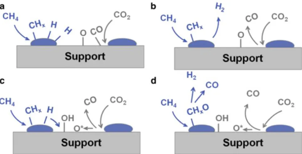
As the study on FTS developed in depth, more and more researchers have dedicated to the mechanical aspect and reaction pathway of FTS, while the mechanism of FTS is still regarded as complicated and debated. It has been widely accepted that FTS reactions at least involve a specific procedure including dissociative chemisorption of CO and H2 in the active sites of catalysts, chain initiation, chain growth, and chain termination. Based on these comprehensions, three widely recognized mechanisms for the activation of reactants and chain initiation are proposed as figures shown [24]: carbene mechanism (Figure 1-4), hydroxyl-carbene mechanism (Figure 1-5) and carbonyl insertion or carbon insertion mechanism (Figure 1-6), where the carbine mechanism is most widely accepted.
26
Figure 1-4. Scheme of carbene mechanism [24].
Figure 1-5. Scheme of hydroxyl-carbene mechanism [24].
Figure 1-6. Scheme of carbonyl insertion or carbon insertion mechanism [24].
The carbene mechanism initiates when the active sites of catalysts chemisorb H2 and CO and disperse on the active sites. After activation, the molecules of CO and H2 dissociate to form metal carbide, metal oxide and metal hydride on the surface. Then the metal oxide may react and combine with another molecule of activated H2 to produce hydroxyl group, which could be hydrogenated into water molecule then desorbed by catalysts. Meanwhile, the metal carbide can react with the vicinal activated hydrogen to produce the methylene groups, which is called the chain initiation process as the methylene groups are responsible for the propagation of long-chain hydrocarbons. CO2 desorbed by catalyst could be produced initially from the reaction of metal oxide and activated CO. For the hydroxyl-carbene mechanism, the
27 processes initiate with the chemisorption of CO molecules. H2 molecules in the atmosphere react with these sorbed CO molecular to form the carbinol groups. Then two vicinal carbinol groups can react with additional H2 molecules in the atmosphere to form long-chain oxygenates with desorbed water. The carbonyl or carbon insertion mechanism begins with the chemisorption and dissociation of H2 molecules at first. Then CO molecule could insert into the metal hydride to form formyl groups. After that, these formyl groups react with the H2 molecules in the atmosphere, meanwhile losing water molecules to form a methyl group, which is the chain initiation. Then the insertion reaction continues to result in chain growth.
Figure 1-7 and Figure 1-8 illustrate the chain growth process and chain termination process of FTS [19]. The formation of a methylene group is regarded as the chain initiation process, and it is widely accepted that the methylene group mainly takes responsibilities for chain growth. According to this mechanism, many researchers and publications defined the groups, which contribute most to chain propagation as -CHx pool or -CH2 pool. As shown in Figure 1-7, methylene groups combine with vicinal methylene groups, growing from the end to propagate the chain. Figure 1-8 describes the three main steps of the chain termination process. A hydrocarbon chain can be directly hydrogenated with H2 then desorbed. Besides, two vicinal chains can react and combine. Two possible reaction routes are proposed, one is an interaction between two chains to produce one H2 molecular and two olefins molecular, the other one is an interaction between one chain and the other (or methyl) to produce one olefin and one paraffin (or methane).
28
Figure 1-8. Chain termination process of F-T synthesis.
Although these mechanisms are very illustrative, there are still some debates and confusions about the in-depth mechanism of F-T reaction. During recent decades, steady state isotopic transient kinetic analysis (SSITKA) and quantum chemistry simulation have helped researchers to get better comprehensions on the detailed mechanism of FTS. Charles et al. [25] have done some SSITKA study on the chain growth process of FTS. They found direct evidence supported for a rapid chain growth, which was even much faster than the activation of CO on the surface of catalysts during FTS. This process appeared to require a rapid formation of monomers within diffusion distances of growing chains [25]. This conclusion was different from previous ideas that chain growth is a relatively slow process in FTS. Later, Frøseth’s research [26] and Yang’s works [27] showed good coincidence with the conclusion. Furthermore, it has been reported that a remarkable high energy barrier (~250 kJ/mol) was observed for the direct dissociation of C-O band on catalysts due to some publications of density functional theory simulation on FTS [28-32]. Theoretically, directly cleaving the C-O band was very difficult and unfavorable on the view of energy threshold during chemisorption. Therefore, the practical process of CO activation and dissociation is considered more complicated than previous ideas. Later a new pathway for the cleavage of C-O, which is called H-assisted route was
29 proposed. More and more evidence derived from experimental data and theoretical simulations showed that this pathway was more favorable during FTS process. Figure 1-9 derived from Manuel Ojeda’s work [29] demonstrated the individual energy barriers for every elementary step of CO dissociation and combination with other radicals on the surface of Co catalysts with 0.5 ML CO coverage. Apparently, the energy penalty of H-assisted pathway was lower than that of CO direct dissociation. These works implied that there should be two primary pools for the chain initiation: CHx pool and CH2O pool, all of which took the responsibilities for the following chain growth.
Figure 1-9. Individual energy barriers for elementary steps of CO the scission in the surface of Cobalt catalyst with 0.5 ML CO coverage by Manuel Ojeda [29].
According to these conclusions, one possible reaction pathway for H-assisted dissociation of CO is put forward:
𝐶𝑂 +∗ ↔ 𝐶𝑂∗ (8) 𝐻2+ 2 ∗ ↔ 2𝐻∗ (9) 𝐶𝑂∗+ 𝐻∗ ↔ 𝐻𝐶𝑂∗+∗ (10) 𝐻𝐶𝑂∗+ 𝐻∗ ↔ 𝐻𝐶𝑂𝐻∗+∗ (11) 𝐻𝐶𝑂𝐻∗+∗ ↔ 𝐶𝐻∗+ 𝑂𝐻∗ (12) 𝑂𝐻∗+ 𝐻∗ ↔ 𝐻2𝑂 + 2 ∗ (13) In these reactions, * indicates an active site of catalysts. Clearly, in H-assisted
30 dissociation pathway, the CH group can react with H to form CH2 group, which is the critical group for chain growth. So according to these works on the aspect of FTS mechanism, some important conclusions can be summarized:
1) Two common pools of monomer units (-CH2 and -CH2O) on the surface of catalysts that are responsible for the synthesis of hydrocarbons during FTS process.
2) Nature of catalysts, process conditions, and gas feed compositions that suppress hydrogen coverage favor the generation of long hydrocarbon chains. 3) FTS reactions are susceptible to the nature of catalysts due to the promotion
to different pathways with different energy barriers for CO dissociation. 4) Catalysts also significantly affect the final distribution of product
compositions.
1.3.2 Catalysts for FTS
As catalyst played a vital role in FTS due to its significant influences on the final product distribution, the later study on FTS was mainly focused on developing new and potent catalyst with its support. The general properties and principles which should consider are affordability, high activity, high selectivity to high hydrocarbons, and stable performance. Thus, the most critical variables of FTS catalysts are the selection of the metal precursor quantity of metal loading, selection of supports, and preparation with pretreatment methods. It has been widely reported that all metals of group VIII and some other alkali metals such as copper, zinc, and rhenium have
noticeably catalytic activity for FTS reactions [33]. Initially, Fisher and Tropsch had studied the performance of a Fe-Cu catalyst. Later more and more noble and non-noble catalysts were used and studied for FTS, among which ruthenium, iron, nickel, and cobalt were considered the most effective catalysts for the hydrogenation of carbon monoxide considering the performance and economic perspective. Currently, researchers mainly focused on the developments of Co and Fe-based catalysts due to their high activity, high stability and good selectivity rather than Ni, which is
31 considered extremely active to methanation or Ru, which is too expensive and not economical to industrial scale. Regardless of price, Co is found almost three times more active in the view of site basis than Fe due to some chemisorption analysis [34]. Moreover, Fe is highly active to WGS Reaction, which is undesirable during FTS and leads to the formation of the oxygenated hydrocarbons [35-37]. On the other hand, even cobalt catalysts do not exhibit significant WGS activity [37], water seems to have some positive effects on FTS process and the activity of cobalt catalysts depending on catalyst composition, nature of the support, catalyst preparation method and pretreatment [38]. Table 1-1 [39] shows a brief comparison between Co and Fe catalysts. Besides, both Co and Fe catalysts are extremely sensitive to sulfur, leading to contamination and deactivation. It has been reported that the sulfur components in the feed gas should be less than 0.1 ppm. Although Co catalysts are more active to methanation reaction at high temperatures than Fe catalysts, the selectivity towards C5+ hydrocarbons is remarkably 20%-30% more when using Co catalysts at relatively low temperatures. In total, because of the high hydrocarbon productivity, high stability, high conversion rate, cobalt catalysts are currently one of the most optimal and practical catalysts for the synthesis of C5+ hydrocarbons in FTS process and will continue to concentrate researchers’ focuses in the future.
Table 1-1. A brief comparison between Co and Fe catalysts [39].
parameter cobalt iron
cost and lifetime expensive but excellent resistance
to deactivation Cheap but short lifetime, easy to deactivation (coking, etc.)
activity higher activity and selectivity to
F-T synthesis lower activity and selectivity to F-T synthesis
WGS activity not significant high activity to WGS reaction
methanation activity high activity to methanation
32
flexibility more sensitive to reaction
condition, fewer flexibilities condition, more flexibilities less sensitive to reaction
Despite the catalysts, some researchers focused on the development of supports for catalysts. Active metallic catalysts deposited on higher surface area supports usually have higher contact area with the reactants, thus leading to more active sites for FTS reactions. It has also been widely reported that the structure of support affects the catalytic performance of catalysts due to its direct or indirect influences on the crystallite size, distribution, reduction, crystal structure of metal catalysts. Also, the diffusion behavior of the important reactive species in FTS process such as H is altered when introducing supports depending on their transport length, pore size, which could lead to a higher diffusion rate and contribute to the promotion of main reactions. Therefore, the design of supports is an essential part of the design of catalysts. Silica, alumina, and titania are the most common supports for Co catalysts.
Silica-supported cobalt catalysts, particularly silica aerogel supported cobalt catalysts, in general, exhibit high catalytic activity and liquid hydrocarbon selectivity in FTS process. Some notably physical and chemical properties of silica aerogel have been studied and confirmed to favor the main reactions of FTS such as: (i) high surface area which makes moderately high Co dispersion at relatively high loadings of Co [40-42], (ii) controllably wide range of pore size which ensures an excellent diffusion of gas components, and (iii) adjustable surface chemistry property which enables a high reducibility of metal [43]. Li et al. [44, 45] have researched the catalytic effects of Co loaded MCM-41, SBA-15, and SiO2 with different pore size. Their works showed that the mesoporous structure of SiO2 support could contribute to a moderate cobalt particle size and the highest dispersion of cobalt, which led to a high hydrogenation activity of CO. These results were in a good coincidence with Saib’s research [46]. Iglesia [47] has shown that water molecules, whether indigenous or additionally added to feeding reactants, increased the reaction rates of the reactants on Co/SiO2 catalysts. Furthermore, Li and Iglesia [48] again investigated the positive
33 effects of water on the CO conversion, olefin, and C5+ selectivity for silica-supported Co catalysts. The results complied with Das and his co-workers’ researches [49], in which they suggested that the addition of water in FTS process over a 12.4% Co/SiO2 (wt.%) catalyst led to a significant increase in CO conversion. Recently, Gunasooriya et al. [50] have investigated the possible elementary reactions based on Co catalysts in FTS process by DFT simulation. Their works revealed that surface hydroxyl groups on Co catalysts are found to be potent hydrogenating species for the conversion of CO during FTS process, which is accordant with the H-assisted dissociation mechanism mentioned above. Dunn et al. [51-55] have reported a series of researches on silica aerogel and xerogel supported nanocrystal Co catalysts for FTS process. They found all their mesoporous Co loaded silica aerogel catalysts were very active to the main reactions of FTS with good selectivity towards the C10+hydrocarbons. Danilo et al. [56] found that silica aerogel supported bimetallic Fe and Co nanocrystal catalysts have significantly high dispersion of metals and high thermal stability, which led to a remarkably high CO conversion (as high as 87%) at 200 °C. Besides, some researchers [46, 57-60] have revealed that the surface hydroxyl groups on the surface of silica formed during the preparation process could react with cobalt oxide to form cobalt hydroxide, which is extremely hard to be reduced. This negative interaction was also found common among the other catalysts with supports. However, for silica aerogel, it is possible to modify the hydrophobic surface property by introducing a hydrophobic group during preparation [61, 62].
Alumina and titania are also typical supports for FTS catalysts due to their high surface area, pore structure, and high dispersion of metals. Commonly, α-alumina and titania exhibit lower acidity than γ-alumina, which is assumed to be the reason for higher wax selectivity [63]. It was also widely accepted that the Brønsted acid sites should be more active than Lewis sites not only to FTS process, but also many other catalytic processes. However, to determine the kind of acid sites was not easy during preparation. Unlike SiO2 supports, hydrophobic modification of alumina and titania,
34 which results in the formation of difficultly reductive metal oxides. Moreover, it was found that in most cases a hydroxyl group in alumina supported catalysts played a negative role [64, 65] and water weakly affected the rate and selectivity of titania supported catalysts at high water concentrations [38, 48, 66]. Above all, Co loaded hydrophobic silica aerogel could be a very promising catalyst for FTS.
As FTS process has been successfully industrialized, Table 1-2 listed some of the applied industrial FTS processes since the 1930s with their applied technologies, reactors and catalysts [67]. The applied conditions of these processes varied from normal pressure (1 atm) and low temperature (< 250 °C) to high temperature (> 320 °C) and high pressure (up to 100 bar). With the in-depth of research, the later study and appliance are focused on the low-temperature or medium-temperature (~ 270 °C) but high-pressure processes to reach a considerable selectivity towards liquid paraffin and olefins. Variety types of FT reactor have been successfully carried out to industrial FTS process, including fixed bed, fixed or circulating fluidized bed, slurry bubble column, and so on. In industrial scale, Co and Fe are the most widely applied catalysts for not only hydrocarbon synthesis, but also the production of synthol.
Table 1-2. Industrial FTS processes since 1930s [67].
FT technology FT type FT reactor FT catalysts Built year
Normal-pressure synthesis Low temperature Fixed bed (tube
cooled) Co 1936
Medium-pressure
synthesis Low temperature Fixed bed (tube in tube) Co 1937
Hydrocol High temperature Fluidized bed
(fixed) Fe 1951
Kellogg Synthol High temperature Circulating
fluidized bed Fe 1955
Arge Low temperature Fixed bed
(multitubular) Fe 1955
Sasol Synthol High temperature Circulating
fluidized bed Fe 1980
Shell middle distillate
synthesis (SMDS) Low temperature (multitubular) Fixed bed Co 1993
Sasol Advanced Synthol (SAS)
High temperature Fluidized bed (fixed)
35
Sasol slurry bed
process (SSBP) Low temperature Slurry bubble column Fe 1995
Statoil slurry bubble
column process Low temperature Slurry bubble column Co 2005
Sasol slurry bed
process (SSBP) Low temperature Slurry bubble column Co 2007
High-temperature slurry FT process (HTSFTP) Medium temperature Slurry bubble column Fe 2008
1.4. A review on reforming CO
2with CH
4By coincidence, the dry reforming methane with carbon dioxide (DMR) was also first explored by Franz Fischer and Hans Tropsch in 1928 over Co and Ni catalysts [68]. According to their reports, a severe deactivation problem occurred due to the formation of carbon on the catalysts. Later in 1949, Lewis et al. [69] and Reitmeier et al. [70] reported different approaches to suppress the carbon deposition via the control of reactant composition, operating conditions and the stoichiometric amount of metal oxide supports respectively. Their study has helped to identify the conditions for reforming to suppress the deactivation issue. In 1964 and 1965, Rostrup-Nielsen first extensively explored and reported catalysts and their preparation process for the reforming of CH4 and higher vaporizable hydrocarbons [71, 72]. A co-precipitation process of a fine intimate mixture containing magnesium oxide, aluminum hydroxide, and nickel hydroxide was proposed. Up to a calcining temperature of 1100 °C, the conversion of alumina and part of the magnesia into spinel framework activated CO2 and promoted the oxidation of carbon on the catalysts. The concept that the introduction of basic metal oxide suppressed the deactivation then has been applied by the later researchers; however, the mechanism was not proposed. Subsequently, the research on reforming was more focused on the developments of catalysts with their supports and the catalytic mechanisms. Sodesawa et al. reported the reforming of CO2 with CH4 over a stable Ni/SiO2, where the carbon decomposition was remarkably
36 limited in 1979 [73]. Gadalla et al. studied detailedly on different Ni/Al2O3 catalysts and the effects of supports. They reported an optimum temperature range occurred for a different ratio of reactant component. In 1991, Ashcroft et al. tested a variety of noble-metal catalysts, including Pd, Ru, Rh, and Ir, and a high yield of syngas production was achieved [74]. Later various catalysts based on the noble and non-noble metals were tested, and their effects were studied [75-84]. Generally, non-noble metals such as Ir, Rh, Ru, Pt, and Pd, were found to exhibit high resistance to the unexpected carbon formation, despite the economic perspective, while non-noble alkali metals such as Ni, Fe, and Co were widely used for CO2 reforming with CH4. Thus, a small number of noble metals as promoters can be loaded along with the non-noble alkali metals, enhancing the dispersion, providing additional active sites, and improving the resistance to carbon formation. The influence of support, the promoters and the methods of preparation and activation were also investigated by many researchers [85-93], and several important points to improve the catalytic performance were proposed including the porosity, the dispersion, nature of promoters, the interaction between metals and supports and the active sites.
1.4.1 Reactions and thermodynamics
The primary reaction for CO2 reforming CH4 is extremely endothermic, requiring a large amount of energy for the products [94]:
𝐶𝑂2+ 𝐶𝐻4 → 2𝐶𝑂 + 2𝐻2, ∆𝐻2980 = 248 𝑘𝐽/𝑚𝑜𝑙 (14) As well-known, the molecules of CH4 and CO2 are stale, whose dissociation energy is 435 kJ/mol (for CH3-H) and 526 kJ/mol (for CO-O) respectively. It requires high temperatures to achieve reasonable equilibrium conversions to syngas products. Moreover, as the main reaction is extremely endothermic, a continuous heating supplement is essential. Similar to FTS, the equilibrium conversions of the production in CO2 reforming CH4 are also affected by the simultaneous occurrence of reverse water gas shift (RWGS) reaction, which generally leads to a higher conversion of CO2
37 than CH4:
𝐶𝑂2+ 𝐻2 → 𝐶𝑂 + 𝐻2, ∆𝐻2980 = 41 𝑘𝐽/𝑚𝑜𝑙 (15) Besides, some other additional reactions can occur continuously depending on the conditions, including operating temperatures, the ratio of reactants, and the nature of catalysts. Among those, the decomposition reaction of CH4 and the Boudouard reaction attribute to the formation of carbon deposition on the surface of catalysts, which leads to the deactivation of catalysts [95]:
𝐶𝐻4 → 𝐶 + 2𝐻2, ∆𝐻298° = 75 𝑘𝐽/𝑚𝑜𝑙 (16)
2𝐶𝑂 → 𝐶𝑂2+ 𝐶, ∆𝐻2980 = −172 𝑘𝐽/𝑚𝑜𝑙 (17)
Figure 1-10. Carbon containing product for the catalytic reactions: (a) CH4 decomposition (CH4 only),
(b) the Boudouard reaction (CO only), (c) CO2 reforming with CH4 (1:1). Adapted from [95], copyright
Elsevier.
The thermal equilibrium of these side reactions can be analyzed and determined by standard free energy at different temperatures. Wang et al. proposed that the equilibrium of the primary reaction proceeds in the forward direction when the temperature is above 640 °C [96]. Moreover, they also found that the decomposition of CH4 and the Boudouard reaction occur above 557 °C and below 700 °C, respectively, and the RWGS reaction only occurs up to 820 °C. Thus, they suggested an optimum temperature range of 870 to 1040 °C at a CO2/CH4 ratio of 1:1, reconciling the conversion and carbon formation [96]. Nikko et al. have conducted the thermodynamic equilibrium analysis on the multi-reaction system for carbon
![Figure 1-1. CO 2 emission by the combustion of fossil fuel from 2000 to 2014 [1].](https://thumb-eu.123doks.com/thumbv2/123doknet/2918241.76246/18.892.180.711.703.986/figure-emission-combustion-fossil-fuel.webp)