HAL Id: hal-01007104
https://hal.archives-ouvertes.fr/hal-01007104 Submitted on 9 Feb 2017
HAL is a multi-disciplinary open access archive for the deposit and dissemination of sci-entific research documents, whether they are pub-lished or not. The documents may come from teaching and research institutions in France or abroad, or from public or private research centers.
L’archive ouverte pluridisciplinaire HAL, est destinée au dépôt et à la diffusion de documents scientifiques de niveau recherche, publiés ou non, émanant des établissements d’enseignement et de recherche français ou étrangers, des laboratoires publics ou privés.
Distributed under a Creative Commons Attribution| 4.0 International License
New experimental sample for shear testing of adhesively
bonded structures
Georges Challita, Ramzi Othman, Pierrick Guégan, Khalid Khalil, Arnaud Poitou
To cite this version:
Georges Challita, Ramzi Othman, Pierrick Guégan, Khalid Khalil, Arnaud Poitou. New experimental sample for shear testing of adhesively bonded structures. International Journal of Modern Physics B, World Scientific Publishing, 2008, 22 (9 11), pp.1081-1086. �10.1142/S0217979208046359�. �hal-01007104�
NEW EXPERIMENTAL SAMPLE FOR SHEAR TESTING OF ADHESIVELY BONDED ASSEMBLIES
GEORGES CHALLIT A
Departement de Mecanique, Faculte de Genie Branche 2, Universite Libanaise, Beyrouth Liban.
RAMZI OTHMAN*, PIERRICK GUEGAN
Institut de Recherche en Genie Civil et Mecanique, Ecole Centrale de Nantes I rue de la Noe, BP 92101, 44321 Nantes cedex 3, France.
*ramzi. othman@ ec-nantes.fr
KHALID KHALIL
Departement de Mecanique, Faculte de Genie Branche 1, Universite Libanaise, Beyrouth Liban.
ARNAUD POITOU
Institut de Recherche en Genie Civil et Mecanique, Ecole Centrale de Nantes I rue de la Noe, BP 92101, 44321 Nantes cedex 3, France.
In this paper, Split Hopkinson Bar technique was used to investigate the shear behaviour of adhesively bonded assemblies at high rates of loading. New sample geometry was adopted so that the compressive wave is transformed in a shear loading in the sample. Samples are conditioned at 20°C and 50% of hygrometry to eliminate any interference with temperature and humidity effects. The new technique is applied to an assembly built with a cyanoacrylate based adhesive and a metallic (Steel) adherent. They are found to be highly rate sensitive.
Keywords: Hopkinson bar; adhesively bonded assembly; shear; in-plane load; high strain rate.
1. Introduction
The use of adhesively bonded assemblies is widespread mainly in aeronautic, automotive and electrical engineering. This is due to many assets such as low cost and manufacturing flexibility. In these applications, the adhesive joints can subdue impact loads as well as quasi-static loadings. Therefore, it is of major concern to measure the sensitivity of the mechanical properties of these joints to the loading rate. Multiple quasi-static tests are specified in the ASTM standards.' Only few investigations were carried out on the impact
response of these assemblies. Zachary and B urger2 and Rossamanith and shukla3
a1.4 investigated their fracture energy using a three-point bending specimen. Sato5 studied the absorbed energy in a CFRP-aluminium alloy beam. Lawrence Wu et a1.6 used the Hopkinson bar technique to measure the absorption energy of electronic adhesive joints. Nonetheless, non of these studies did measure the strength of the joints.
Harris et al.7 proposed an impact where the shear strength of a single-lap joint is measured. However, only low-impact velocity of 1.34 m/s is reached. Lataillade et al. proposed the use of the Hopkinson bar technique8-9 and a tensile technique with an inertial wheel10 to achieve much higher impact velocities. Bezemer et aL11 used a rod-and-ring specimen impacted by a drop-weight system and a compressive air gun. In line with 8, Yokoyama and Shimizu12-13 and Srivastava et al.14 determined the impact shear strength using a modified split Hopkinson bar. A new sample geometry was used. A pin-and-collar specimen was proposed in12 and double-L specimen was considered in.14 The impact velocity can reach 20m/s in these techniques. Different loading configurations were also investigated. The tensile strength of adhesive joints was investigated15-19. Sato and lkegami20-21 used Hopkinson bar technique to apply a combined tension-torsion load. In this paper, we are interested in the measurement of the shear strength of adhesively bonded joints. We will use the Hopkinson bar technique because it takes into account the wave propagation in the experimental set-up. However, the specimen geometries, proposed in literature, yield an impedance mismatch with the bar. The incident wave, induced in the input bar by the strike of the projectile, reflects in this bar before reaching the adhesive joints. In the same way, the transmitted wave, through the adhesive joint, reflects before reaching the strain gauge cemented on the output bar. This can alter the input and output force measurements. A new M-shaped specimen is proposed. It consists of a double lap adhesive joint.
2. Experimental Set-Up 2.1. Hopkinson bar apparatus
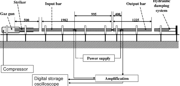
The conventional configuration of the Hopkinson bar technique22 consists of two elastic bars (Fig. 1). One gauge station is cemented on each bar. A compressive wave is generated by the impact of striker on the input bar. This incident wave moves through the input bar till the bar-specimen interface. At this interface, a first part of the wave is reflected back into the input bar as a tensile wave and a second part is transmitted through the specimen into the output bar as a compressive wave. The input gauge station measures the incident and reflected waves and the output gauge records the transmitted wave. The input gauge is cemented in the middle of the input bar and the striker length is taken less than half the input bar length. In this case, the incident and the reflected waves are recorded separately with the input gauge. Assuming one-dimensional wave propagation, the force applied by the bars on the specimen are given by:
(1 b)
where the subscripts in. out• inn r(f and rra mean input bar, output bar, incident wave,
reflected wave and transmitted wave, respectively, and A is the cross-section area, E the
Young's modulus, t: is the wave's strain.
Striker I I I I I I Compressor Digital storage oscilloscope Power supply Output bar \ \ \ \ \ Amplification
Fig. 1. Simplified Scheme of the Hopkinson bar apparatus.
2.2. Specimen geometry
Hydraulic damping
system
The specimen consists of three adherent plates bonded by two adhesive layers (Fig. 2).
The middle adherent plate is shifted from the two others. It is aligned with the output bar
end. Whereas, the lower and the upper plates must be aligned with the input bar end. The specimen can be easily sandwiched between the two bars without any modification on the conventional configuration. The mechanical impedance of each adherent plate is constant to not induce any undesired reflex ion of the waves. The in-plane movement of the bars is transformed by the geometry of the specimen to a shear loading on the adhesive layers. Assuming dynamic equilibrium in the specimen, the shear stress is deduced from the input and output forces as follows:
r(t)
=~n
(t
)+
Fout(t)
4Aadh
(2)
where Aadh is area of a single-lap joint.
2.3. Specimen preparation
To ensure the good alignment of the specimen a special mounting device is developed
(Figs. 3). To prepare the specimen, the following steps are followed:
(1) The three adherent plates are deburred with an abrasive paper P220.
(2) The faces of the adherent plates are polished with paper P220.
(3) The adherent plates are wiped with dry paper.
(a)
Fig. 2. Specimen Geometry: (a) side sight (b) rear sight.
(a) ! -•1 °Fapcpeerof Screw , I -,./ · ·· • ">., ! 1
,...
J.-f
lower "N,·_ . , _ _ _ ... .~("'_· __,! ! plate rE::Jc____.,.,..._. _ ____,I ! = '~. I ; ... ! Mounting --~., ""'-{, Lower .__; _ _ _ _ _ ___,! "'-· Plate (c) Screws Mounting ; ' i' Upper ! !/"' Plate ~~r , - - - , . , " " ' 1' ; ,.-/'~, f - ' - - - - , - - - ' - - , - - j '-;..; 1--r--+---'-i Screw;
I
~
I -~...
l
'l,
....
; 1 ! Middle Plate Lower Plate (b) Middle Plate Screw Mounting .,__, (d) MountingFig. 3. Specimen preparation, bonding steps.
(b) 3.0 Screw Lower Plate ! Pressure ~, <~-+)---+-+-- Screw Specimen
(5) The adherent plates and the mounting device are cleaned with acetone.
(6) The adhesive is spread on the upper face of the lower plate, this plate is then fixed by a screw in the mounting device as shown in Fig.3a.
(7) The adhesive is spread on both faces of the middle plate, this plate is then fixed by a screw in the mounting device in the opposite side of the first screw to create the gap between the two plates, as shown in Fig.3b.
(8) The adhesive is spread on the lower face of the upper plate, this plate is fixed by a
screw in the mounting device in the same side of the first screw, as shown in Fig.3c.
(9) The whole specimen is then fixed in the mounting device by a vertical pressure screw to keep a constant pressure and ensure a convenient adhesion between the three plates, as shown in Fig. 3d.
( 1 0) The specimen is cured at room temperature for 24 hours.
( 11) The specimen is kept in a conditioned room (local temperature 20°C, relative hygrometry 50%) for at least one week.
(12) The specimen is tested at room temperature after no more than two hours from getting it out from the conditioned room.
3. Experimental Results
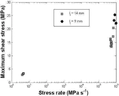
For high rate of loading, a steel Hopkinson bar is used (Fig. 1). The bars are 16mm in diameter. The Young's modulus is 190GPa. The elastic limit is 1400MPa. The specimen is made of three steel (35NCD16) plates bonded by a cyanoacrylate based adhesive (261 0). The adhesive layer is 20f.!m
+
8f.!m. The strain measurements are recorded at a frequency rate of 1 OMHz. The force at the two specimen-bar interfaces are computed using the software DAVID23 developed at the Ecole Polytechnique (France). Then, the shear strength is deduced using Eq. (2). The same geometry is tested with a conventional quasi-static machine to compare the impact shear strength with the quasi-static values. Fig. 4 shows the variation of the shear strength with the mean value of the shear rate. The shear strength is found highly rate-sensitive. A bilinear behavior is observed. In fact the gradient increases considerably at high rates (greater than 5 105 MPa s-1 ). Two joint overlap lengths (lj : see Fig. 2) are tested (9 and 14 mm). The results obtained with the short specimens confirm the bilinear behavior.' ·
••••
·~·
:::o:.~~~~:.J.'~:~:':.Jnf: ! :'':·~: 11:d: · :! -~'- ':':~~.. _· .:-':-:--l.; .. ,.LL;l.J:
1d . 101 102 16' td4 ..
td
5 . .1d$tre~s•'
.
rate
•
•
{MPa,.st
1)Fig. 4. Variation of the shear strength with the loading rate.
4. Conclusion
In this paper, new sample geometry was tested by the Hopkinosn bar technique. The influence of the loading rate on the shear strength of double-lap adhesive joints was investigated. The advantage of the new geometry is that it minimizes the impedance
mismatch with the bar. Moreover, a mounting device is developed to ensure the good alignment of the specimen with the two bars.
Acknowledgments
The authors want to Franc Pasco, Luc de Pin, Alexandre Duchene, Jose Maria Bian for their help in the experimental work.
References
1. 1995 Annual Book of ASTMStandards, Vol. 15.06, adhesives, ASTM, (1995), Philadelphia. 2. L.W. Zachary, C.P. Burger, Exper. Mech. 20, 162 (1980).
3. H.P. Rossamanith, A. Shukla, Ingenieur-Archive 51,275 (1981). 4. A. L. Kinloch, G. A. Kodokian, J. adhesion 24, 109 (1987). 5. C. Sato, Journal de Physique IV 110, 747 (2003).
6. C.M. Lawrence Wu, R.K.Y. Li, N.H. Yeung, J. Electronic Packaging, Trans. ASME 125, 93 (2003).
7. J. A. Harris, Proceedings Institute Mech. Eng. 199, C2 (1985).
8. J.L. Lataillade, C. Keisler, Ph. Charobonnet, Preptints of EURADH'92 Conference
(Karlsruhe, Germany), (1992), pp. 584-589.
9. C. Keisler, J.L. Lataillade, Journal of Adhesion Science and Technology, Vol. 9, (1995), pp. 395-411.
10. F. Cayssials, 1 .L. Lataillade, J. adhesion 56, 281 (1996).
11. A.A. Bezemer, C.B. Guyt, A. Vlot, Int. J. Adhesion Adhesive 18, 255 (1998). 12. T. Yokoyama, Key Eng. Mater. 145-149,317 (1998).
13. T. Yokoyama, H. Simizu, JSMEint. J. SeriesA 41,503 (1998).
14. V. Srivastava, A. Shukla, V. Parameswaran, J. Testing Evaluation 28, 438 (2000).
15. T. Yokoyama, International Conference on advanced Technology in Experimental
Mechanics, Vol. 2, 21-24 July 1999,366 (1999).
16. T. Sawa, Y. Suzuki, I. Higuchi, Impact Engineering and Application. Proceedings of the 4th International Symposium on Impact Engineering. Ed. A. Chiba & S. Tanimura. Elsevier Science Ltd., 469 (2001).
17. T. Yokoyama, J. Strain Analysis Eng. Design 38, 233 (2003). 18. T. Yokoyama, K. Nakai, Journal de Physique IV 134, 789 (2006).
19. H. Wada, K. Suzuki, K. Murase, T.C. Kennedy, Impact Engineering and Application. Proceedings of the 4th International Symposium on Impact Engineering. Ed. A. Chiba & S.
Tanimura. Elsevier Science Ltd., 463 (2001). 20. C. Sato, K. Ikegami, J. adhesion 70, 57 (1999).
21. C. Sato, K. Ikegami, Am. Soc. Mech. Eng., Design Engineering Division, Vol. 105, 139 (1999).
22. H. Kolsky, Proceedings of the Physical Society B, Vol. 62,( 1949), pp. 676-700. 23. G. Gary, V. DeGreff, DAVID User Manual.