HAL Id: hal-02863894
https://hal-mines-albi.archives-ouvertes.fr/hal-02863894
Submitted on 24 Jun 2020
HAL is a multi-disciplinary open access
archive for the deposit and dissemination of
sci-entific research documents, whether they are
pub-lished or not. The documents may come from
teaching and research institutions in France or
abroad, or from public or private research centers.
L’archive ouverte pluridisciplinaire HAL, est
destinée au dépôt et à la diffusion de documents
scientifiques de niveau recherche, publiés ou non,
émanant des établissements d’enseignement et de
recherche français ou étrangers, des laboratoires
publics ou privés.
Heat treatments design for superior high-temperature
tensile properties of alloy 625 produced by Selective
Laser Melting
Jiwon Lee, Mathieu Terner, Sunyoung Jun, Hyun-Uk Hong, Etienne Copin,
Philippe Lours
To cite this version:
Jiwon Lee, Mathieu Terner, Sunyoung Jun, Hyun-Uk Hong, Etienne Copin, et al.. Heat
treat-ments design for superior high-temperature tensile properties of alloy 625 produced by
Selec-tive Laser Melting. Materials Science and Engineering: A, Elsevier, 2020, 790, pp.1-15/139720.
�10.1016/j.msea.2020.139720�. �hal-02863894�
Heat treatments design for superior high-temperature tensile properties of
Alloy 625 produced by selective laser melting
Jiwon Lee
a,b, Mathieu Terner
a, Sunyoung Jun
a, Hyun-Uk Hong
a,*, Etienne Copin
b,
Philippe Lours
b,**aDepartment of Materials Science and Engineering, Changwon National University, 20 Changwondaehak-ro, Changwon, Gyeongnam, 51140, Republic of Korea bInstitut Cl�ement Ader (ICA), Universit�e de Toulouse, CNRS, IMT Mines Albi, INSA, ISAE-SUPAERO, UPS, Campus Jarlard, F-81013, Albi, France
Keywords: Superalloy
Selective laser melting Heat treatment Tensile properties Grain boundary serration
A B S T R A C T
The popular superalloy Alloy 625 was produced by Selective Laser Melting (SLM) and post-processing heat treatments were designed to optimize the inhomogeneous and constrained as-built microstructure (AB) for high temperature structural applications. A single-step solution heat treatment (RX) was designed to promote full recrystallization and approach the conventional wrought microstructure. To enhance high temperature prop-erties, a grain boundary serration heat treatment (GBS) was successfully designed involving higher solution temperature and time to promote recrystallization and homogeneity, and a direct slow cooling step followed by a short aging to assist solute diffusion and grain boundary motion. The resulting microstructures were charac-terized by fully recrystallized fine equiaxed grains and fine intra and intergranular NbC precipitates. The GBS alloy also exhibited as much as 80% of serrated grain boundaries with enhanced resistance to cracking at high temperatures. Tensile properties of all three materials were evaluated at room temperature, 500 �C, 600 �C and 700 �C and compared with their conventional solutionized wrought Alloy 625 counterpart (Wrought). While the AB material exhibited high strength and low ductility, due for the most part to the high density of tangled dislocations resulting from SLM, both RX and GBS alloys showed tensile properties comparable to the conven-tional wrought material, higher strength in particular. At all temperatures, all four alloys exhibited yield strength values well over 200 MPa. Due to significantly different microstructures, deformation and fracture behaviors were different. While Wrought clearly presented irregular plastic flow at elevated temperatures typically attributed to dynamic strain aging (DSA), the materials produced by SLM and moreover those subjected to post- processing heat treatments exhibited more stable plastic deformation. The results and characterization reported in the present article highlight the predominant role of microstructure and outstanding potential of SLMed Alloy 625.
1. Introduction
Alloy 625 is an attractive Ni-based superalloy for marine, chemical, aerospace and power generation applications where superior mechani-cal properties are required. Relatively high contents of Cr, Mo and Nb provide good corrosion resistance and solid solution strengthening. Although this alloy is intended as a solid solution strengthened alloy, several precipitates may form either in service or during a designed age- hardening treatment. Nb in particular promotes the precipitation of fine γ00(Ni
3Nb) particles and Nb-rich MC carbides [1–4]. The strengthening
effect of γ00precipitates comes from their coherency with the γ-matrix
and the distortion caused by the c-axis of their tetragonal structure, however precipitation kinetics is low [5–7]. This alloy is recognized for exhibiting good strength and ductility, as well as good resistance to creep and rupture at high temperatures. These attractive attributes for materials design however compete with good manufacturability: application of Alloy 625 is limited due to excessive tool wear or in other words low material removal rate, which makes conventional machining difficult after forging [8,9].
The blasting emergence of Additive Manufacturing (AM) technolo-gies in the past decade seems to address this issue. AM enables near net shape production of complex geometries with very limited tooling and is
* Corresponding author. ** Corresponding author.
leading the 4th industrial revolution as an outstanding alternative to conventional manufacturing methods. Due to its excellent weldability, Alloy 625 is an excellent candidate for the now-well-known Laser Powder Bed Fusion (LPBF) process or otherwise known as Selective Laser Melting (SLM). A large number of studies have addressed different aspects of the fabrication of Alloy 625 by SLM from microstructure optimization to mechanical responses [10–14]. Strength and ductility in particular are critical mechanical properties for structural applications and have therefore been studied accordingly. Yadroitsev et al. studied the effect of processing conditions, in particular specimens orientation, on tensile properties [11]. Hack et al. compared several SLMed Alloy 625 conditions to conventional standards [12]. Marchese et al. studied the effects of various heat treatments and resulting microstructures [13]. Tian et al. recently published a review on Alloy 625 produced by SLM including tensile properties results [14]. Most research agree that additively manufactured Alloy 625 by SLM exhibits strength and elon-gation properties similar or better than its conventional wrought coun-terpart, and that these properties strongly depend on the microstructure of the alloy. These studies on tensile properties are however mainly focused on room temperature behavior although this alloy is clearly designed for high temperature applications. High temperature tensile properties are therefore needed to appropriately assess its potential and possibly optimize the performance of the alloy when produced by SLM. It exists several methods to further enhance the high temperature properties of heat resistant metallic alloys. These include careful opti-mization of the processing conditions to control defects or rigorously designed heat treatments to command microstructure. Grain Boundary Serration (GBS), characterized by the formation of wavy or zigzag grain boundaries which can be triggered by specifically designed heat treat-ments, has been found particularly efficient to improve high tempera-ture resistance – creep and crack propagation in particular – of low-γ0Ni-
based superalloys [15–20]. The authors recently designed a specific continuous heat treatment including slow cooling between solution and aging temperature which successfully led to GBS in a wrought Alloy 625 [21]. This heat treatment was modified to be applied to the alloy pro-duced by SLM considering its peculiar microstructure. The present study consequently describes the elaboration of this GBS heat treatment and compares the resulting high temperature tensile properties in the range 500 �C–700 �C to those of a standard wrought Alloy 625 (Wrought), an
as-built (AB) SLMed Alloy 625 and an SLMed Alloy 625 subjected to a solution heat treatment to promote full recrystallization (RX). The re-sults highlight the predominant role of microstructure and outstanding potential of SLMed Alloy 625.
2. Materials and methods
2.1. Raw materials
The wrought Alloy 625 used in this study was a standard hot rolled material with nominal chemical composition Ni–22Cr–9Mo–3Fe–4Nb (in wt.%) and solution treated at 1150 �C/1hr. Gas-atomized Alloy 625
powder suitable for SLM production was provided by the machine manufacturer. The element composition of the powder, Ni–22Cr–9Mo–3Fe–3.5Nb (in wt.%), was close to that of the wrought material and satisfied the standards. Most particles were spherical with a typical size distribution measured with a laser particle size analyzer between D10 ¼20 μm and D90 ¼44 μm and an average diameter of 29 μm. Samples were produced with a commercial SLM 125HL machine by
SLM Solutions. A stripe scanning strategy with a 33�rotation between
layers was used and default optimal parameter conditions for Alloy 625 were utilized (laser power P ¼ 275 W, scanning speed v ¼ 760 mm/s, hatching distance h ¼ 120 μm and layer thickness t ¼ 50 μm)
corre-sponding to an energy density of 60.3 J mm 310 � 10 � 10 mm3 cubes
were produced to analyze the as-built microstructure and to optimize heat treatment conditions. 74 mm long cylindrical specimens with a 15 mm diameter were also produced vertically to be machined into
standard tensile test specimens. With these default processing condi-tions, the residual porosity measured by microscopy [22] was slightly lower than 0.5%, consisting mainly in small spherical pores from entrapped gaz. Among other assets, the SLM process is acclaimed to allow production of nearly fully dense materials. Thorough optimization of the process parameters has led to very low amount of residual porosity well below 0.1% [9,23,24]. Although this was beyond the scope of the presently reported study, this suggests that the SLM fabrication of Alloy 625 may be optimized to reduce further the already very low porosity and consequently enhance mechanical properties.
2.2. Heat treatments
Four Alloy 625 conditions were considered in the present study: i) conventionally wrought (Wrought), ii) as-built SLMed (AB), iii) SLMed followed by a recrystallization heat treatment (RX) and iv) SLMed fol-lowed by a specifically designed heat treatment for grain boundary serration (GBS). Design of the heat treatments is discussed in detail in section 3.2. The recrystallization heat treatment consisted in heating as- built material to 1200 �C for 1 h followed by air cooling to room
tem-perature to avoid stress build up and possible cracking at higher cooling rate such as for water quenching. The grain boundary serration heat treatment consisted in heating as-built material to the higher tempera-ture of 1300 �C for 90 min followed by slow cooling at the controlled
cooling rate of 5 �C/min down to the aging temperature of 870 �C at
which the material was maintained for 2 h before air cooling to room temperature. All heat treatments were conducted in air using a Marshall box furnace equipped with a programmable controller to precisely control temperature, time and cooling rate.
2.3. Tensile tests
Specimens for tensile tests were prepared by machining to standard round shape with a gauge length of 25 � 0.1 mm and a diameter of 6.0 � 0.1 mm [25]. The tensile direction was parallel to the building direction (z direction) for the SLMed materials and parallel to the rolling direction for the wrought material. All four material conditions were tested at room temperature, 500 �C, 600 �C and 700 �C using a cross-head speed
of 1.5 mm/min (strain rate of 1 � 10 3 s 1) for room temperature and of 0.5 mm/min (strain rate of 3.3 � 10 4 s 1) for high temperatures,
respectively. An electromechanical tensile test machine was used for all measures (MTDI, UT100F, 10 tonf). The temperature was raised to the test temperature by a sealed furnace at 30 �C/min and a 30 min soak
time was considered for homogeneity and stability. Although only one result was considered for each condition, all tensile tests were repeated twice and no significant difference was noticed. It should be noted that the values of yield strength (YS in Fig. 5) were carefully measured ac-cording to the Rp0.2 method [25], which is often challenging at high
temperatures. The reported values are therefore approximations with a confidence of about � 3 MPa.
2.4. Microstructure analysis
Specimens for microstructure analyses were sectioned, hot mounted in phenolic resin and conventionally ground with SiC abrasive papers followed by sequential polishing with diamond paste down to 1 μm. The
microstructure was revealed by means of a 100 ml HCl þ 0.5 g CrO3
etching solution and investigated by optical microscopy (OM, OLYMPUS BX51 M) and Scanning Electron Microscopy (SEM, JSM-6510) equipped with energy dispersion X-ray spectroscopy (EDS). Electron backscat-tering diffraction (EBSD) with a field-emission scanning electron mi-croscope (FE-SEM, MIRA-II) was carried to evaluate grain size in particular. To avoid artifacts from metallographic preparation, the final 1 μm polishing step was carried out using a colloidal silica suspension.
Electron probe micro-analysis (EPMA, CAMECA SX-100) was also car-ried out prior to etching in order to investigate the element distribution
and highlight segregation in the AB material. Specimens for trans-mission electron microscopy (TEM, field-etrans-mission type JEOL JEM- 2100F operating at 200 kV) equipped with Energy Dispersive X-ray Spectroscopy (EDS) were extracted from the vicinity of the fracture surface after tensile test at 700 �C and from the AB material. Thin foils
were prepared by fine grinding and polishing to a thickness of approx-imately 200 μm, punching of 3 mm diameter discs and electropolishing
to perforation with a 200 ml perchloric acid þ 800 ml methanol solution at 26 �C ~ 28 �C using a jet polisher (Struers TenuPol-5) operating at
50 mA and 25 V.
3. Results and discussion
3.1. Initial microstructure of raw materials
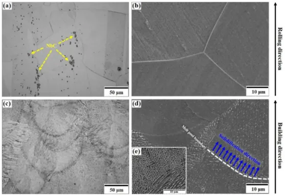
The microstructure of the conventional solutionized wrought mate-rial is shown in Fig. 1(a) and (b). It consisted in a fine fully-recrystallized equiaxed microstructure, with a grain size measured by electron back-scattered diffraction (EBSD) of approximately 130 μm and primary Nb-
rich MC carbides precipitated during solidification and often distributed along the rolling direction. This was typical of the standard wrought Alloy 625 characterized by a single phase FCC γ-matrix where alloying elements are homogeneously distributed in solid solution and no other phase other than primary MC carbides are detected. A corresponding hardness value of 206 Hv was measured.
The microstructure of the as-built material produced by SLM (here-after referred to as AB), in Fig. 1(c) and (d), was characterized by a very fine cellular/dendritic structure with grains intercepting several melt pools elongated along the building direction. This peculiar microstruc-ture is typical of alloys produced by AM powder bed fusion processes such as SLM. As the high energy laser beam travels over a layer of powder deposited according to the layer-by-layer production sequence, the high heat input not only causes local melting of the powder but also partial remelting of the underlying consolidated material. As a result, solidification as the laser beam moves away proceeds in the opposite direction of the heat transfer. Furthermore, due to the partial remelting of the underlying material, grains formation is characterized by epitaxial
solidification therefore leading to the observed textured microstructure, often referred to as columnar, where grains intercept several melt pools despite the interrupted solidification process. The very fine cellular/ dendritic structure is the result of the very high solidification rate due to the rapid scanning of the laser beam (here 760 mm/s). The inset in Fig. 1
(d) highlights this very fine cellular/dendritic structure. The cooling rate
εc can calculated as a function of the primary dendrite arm spacing λ1,
which was systematically measured between approximately 0.7 and 2
μm in several locations. The following equation (1) is generally accepted
[10,26–33]:
λ1¼a �εc n (1)
where λ1 is the primary dendrite arm spacing in μm and εc is cooling rate
in �C/s. The constants a and n are materials constants and their values
are not clearly available from the current literature for Alloy 625 [26–33]. Nevertheless, computations gave an approximation of the cooling rate of 105–106 �C/s, which is consistent to reported values for SLM [10,13,26–28,34]. The either cellular or dendritic nature of the microstructure is still debated. It has been clearly established that the SLM process occurs under rapid solidification conditions, as just demonstrated. Moreover, it seems clear from the microstructure and it was otherwise confirmed that the cooling rate in SLM is not constant [35]. It becomes a common opinion that the inconsistent rapid solidi-fication taking place during SLM processing oscillates between the for-mation of high velocity cells and fine dendrites, as both microstructural features are often observed.
The rapidly solidified AB microstructure is also characterized by inhomogeneous distribution of the constituting elements of Alloy 625.
Fig. 2 shows the EPMA results clearly highlighting significant segrega-tion of Nb and C, and to a lesser extent Mo, within the intercellular/ interdendritic regions. As it is clear from the contrast in SEM micro-graphs (Fig. 1(d)), the heavily segregated microstructure of multi-constituent alloys produced by SLM and in particular Alloy 625 has been often reported. In particular, it was found that such segregation modifies the precipitation behavior of Alloy 625. Marchese et al. [13] for example observed inhomogeneous precipitation of the γ00-Ni
3Nb phase after
direct aging in absence of a solutionizing step, which was attributed to
Fig. 1. Micrographs showing the (a) OM and (b) SEM microstructure of the conventional wrought Alloy 625 (Wrought); and the (c) OM and (d) SEM microstructure of the as-built (AB) Alloy 625 produced by SLM.
the inhomogeneous distribution of Nb. Lindwall et al. [34,35] used simulation tools to model segregation and explain in particular the more rapid precipitation kinetics of the δ-phase with respect to wrought Alloy 625.
The finer features of the typical AB microstructure were evidenced by the high magnification TEM micrographs in Fig. 3. The microstruc-ture was characterized by the very fine cellular/dendritic strucmicrostruc-ture exhibiting high dislocations density particularly within the interden-dritic areas and the presence of very fine precipitates with a size �50 nm. A corresponding hardness value of 314 Hv was measured, much higher than that of its wrought counterpart. The high density of dislo-cations is indicative of accommodation for residual thermal stress due to the rapid cooling and heating cycles inherent to the SLM process and illustrates the high levels of residual stress. So much so that average misorientation maps obtained by EBSD have often been used to eval-uate, to some extent, residual stress in materials built by SLM [36]. Fine precipitation similar to that observed in Fig. 3 (a) and 3(b) has been previously reported [7,13,14,23,27,34]. These precipitates are primar-ily aligned along intercellular/interdentridic areas (Fig. 3(b)) due to significant segregation of Nb and C as previously mentioned (Fig. 2), though precipitation within cellular/dendritic cores has also been observed as pointed by arrows in Fig. 3(a). Evidenced by the selective
area diffraction pattern (SADP) in Fig. 3(c), these coherent NbC carbides formed during solidification by the eutectic reaction L → γ þ MC. Although this reaction essentially takes place within intercellular/-interdentridic regions, the very high cooling rate characteristic of SLM processing promotes solute trapping within cellular/dendritic cores thereby advocating the presence of the fine NbCs. Their coherency with the γ-matrix was confirmed by SADP showing the orientation relation-ship defined by {200}NbC//{200}γ-matrix, [001]NbC//[001]γ-matrix.
3.2. Design of heat treatments and resulting microstructures 3.2.1. Recrystallization heat treatment (RX)
In the attempt to enhance the mechanical behavior of Alloy 625 produced by SLM, two heat treatments were specifically designed to convert the highly segregated, textured and constrained AB micro-structure (section 3.1) into a more homogeneous recrystallized micro-structure for high temperature applications. The first heat treatment was defined as the recrystallization heat treatment (hereafter referred to as RX) and was an attempt to produce microstructural features resembling those of the conventional wrought and solutionized microstructure (Fig. 1(a) and (b)). For SLM processed materials, it is often found that recrystallization can be promoted by a sole heat treatment step at high
Fig. 3. TEM micrographs of the AB material: (a) high magnification showing high dislocations density and intracellular/intradendritic precipitation of NbC carbides (arrows) and (b) details of the squared region in (a) highlighting intercellular/interdendritic precipitation of NbC carbides within intercellular/interdendritic regions (arrows). SADP in (c) demonstrates the coherency of NbC with the γ-matrix ({200}NbC//{200}γ-matrix, [001]NbC//[001]γ-matrix).
enough temperature, in absence of any mechanical operation such as cold or hot working and without the assistance of hot isostatic pressing [36]. This may be attributed to the high density of dislocations discussed previously (Fig. 3(a)), a sign of the high energy stored within the AB material. Accordingly, the recrystallization temperature range typically corresponds to the usual solution temperature range. Recrystallization of Alloy 625 produced by SLM has been reported in several studies after solution treatments between 1100 �C and 1250 �C for 0.5–2 h [13,14,36,
37]. In the present investigation, the RX heat treatment consisted in a solution treatment at 1200 �C for 1 h, followed by air cooling to room
temperature (Fig. 4(a)).
The resulting microstructure is displayed in Fig. 4(b) and (c). The RX material exhibited fully recrystallized equiaxed grains with an approx-imate grain size of 80 μm, significantly lower than that of the wrought
material (130 μm). The micrographs in Fig. 4(b) and (c) clearly
high-lighted the large amount of fine globular precipitates all over the ma-terial. A large amount of submicrometer particles appeared to be homogeneously distributed within the γ-matrix (solid blue arrows), together with relatively larger particles with a size � 3 μm (dashed
yellow arrows). The larger particles, within the SEM-EDS detection range, were clearly identified as NbC carbides. Although the finer pre-cipitates could not be definitely identified and require finer analyses, all evidences point to the conclusion that these were also fine NbC particles. According to the standard TTT diagram for Alloy 625 [3], the temper-ature of 1200 �C is well over the precipitation range of MC particles.
Primary NbC formed during solidification are however consistently observed and the start precipitation temperature reported for Alloy 625, promoted by the rather high Nb content, is 1250 �C [38]. This is
consistent with the very fine NbC carbides precipitation clearly observed within the AB material (Fig. 3). It is therefore reasonable to assume that the temperature of 1200 �C is not sufficient to dissolve the primary NbC
carbides which not only remained after solutionizing for 1 h but also seemed to coarsen (Fig. 4(c), dashed yellow arrows). However, regarding the finer MC precipitated (solid blue arrows), it is not clear whether they resulted from the nucleation of secondary MC carbides or only from coalescence of the very fine primary carbides of the AB con-dition. Similar NbC precipitates have been reported in Alloy 625 pro-duced by SLM and submitted to solution treatments [13,14,27]. There was no evidence of precipitation of any other phase in the RX material. A corresponding hardness value of 231 Hv was measured, 26% lower
compared to the AB state but slightly larger than that of the Wrought sample.
3.2.2. Grain boundary serration heat treatment (GBS)
The second heat treatment was specifically designed for promoting grain boundary serration, hereafter referred to as GBS. As mentioned in introduction, grain boundary serration is an effective way to strengthen grain boundaries and consequently enhance properties such as creep and crack propagation resistance of solution strengthened Ni-based su-peralloys at high temperature [15–20]. While the beneficial outcome is not debated, opinions diverge on the driving force and the mechanism for the formation of serrated grain boundaries. Several models describe this phenomenon as an interaction between grain boundary precipitates and grain boundary motion [39–41]. This is however in contradiction with some of our more recent observations where serrated grain boundaries developed spontaneously prior to the formation of pre-cipitates [17,18,42–47]. Moreover, the authors recently reported the occurrence of grain boundary serration in a Ni–20Cr model alloy inherently devoid of any second phase [48]. Observations led to the conclusion that grain boundaries may spontaneously assume a serrated morphology, promoted by lattice strain energy built up in their vicinity as a result of solute diffusion and segregation during slow cooling from solution to aging temperatures, in order to decrease their energy by accommodating the misoriention between adjacent grains [44,49,50]. This model was defined as the strain-induced grain boundary serration model. Based on this model, the authors have reported the possibility to induce grain boundary serration in a wrought Alloy 625 similar to the conventional wrought material used for comparison in the present investigation [21].
The GBS heat treatment presently carried out following the pro-duction of Alloy 625 by SLM consisted in a solution treatment at 1300 �C
for 90 min followed by slow furnace cooling with a controlled cooling rate of 5 �C/min down to an aging temperature of 870 �C hold for 2 h
before air cooling to room temperature (Fig. 4(d)). This differed from the serration heat treatment designed for wrought Alloy 625 [21] (sol-utioning at 1250 �C for 30 min, slow cooling at 5 �C/min and aging at
800 �C for 2 h), as a result of the peculiar microstructure of the AB
material described in section 3.1. The temperature of the solution step was raised to 1300 �C in order to dissolve as much as possible the
numerous primary NbC particles present in the AB material (Fig. 3) and
Fig. 4. Schematic diagram of the (a) recrystallization (RX) heat treatment and (d) grain boundary serration (GBS) heat treatment. Micrographs showing the (b) OM and (c) SEM microstructure of the RX Alloy 625; and the (e) OM and (f) SEM microstructure of the GBS Alloy 625.
to maximize recrystallized grain boundary motion during slow cooling. Due to the highly segregated nature of the materials produced by SLM, this high solution temperature was also necessary to ensure homoge-neous distribution of the alloying elements (Nb, Cr and C in particular) in solid solution within the γ-matrix. For similar considerations, the solutioning time was extended to allow for better dissolution yet short enough to avoid severe grain growth. It should be noted that this high temperature of 1300 �C is slightly above the commonly reported solidus
temperature of 1290 �C for Alloy 625 [51,52], which may therefore
induce detrimental local melting though it was not evidenced here. Investigation is in progress to optimize the GBS treatment and in particular to reduce the solution treatment temperature below 1285 �C.
The slow cooling rate, here 5 �C/min, is considered for the formation of
serrated grain boundaries. According to the strain-induced grain boundary serration model, the slow cooling step allows for solutes to diffuse and segregate to grain boundaries as their solubility decreases with decreasing temperature. The discontinuous segregation in the vi-cinity of the grain boundary and the corresponding lattice strain energy generated is considered responsible for said grain boundary segments to migrate. The temperature of the following aging step corresponds to the stabilization temperature of a NiCrAlY bond coat system which was successfully deposited by SLM on a similar AB Alloy 625 substrate produced by SLM in a concomitant study [53]. Although this tempera-ture of 870 �C lies within all carbides precipitation temperature range
according to the equilibrium TTT diagram of Alloy 625 [3], only NbC carbides consuming most of the available C could be expected due to the prior slow cooling step of the GBS heat treatment. According to the
suggested revision of the TTT diagram for Alloy 625 produced by SLM proposed by Lindwall et al. [34], precipitation of the δ-phase may be expected after hold at 870 �C for 2 h. However, their calculations did not
take into consideration a preceding solution step.
The resulting GBS microstructure is displayed in Fig. 4(e) and (f). The GBS material exhibited a fully recrystallized microstructure with equi-axed grains of approximate size of 130 μm, similar to the conventional
wrought Alloy 625. The general criterion for considering grain bound-aries serrated is a minimum amplitude of 0.5 μm. The OM micrograph in Fig. 4(e) clearly shows serrated grain boundaries which indicates that the specifically designed GBS heat treatment was successful (dashed red arrows). As much as 80% of grain boundaries of the GBS material were serrated. The presence of a relatively large amount of precipitates was also observed (Fig. 4(e) and (f)). SEM-EDS analyses revealed that all precipitates were NbC carbides and no other phase was detected. As highlighted by the SEM micrograph in Fig. 4(f), these NbC carbides exhibited a bimodal size distribution similar to that of the RX material. However, their size was clearly larger and rod-shaped precipitates were observed in the GBS material, as opposed to the globular precipitates of the RX material. A significantly higher amount of intergranular carbides was also detected. Also highlighted in Fig. 4(f) was the presence of precipitate-free zones (PFZ) as wide as 5 μm in the vicinity of grain
boundaries. PFZ are often observed due to heterogeneous precipitation at grain boundaries. This indicates the anticipated diffusion of solute atoms in solid solution towards grain boundaries to form precipitates, as described in the above-mentioned strain-induced grain boundary serration model briefly described. The hardness of the GBS material was
Fig. 5. Yield strength (YS), ultimate tensile strength (UTS) and elongation at break for AB, RX, GBS and wrought materials tested in tension at room temperature (a) RT, (b) 500 �C, (c) 600 �C and (d) 700 �C.
measured at 231 Hv, which is in line with the value obtained for the RX material. This indicates in particular that nano-size γ00had not
precipi-tated, as expected for this temperature. 3.3. Tensile properties
3.3.1. Strength and ductility
As discussed in the previous section, the microstructures of the four different Alloy 625 materials were significantly different as a result of different processing routes and heat treatments. In consequence, their mechanical behavior were also significantly impacted. Standard tensile tests were carried on all materials at room temperature (RT), 500 �C,
600 �C and 700 �C which constitute the typical temperature range for
Alloy 625 applications. The results are detailed in Fig. 5 as bar charts in order to appreciate and compare tensile properties. It should be noted that the values of elongation in Fig. 5, or ductility, were measured after fracture considering the final gauge length of the test specimens. General
trends clearly emerge in Fig. 5 as follow: strength values, both yield strength and ultimate tensile strength, ranked in decreasing order from the highest for the AB followed by RX, GBS and the lowest for the conventional wrought material at all temperatures considered (only exception for UTS at 700 �C). With regards to ductility, the AB material
always exhibited the lowest ductility while the conventional wrought material recorded the highest values and RX and GBS materials had similar intermediate ductility. At higher temperatures however, GBS exhibited significantly higher ductility. These behaviors correlated properly with the different microstructures. As highlighted in Fig. 3, the AB material was characterized by a very high density of dislocations, due to high residual stress as a result of SLM processing, which therefore greatly enhances strength, yield strength in particular, at the expense of ductility due to a limited dislocation activity. On the contrary, the fully recrystallized microstructure of the conventional solutionized wrought alloy 625 characterized by relatively coarser grain size and relatively low amount of precipitation (Fig. 1(a) and (b)) promotes ductility, by far
Fig. 6. (a) Yield strength and (b) ductility as a function of temperature for AB (red circles ●), RX (blue squares ■), GBS (orange triangles ▴) and Wrought (grey squares ■). Reference values for an hot-rolled mill-annealed plate (Haynes 265 brochure ◆ [51]) and an hot-rolled solutionized rod (Special Metals brochure ■ [52]). (For interpretation of the references to colour in this figure legend, the reader is referred to the Web version of this article.)
the largest of all samples, yet strength levels remain relatively high due to high levels of solid solution strengthening. Both RX and GBS in Fig. 4
exhibited fully recrystallized equiaxed grains and relatively high amount of precipitation of NbC carbides which are effective barriers to dislocation motion. RX had a smaller grain size as well as finer and more homogeneously distributed carbides which is consistent with higher strength values. In addition, it can be assumed that the coarsening of NbC in the GBS sample, by consuming Nb solute atoms, could also have led to a slight decrease in the solid strengthening of the γ matrix.
Fig. 6 highlights the yield strength and ductility of all four materials as functions of the temperature and shows clearly the above-mentioned trend. The AB material possessed much higher yield strength, decreasing as temperature increased (Fig. 6(a)). RX, GBS and wrought alloys, in decreasing order, exhibited appropriate values of strength, with reasonably constant values at elevated temperatures well over 200 MPa. The values of elongation at break in Fig. 6(b) highlighted a notable feature. While the ductility of the conventional wrought material typi-cally increased with temperature to values over 100% deformation at higher temperatures, the ductility of the AB and RX materials produced by SLM decreased as temperature increased. The loss of ductility be-tween 500 �C and 700 �C was as high as 24% and 28% for AB and RX,
respectively. On the contrary, although the GBS alloy also showed a moderate loss in ductility at 500 �C, ductility increased similarly to
wrought at 600 �C and 700 �C. This effect could be attributed in part to
grain boundary strengthening and therefore resistance to grain bound-ary crack propagation induced by serrated grain boundaries [18–20,42,
43]. The reasons for the observed decreasing ductility for AB and RX as temperature increased are however not clear and necessitate further attention [54]. Kreitcberg et al. [37] observed similar embrittlement at elevated temperature and attributed the phenomenon to grain boundary carbides.
3.3.2. Fracture behavior
Fig. 7 show cross section micrographs illustrating the cracking behavior of all four alloys upon fracture under tension at high temper-atures (500 �C–700 �C). For the conventional solutionized Wrought
alloy, cracks initiated at the interface between the γ-matrix and NbC
particles at 500 �C and 600 �C, while grain boundary cracking was
observed in the highly deformed alloy at 700 �C. For all temperatures,
the AB alloy exhibited cracking primarily at melt pool boundaries characterized by higher solute concentration due to the solidification sequence and relatively coarser submicrometer cellular/dendritic structure. Stress concentration at melt pool boundaries and triple junc-tions is detrimental to mechanical properties. The cracking behaviors of RX and GBS alloys were similar to each other, exhibiting primarily cracks initiation and propagation at grain boundaries particularly in correspondence to grain boundary precipitates. The severity and fre-quency of cracking were observed to increase with temperature, for all four materials. It was clear however that the RX and GBS alloys were characterized by relatively weaker grain boundaries compared to grain interiors. Their microstructure exhibited equiaxed grains with little signs of plastic deformation (as opposed to their wrought counterpart for example) and grain boundaries were clearly responsible for fracture. It should also be noted that while cracks initiation and propagation was relatively easy for RX, grain boundaries in the GBS alloy were clearly more resistant to cracking as it can be inferred from the more isolated cracks occurring at a lower frequency. As mentioned in introduction, this resistance to grain boundary cracking at high temperature is one of the positive outcome of grain boundary serration [18–20,42,43]. The very high elongation at 700 �C for wrought was characterized by largely
elongated grains in Fig. 7(l). On the other hand, lower deformation levels were recorded in the materials produced by SLM. The significant presence of fine NbC particles in all three AB, RX and GBS materials disrupts the accommodation mechanism relieving stress as extrinsic dislocations move along grain boundaries [55].
3.3.3. Plastic behavior
The tensile properties, strength in particular, of the additively manufactured materials were superior in all the cases when compared to their conventional wrought counterpart as it was highlighted in the previous section 3.3.1. Tensile tests at high temperature also revealed striking differences regarding the plastic deformation behaviors at high temperatures of the alloys under consideration. Fig. 8 shows the details of the True Stress σt vs. True Strain εt curves within the 0–20%
Fig. 7. SEM micrographs showing cracking (dashed yellow arrows) in the vicinity of fracture after tension at 500 �C, 600 �C and 700 �C for as-built (AB), recrystallized (RX), serrated (GBS) and wrought alloys. (For interpretation of the references to colour in this figure legend, the reader is referred to the Web version of this article.)
deformation range for all four materials at 500, 600 and 700 �C. The
values σt and εt were calculated from the measured engineering values
σe and εe according to the well-known equations σt¼σeð1 þεeÞand εt ¼ lnð1 þ εeÞ, which are widely considered valid before the onset of necking [56]. In Fig. 9, the plastic behaviors of the four materials are clearly different with consideration to dynamic strain aging (DSA) manifested by serrated plastic flow. DSA is a well-known phenomenon occurring at specific strain rate and temperature ranges, attributed to interactions between mobile dislocations and diffusing solute atoms, observed in several steels, aluminum alloys and nickel-based alloys including Alloy 625. DSA is particularly detrimental for structural ap-plications during operation at high temperatures as it leads to localized deformation and reduces fatigue properties.
DSA-induced serrations have been identified into several different types, in particular types A, B and C [57]. Type A serrations are periodic serrations characterized by a sudden rise followed by a drop to or below the general level of the stress-strain curve. These are considered as locking serrations where diffusion of solute atoms to mobile dislocations momentarily inhibit slip (locking) followed by unlocking of these mobile dislocations as they free from the solute atmosphere, leading to continuous deformation bands propagation within the specimen. Type B serrations are characterized by high frequency oscillations around the general level of the stress-strain curve. Incessant locking and unlocking of mobile dislocations within deformation bands due to high mobility of solute atoms lead to discontinuous band propagation. Type C serrations are yield drops below the general level of the stress-strain curve, in absence of momentary hardening. As a result, these are considered to be due to dislocation unlocking. For all three types of serration due to DSA, although interactions between diffusing atoms in solution and mobile dislocations play an important role, the mobility of dislocations itself may not be discounted. As described earlier in the present paper, the microstructures of the materials under consideration are significantly different as a result of the different processing routes and heat treat-ments with regards to dislocation density, segregation, grains structure and precipitation. Although further analysis is needed, such as tensile tests at different strain rate to evaluate strain rate sensitivity and fine microstructural analyses, the different plastic behaviors exhibited in
Fig. 8 should be briefly discussed despite the lack of evidence to eluci-date mechanisms.
In an attempt to appropriately compare the plastic behaviors and highlight differences, the flow curves for each alloy were quantified in
Table 1. The critical strain εc for the onset of serration was considered as
well as the amplitude Δσ and wavelength Δε of serrations. The flow
curves were analyzed separately between strains of 0–10% and 10–20% to acknowledge arbitrarily early plastic deformation and steady-state regime, respectively. At 500 �C all materials exhibited a serrated
plas-tic flow, a manifestation of DSA in parplas-ticular with Type C serrations of significant amplitude. While the AB material exhibited the most severe serrations with the largest amplitude (as high as 30 MPa) and increasing frequency as deformation proceeded, the onset of DSA εc was clearly
higher. Although evidence is needed to support this assumption, this may possibly be attributed to a significantly lower density of mobile dislocations due to the very high density of tangled dislocations typical of the AB microstructure as described in section 3.1. The conventional wrought material, despite showing serrations in the flow curve, appeared more stable at 500 �C during plastic deformation with
serra-tion of lower amplitude.
At 600 �C and 700 �C however, while the conventional wrought
Alloy 625 exhibited significant flow stress irregularities characterized in particular by frequent Type C serrations with load drops often larger than 15 MPa, plasticity of the SLMed materials subjected or not to heat treatment was clearly more consistent. Recently, Beese et al. [58] re-ported for the first time the absence of DSA at 600 �C and 700 �C in Alloy
625 produced by means of an additive manufacturing (AM) process. There are notable differences with the alloys in the present study, spe-cifically their alloys were produced by laser-based directed energy
deposition instead of powder bed fusion, and their specimens were tested in compression instead of tension. Nevertheless, the microstruc-ture was similar due to comparable rapid solidification and heat cycles during processing, the strain rates were of the same order as presently applied and their conventionally processed wrought reference alloy exhibited similar behavior with Type C serrations with similar ampli-tude. Beese et al. [58] attributed the absence of serration in the AMed material to two phenomena: the typical crystallographic texture and the peculiar AM microstructure. The latter is particularly characterized by fine closely-spaced secondary phases such as NbC acting as effective sinks for carbon atoms in solution, thus preventing the formation of a carbon atmosphere around mobile dislocations. Our results presented in
Fig. 8 however raise a number of questions with regards to the model put forward in their study. In Fig. 8 and Table 1, although much reduced at elevated temperatures of 600 �C and 700 �C, the AB material did show
signs of serrated plastic flow, specifically Type A/B of low amplitude and events of Type C. More importantly, the effects of heat treatments for the RX and GBS materials seem contradictory. Besse et al. [58] claimed that subjecting the AMed alloy to heat treatment at high temperature to dissolve to some extent secondary phases led to the appearance of DSA-induced serrated flow in the plastic region, although it is not all that clear and the conclusiveness may be argued. Kreitcberg et al. [37] also evidenced unstable plastic flow at high temperatures for heat treated Alloy 625 specimens produced by SLM, however is was unfortunately not acknowledged in their paper. For the present RX materials in Fig. 8, which experienced full recrystallization and significant dissolution of the finer secondary phases, Type C serrations with relatively large amplitude and frequency were observed at 600 �C only over a short
range of deformation followed by smooth deformation and later very low amplitude Type A/B serrations. The RX material only displayed very low amplitude Type A/B serrations at 700 �C, punctuated by two Type C
events. More strikingly, the SLMed material subjected to the GBS heat treatment did not exhibit any sign of serrations of the plastic flow curve at either 600 or 700 �C. Plastic deformation of the GBS material was
smooth and consistent, with no macroscopic sign of DSA, which greatly differ from its conventional wrought counterpart.
The scope of the present paper is not to address in details the phe-nomenon/a responsible for serrated plastic flow at high temperatures and low strain rates in Alloy 625. As previously mentioned, further analyses are required to propose more than the following conjectures. Serrated plastic flow is one of the most important manifestations of DSA, characterized by interactions between mobile dislocations and diffusing solute atoms. Due to the significantly different microstructures as a result of different processing conditions and heat treatments, these in-teractions may vary widely. The conventional wrought alloy is charac-terized by an equiaxed microstructure with carbides (Fig. 1(a) and (b)). The relatively coarse carbides and relatively homogeneous distribution of alloying elements in solution, carbon in particular, allow for the formation of carbon atmospheres around mobile dislocations. By contrast, as suggested by Beese et al. [58], the highly segregated microstructure of the AB alloy with closely spaced finer carbides (Figs. 2 and 3) may prevent the formation of the carbon atmosphere due to the competition between the diffusion of carbon atoms in solution towards mobile dislocations and the sink effect of carbides temporarily arresting the dislocations motion. The model however does not address the much higher dislocation density (Fig. 3(a)) which clearly impedes dislocation motion as evidenced by the much higher strength and lower ductility. The RX alloy was fully recrystallized due to the high residual stress characteristic of SLM and evidenced by the aforementioned high dislo-cation density. However, despite the solution step at high temperature, the microstructure is characterized by significant precipitation of closely spaced and very fine carbides (Fig. 4(b) and (c)). Similarly to the AB material, this may result in lower propensity to DSA. The GBS alloy exhibited clearly smooth flow curves above 600 �C with no sign of load
drops. This may be explained by full recrystallization, significant dissolution of secondary phases and homogenization during the high
temperature solution step together with relatively dense precipitation of carbides during slow cooling and subsequent aging. As previously dis-cussed, the diffusion of alloying elements in solution to grain boundaries during slow cooling and aging (C, Cr and Nb in particular) is believed essential to produce serrated grain boundaries. As a result, it can be expected that only a very low amount of C remained in solution in the GBS alloy and the formation of a carbon atmosphere around mobile dislocations during tension was therefore hindered, in turns preventing DSA.
While DSA certainly plays an important role to rationalize the different aspect of the stress-strain curve in the plastic region of the materials presently under consideration, other factors of deformation may not be discarded. Several additional causes have been identified to lead to serrations in the flow curve, including in particular continual mechanical twinning [57]. Fig. 9 shows TEM micrographs representa-tive of the microstructure in the vicinity of the fracture surface for the alloys after rupture at 700 �C. The TEM micrograph of the conventional
wrought Alloy 625 in Fig. 9(a) exhibits high density of micro-twins as evidenced by the selective area diffraction pattern (SADP). The {200} plane of micro-twins had a 70.5�tilted angle with the {200} plane of the
γ-matrix. Micro-twin formation during plastic deformation is promoted by lower stacking fault energy (SFE) in Ni-based superalloys, which is the lowest around 700 �C depending on the element composition of the
alloy. Lower SFE stimulates pairing of partial dislocations with perfect dislocations, which forms large dislocation pile-up and in turn leads to micro-twinning. By contrast, TEM micrographs of the AB show no evi-dence of micro-twins formation. The AB material exhibited high density of tangled dislocation, primarily within interdendritic/intercellular re-gions (Fig. 9(b)). RX and GBS materials in Fig. 9(c) and (d), respectively, exhibited planar deformation features. SADP confirmed these were micro-twins (insert in Fig. 9(c)).
The evidence provided in the present report are not sufficient to discuss in details the deformation behavior of the materials under consideration. Interrupted tests and thorough microstructural analyses are required to contemplate conclusive mechanisms. Behjati and Asgari [59] interestingly proposed a sequence of mechanisms as deformation proceed to account for similar planar arrangement of dislocations. Despite significantly different conditions – drawn 625 rods solutionized and annealed, tests in compression at room temperature – their
observations suggested competitive contribution to strain hardening between cross-slip and Lomer-Cottrell (LC) locks, followed by defor-mation twinning at large strains. To the credit of their method, the strain hardening rates were calculated as a function of the true strain. It should be noted that due to noisy signals at high temperatures, the calculated values of true stress and true strain were smoothed over a range of about 0.3% in deformation to reduce noise while maintaining information. It should also be noted that low confidence may only be available in the presented values at large strains, beyond necking. The results are pre-sented in Fig. 10 as transparent calculated values to highlight variations and approximate trends in dotted lines.
The large and frequent variations clearly observed in calculated transparent values in Fig. 10 correspond to instability or the so-called serrated plastic flow discussed earlier. In this regard it is clear that while all four materials exhibited relatively large variations at 500 �C
(Fig. 10(a)), the three alloys produced by SLM exhibited more stable behavior at higher temperatures in particular after post-processing heat treatments (Fig. 10(b) and (c)), which supports the previous discussion. With regards to the general trends highlighted by dotted lines in Fig. 10, it could be noted that the approximate average of strain hardening rates for the conventional solutionized wrought alloy is often lower than that of the SLMed alloys particularly at lower strain levels, which testifies for its excellent plasticity. In addition, the strain hardening rate of the wrought alloy significantly increased as deformation increased at all temperatures unlike those of the AB, RX and GBS alloys produced by SLM which exhibited a shortening plateau as temperature increased.
The striking differences at 700 �C highlights the contribution of heat
treatments (Fig. 10(c)). Behjati and Asgari [59] discussed the roles of stacking fault energy (SFE), cross-slip of dislocations, large lattice fric-tional stress due to large solute atoms in solution (Nb and Mo in particular), short range ordering (SRO) promoted by heat treatments, formation of LC locks acting as effective barrier to dislocation motion, increasing dislocation density as deformation proceeds and relatively large homogeneous deformation length (HDL). According to their re-sults, the following conjectures could be put forward to explain the approximate average trends of plastic deformation observed in Fig. 10. Significant lattice frictional stress and SRO expected in Wrought, RX and GBS alloys may stimulate planar configuration of dislocations as this SRO is destroyed by the passing of leading partials and therefore
Fig. 9. TEM micrographs in the vicinity of the fracture surface after tensile test at 700 �C for (a) the conventional wrought alloy showing micro-twins, (b) the AB material showing high density of tangled dislocations especially within interdendritic/intercellular regions, (c) RX and (d) GBS alloys low density of micro-twins.
becomes an easy path for following dislocations. Strain hardening may be promoted by dislocations piling up behind LC locks or as a result of DSA. This behavior may be favored in the solutionized Wrought alloy characterized by a large amount of solute in solution as opposed to the
Table 1 Details of the quantification of flow curves for AB, RX, GBS and Wrought materials at 500 �C, 600 �C and 700 �C (strain rate of 3.3 � 10 4 s 1). Were considered the critical strain for onset of serration εc , serration type A, B or C, serration amplitude Δ σ and wavelength Δ ε . } 500 �C} 600 �C} 700 �C} εc (%) 0 � ε � 10(%) 10 � ε � 20(%) εc (%) 0 � ε � 10(%) 10 � ε � 20(%) εc (%) 0 � ε � 10(%) 10 � ε � 20(%) Type Amplitude (Δσ , MPa) Wavelength (Δ ε , %) Type Amplitude (Δσ , MPa) Wavelength (Δ ε , %) Type Amplitude (Δσ , MPa) Wavelength (Δ ε , %) Type Amplitude (Δσ , MPa) Wavelength (Δ ε , %) Type Amplitude (Δσ , MPa) Wavelength (Δ ε , %) Type Amplitude (Δσ , MPa) Wavelength (Δ ε , %) AB 5.5 A ffi 3 0 :2 � 0 :3 – – – 8 A 3 � 5 ffi 0 :5 A 4 � 8 0 :55 � 0 :7 3.5 A 5 � 7 0 :2 � 0 :3 – – – B � 1 ffi 0 :05 – – – B � 1 ffi 0 :05 B � 1 ffi 0 :05 B � 2 ffi 0 :05 B � 1 ffi 0 :05 C 28 � 30 0 :15 � 0 :55 C ffi 30 0 :1 � 0 :15 – – – C ffi 41 1 event C 15 � 17 2 events – – – RX 2.9 A 4 � 7 ffi 3 – – – 1.7 – – – A 2 � 4 ffi 0 :5 4.1 A 3 � 4 0 :1 � 0 :25 A ffi 3 ffi 0 :3 B � 1 ffi 0 :05 – – – – – – B � 1 ffi 0 :05 – – – B � 1 ffi 0 :05 C 9 � 17 0 :05 � 0 :15 C 21 � 27 0 :05 � 0 :15 C 8 � 11 0 :05 � 0 :1 C ffi 13 1 event C ffi 14 1 event GBS 2.1 – – – – – – – – – – – – – – – – – – – – – – – – – – – – – – – – – – – – C 6 � 18 0 :05 � 1 C 19 � 21 0 :1 � 0 :35 – – – – – – – – – – – – Wrought 1.4 – – – – – – 1.4 – – – – – – 3.8 A � 2 ffi 0 :2 – – – B ffi 5 ffi 0 :05 B 4 � 12 0 :05 � 0 :1 B 4 � 9 Δ ffi 0 :025 – – – B � 2 ffi 0 :1 B � 1 ffi 0 :05 C 8 � 12 0 :3 � 0 :4 C 13 � 18 ffi 0 :5 C 5 � 12 0 :05 � 0 :3 C 10 � 16 0 :05 � 0 :8 C 11 � 13 0 :2 � 0 :7 C 13 � 17 0 :1 � 0 :8
Fig. 10. Strain hardening rate vs. true strain for all four AB (red), RX (blue), GBS (orange) and Wrought (grey) alloys at (a) 500 �C, (b) 600 �C and (c) 700 �C. Actual calculated values are shown as transparent solid lines in the back-ground and approximate average trends were added in dashed lines. (For interpretation of the references to colour in this figure legend, the reader is referred to the Web version of this article.)
significant presence of NbC precipitates in RX and GBS. It coincides in particular with lower strain hardening rate at low strain levels for Wrought however steadily increasing as deformation proceeded. The Wrought alloy may undergo significant deformation twinning at large strains despite its relatively large SFE due to high dislocation density and relatively large homogeneous deformation length (HDL). This contrib-uted to smoothen the decrease in strain hardening rate starting at about 40% true strain. It appears that, at all temperatures in Fig. 10, the four alloys otherwise fracture shortly after the second fall of the strain hardening rate corresponding to the density of piled up dislocations reaching its maximum and the partials able to cross-slip [59]. On the contrary, the dislocation density in the AB material is much too high (Figs. 3(a) and 9(b)) to allow for dislocations to glide appropriately. At 700 �C, the alloy exhibited a plunging strain hardening rate with no sign
of mechanical strengthening during tension (Fig. 10(c)). Strain hard-ening rates for both RX and GBS reported in Fig. 10(c) were fairly stable and slightly increased at medium strain levels. The results presented here and the conjectures put forward highlight the prevailing role of microstructure. The role of heat treatments to modify the AB micro-structure for high temperature applications was clear. However further research is much needed to elucidate the mechanisms at hand, and consequently optimize microstructure accordingly.
4. Conclusions
The popular Alloy 625 for high temperature structural applications was produced by Selective Laser Melting (SLM). The microstructure of the as-built (AB) material was typical of powder bed fusion processes. It was characterized by elongated grains intercepting several layers, a very fine cellular/dendritic structure, inhomogeneous distribution of con-stituents, segregation, very fine NbC precipitates and very high density of tangled dislocations particularly within intercellular/interdendritic regions. A recrystallization heat treatment (RX) and a specific grain boundary serration (GBS) heat treatment were designed to remodel the AB microstructure for enhanced high temperature properties. The RX alloy subjected to a single solution step exhibited fully recrystallized fine equiaxed grains and fine precipitation of NbC precipitates with a bimodal submicrometric and micrometric size distribution. The GBS alloy which experienced in particular slow cooling from the high solu-tion temperature exhibited as much as 80% of serrated grain boundaries and, although slightly larger, similar bimodal precipitation of NbC carbides. There was no evidence of any other phase significantly present in all materials considered other than NbCs and the γ-matrix. The be-haviors of the three alloys produced by SLM, as well as their conven-tionally wrought and solutionized counterpart, were studied in tension at room temperature and at 500 �C, 600 �C and 700 �C. Strength values,
yield strength in particular, ranked in decreasing order from the highest for the AB followed by RX, GBS and the lowest for the conventional wrought material at all temperatures considered. On the contrary, the AB material always exhibited the lowest ductility while the conventional wrought material recorded the highest values and RX and GBS materials had similar intermediate ductility, at all temperatures. These behaviors correlated properly with the different microstructures. The highly con-strained microstructure of the AB characterized by high dislocation density promoted very high strength and severely decreased plasticity while relatively large grains and homogeneous solid solution of the conventional wrought alloy favored plastic deformation. Fine precipi-tation in both RX and GBS alloys promoted strength yet recrystallization also allowed for significant plastic deformation. Another valuable behavior evidenced by tensile tests at elevated temperature was the stability of plastic deformation of the materials produced by SLM as opposed to the wrought materials having heavily serrated plastic flow at elevated temperature. The results of the presently reported research work highlights the predominant role of microstructure on the me-chanical properties of Alloy 625 and the outstanding potential of addi-tive manufacturing, SLM in particular, when great care is taken to
optimize microstructure.
Declaration of competing interest.
The authors declare that they have no known competing financial interests or personal relationships that could have appeared to influence the work reported in this paper.
This manuscript addresses the thorough characterization of as- SLMed microstructure for Alloy 625 and the design of heat treatments in order to tailor the microstructure for better high temperature prop-erties and stability. This is in particular the first time that a specifically design heat treatment for promoting grain boundary serration in AMed Alloy 625 is reported. The high temperature tensile properties at 500, 600 and 700 �C were evaluated and analyzed in terms of strength and
ductility levels, plastic behavior and stability. This is the first time to our knowledge that properties in tension for SLMed Alloy 625 subjected to post-processing heat treatments are presented, moreover for the inno-vative grain boundary serration treatment. We found in particular that heat treatments significantly promoted ductility at all temperatures compared to as-built materials, as well as maintaining levels of strength higher than those of standard wrought Alloy 625. We also showed that heat treatments, grain boundary serration in particular, promoted stable plastic deformation behavior at high temperature as opposed to the wrought standard which typically experienced dynamic strain aging manifested by irregular flow stress.
Our results highlight the predominant role of microstructure and outstanding potential of SLMed Alloy 625.
CRediT authorship contribution statement
Jiwon Lee: Conceptualization, Methodology, Resources, Writing -
original draft, Validation, Formal analysis, Investigation. Mathieu
Terner: Formal analysis, Investigation, Writing - review & editing. Sunyoung Jun: Methodology. Hyun-Uk Hong: Writing - review &
editing, Supervision. Etienne Copin: Methodology, Writing - review & editing. Philippe Lours: Writing - review & editing, Supervision.
Acknowledgment
The authors acknowledge the financial support of the National Research Foundation of Korea (NRF) grant funded by the Korean gov-ernment (MSIP, NRF-2020R1A2C4002291 and NRF- 2018R1A5A6075959).
References
[1] H.L. Eiselstein, D.J. Tillack, The invention and definition of alloy 625, superalloys
718, 625 and various derivatives, TMS (1991) 1–14, https://doi.org/10.7449/
1991%2FSuperalloys_1991_1_14.
[2] G.D. Smith, D.J. Tillack, S.J. Patel, Alloy 625 – impressive past/significant
presence/awesome future, 625, 706, Superalloys 718 (2001) 35–46, https://doi.
org/10.7449/2001%2FSuperalloys_2001_35_46. Various Derivatives, TMS. [3] L.E. Shoemaker, Alloys 625 and 725: Trends in Properties and Applications,
Superalloys 718, 625, 706 and Various Derivatives, TMS, 2005, pp. 409–418,
https://doi.org/10.7449/2005%2FSuperalloys_2005_409_418.
[4] S. Floreen, G.E. Fuchs, W.J. Yang, The metallurgy of Alloy 625, Superalloys (1994)
625–706, https://doi.org/10.7449/1994%2FSuperalloys_1994_13_37, 718,
Various Derivatives, TMS, 13-37.
[5] P.M. Mignanelli, N.G. Jones, E. Pickering, O. Messe, C.M.F. Rae, M.C. Hardy, H. A. Stone, gamma-gamma prime-gamma double prime dual-superlattice
superalloys, Scripta Mater. (2007) 136–140, https://doi.org/10.1016/j.
scriptamat.2017.04.029.
[6] I.J. Moore, M.G. Burke, E.J. Palmiere, Modelling the nucleation, growth and
coarsening kinetics of γ00(D022) precipitates in the Ni-base Alloy 625, Acta Mater.
119 (2016) 157–166, https://doi.org/10.1016/j.actamat.2016.08.027.
[7] K.N. Amato, J. Hernandez, L.E. Murr, E. Martinez, S.M. Gaytan, P.W. Shindo, Comparison of microstructures and properties for a Ni-base superalloy (alloy 625) fabricated by electron and laser beam melting, J. Mater. Sci. Res. 1–2 (2012) 3–41,
https://doi.org/10.5539/jmsr.v1n2p3.
[8] T. Borowski, A. Brojanowska, M. Kost, H. Garbacz, T. Wierzcho�n, Modifying the properties of the Inconel 625 nickel alloy by glow discharge assisted nitriding,
Vacuum 83–12 (2009) 1489–1493, https://doi.org/10.1016/j.