HAL Id: hal-02940241
https://hal.archives-ouvertes.fr/hal-02940241
Submitted on 16 Sep 2020
HAL is a multi-disciplinary open access
archive for the deposit and dissemination of
sci-entific research documents, whether they are
pub-lished or not. The documents may come from
teaching and research institutions in France or
abroad, or from public or private research centers.
L’archive ouverte pluridisciplinaire HAL, est
destinée au dépôt et à la diffusion de documents
scientifiques de niveau recherche, publiés ou non,
émanant des établissements d’enseignement et de
recherche français ou étrangers, des laboratoires
publics ou privés.
Seamless Integration between Real-time Analyses and
Systems Engineering with the PST Approach
Françoise Caron, Cristian Maxim, Dominique Blouin, Paolo Crisafulli
To cite this version:
Françoise Caron, Cristian Maxim, Dominique Blouin, Paolo Crisafulli. Seamless Integration between
Real-time Analyses and Systems Engineering with the PST Approach. IEEE SYSCON2020, Aug
2020, Vancouver (virtual conference), Canada. �hal-02940241�
XXX-X-XXXX-XXXX-X/XX/$XX.00 ©20XX IEEE
Seamless Integration between Real-time Analyses
and Systems Engineering with the PST Approach
Françoise Caron EIRIS Conseil Jouy-en-Joas, France [email protected] Cristian Maxim IRT SystemX Palaiseau, France [email protected] Dominique Blouin LTCI, Telecom Paris
Institut Polytechnique de Paris Palaiseau, France [email protected] Paolo Crisafulli IRT SystemX Palaiseau, France [email protected]
Abstract—Cyber-physical systems are becoming more and
more connected as it is the case for the railway domain. This introduces the need for smart monitoring and communication services besides the traditional control-command functions. As a consequence, more complex architectures are required to leverage connected technologies. This challenges traditional processes used to develop such systems. Model-based system engineering (MBSE) has been proposed to tackle this challenge by allowing virtual integration of the system in order to discover flaws earlier in the development process thus reducing rework costs. MBSE requires that several models of the system are conjointly used to assess architectures at different levels of abstraction starting from the overall system level down to specialty domains. However, there is currently a lack of approaches for using these models conjointly to perform virtual integration. In this paper, we present the PST approach allowing seamless integration between systems engineering and real-time specialty domain analyses to support virtual integration. The approach is illustrated with a system from the railway domain; the on-board equipment of the European Train Control System (ETCS).
Keywords—Systems Engineering, Model-based Systems Engineering, SysML, AADL/ALISA, Cyber-Physical Systems, Embedded Systems, ETCS
I. INTRODUCTION
Embedded systems are becoming more and more connected as it is the case in the field of transportation. Besides the basic control-command functions, they now implement smart monitoring and communication services. As a consequence, new architectures are required in order to leverage these connected technologies. These architectures, which are more distributed than the former generation ones must evolve faster to ensure competitiveness of products. Hence, development processes of these systems must evolve as well to cope with this context.
A key requirement for these processes is to efficiently leverage modeling analysis and simulations for assessment of designs before committing to actual realization, in order to reduce rework costs due to late defects discovery [1]. To this end, the methodologies must face three interdependent issues: i) Different architecture solutions must be analyzed against performance criteria coming from upper-level system requirements. ii) Views of the analyses of the different specialty domains must be made available at the upstream system levels: for instance, multidisciplinary tradeoff or virtual integration and verification. iii) Traceability must be ensured in both top-down and bottom-up directions: from high level system requirements down to implementation
artifacts such as software and hardware components and conversely.
Several research works on model-based development processes for embedded real-time systems can be found in the literature over the past 30 years. Modeling practices were strongly developed in the late 1990’s as reported in [2]. In the early 2000’s, the SAE Architecture Analysis and Design Language (AADL) [3] and shortly after, the Modeling and Analysis of Real-time and Embedded systems (MARTE) UML profile [4] were developed to take advantage of analyses based on digital computing and implying quantified properties specified in the models. Today, AADL is a mature language supported by several open source tools such as OSATE [5] and RAMSES [6] and we notice an emerging market for commercial tools such as AADL Inspector from Ellidiss Technologies [7].
Interesting approaches such as [8] and [9] attempt to integrate real-time analysis in the systems engineering field by combining languages for different domains and levels of abstraction such as SysML, AADL and FACE. Nonetheless, even if they aim at opening the methodologies toward larger systems, these studies are still mostly centered on the embedded systems domain. At the same time, other approaches in the mechatronic field such as [10] attempt to extend Model-Based Systems Engineering (MBSE) practices to better take into account multidisciplinary tradeoffs. However, this approach mainly focuses on multi-physics issues.
To bridge this gap, we propose the PST approach, which is a seamless model-based development approach focusing on real-time analysis suitable for multidisciplinary tradeoffs as described in [10] and integrating analyses of the real-time embedded systems domain into systems engineering processes. The purpose of the approach, which was developed during the PST (Performance des Systèmes de Transport) project1, is to support virtual assessment of architectures by means of predictive performance studies and support continuity among studies throughout the different levels of design such as embedded system, software and hardware platforms. This entails the following objectives: • Make a clear distinction between the different system,
software and embedded platform levels and address consistency within each level and across them.
• Support the processes with the most relevant modeling languages regarding the different development activities
(requirements definition, architectural design and virtual integration).
• Allow for integrating the development of embedded systems within the iterative upper-level systems engineering development cycles.
• Provide means to share data between levels, teams and work environments and support cross-cutting traceability.
In order to achieve these objectives, we combined a set of modeling languages with dedicated traceability links to support the requirements engineering, systems engineering, tradeoffs analyses and real-time embedded systems engineering of the PST process. One of our application case combines this set of languages to model and analyze a safety-critical system from the railway domain; the on-board equipment of the European Train Control System (ETCS) for the signaling and control of the European Rail Traffic Management System (ERTMS)2. The core component of the on-board equipment is the European Vital Computer (EVC), which is a safety-critical computing platform hosting train control functions such as the emergency breaking function.
In this paper, we present the PST process that we developed using the ETCS system as an example. The next section II presents the PST approach. Section III illustrates the approach by applying it to the aforementioned ETCS system and presents evaluation results. Finally, section IV concludes the paper and discusses future work.
II. THE PSTAPPROACH
The proposed approach considers tow levels of abstraction integrated with dedicated traceability relationships: the system level supporting systems engineering processes and practices and the software and platform level based on principles borrowed from the Model-Driven Architecture (MDA) approach [18].
A. System Level
1) Processes Involved
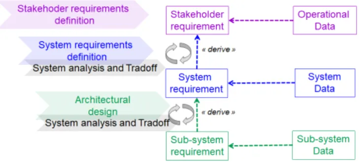
The system level of the PST approach is based on the ISO/IEC 15288 standard [11] defining systems engineering processes and terminology considering requirements and constraints issuing from the full life cycle of systems. PST builds on a subset of the standard’s processes as depicted in Fig. 1. It starts with the Stakeholder requirements definition process and therefore the definition of the related operational data. This process aims at eliciting and recording the stakeholder view on what the system should provide to achieve its goals and missions. Then the System requirements definition process focuses on the external technical specification of the system seen from a “black box” point of view. System requirements and data are derived from stakeholder requirements and used as references to guide architectural design via system analysis and tradeoffs. The Architectural design process focuses on architecture choices and considers different possible alternatives to meet the system requirements. System requirements are then decomposed following the system decomposition into sub-systems resulting from the selected architecture choices according to system analysis and tradeoffs.
Regarding system-level analyses, the PST approach has two purposes. The first one is to demonstrate whether an
2 http://www.ertms.net/
architecture solution can meet the input quantitative requirements. The second one is to determine the sub-system quantitative requirements from the sub-system property values obtained for an architecture solution.
Fig. 1. A subset if the ISO/IEC 15288 system processes used for PST
Besides, the PST approach considers a bi-directional top-down and bottom-up analysis process. The objective of the top-down analyses is to assign values to sub-system properties compliant with the input system requirements. The objective of the bottom-up analyses is to check whether the top-level assumptions determined from the top-down process on the sub-system properties values are compliant with the input requirements.
As illustrated in Fig. 2, the PST analysis process is collaborative across different specialty domain experts and includes the following main steps:
• The system engineering team shares with the specialty domain experts the input data needed to carry out the analyses. Those data are:
• Objectives and assumptions.
• Input requirements that must be satisfied by the assessed architecture.
• System Engineering (SE) properties to analyze. • Architecture views relevant for the given objectives
and assumptions.
• The specialty domain experts then perform the analyses based on computation methods specified as verification plans. These methods involve the given SE properties and additional Knowledge properties of the specialty models.
• Finally, the results of the computations defined in the verification plans are transmitted to the top-level systems engineering team for assessment of the system architecture.
Fig. 2. Involvement of specialty domains analyses for architecture assessment
Therefore, the model-based implementation of the process involves not only system models but also specific models of the specialties concerned by the analysis (Fig. 3).
The semantics of the relationships among requirements, properties and analyses supporting this bi-directional system-level process is detailed in the next section.
2) Implementation
In the following we present our implementation of the systems engineering processes presented above. We first focus on languages and tools for requirements management and system-level modeling. Then, we address the analyses supporting architecture assessment and requirements derivation. Finally, we detail a work environment supporting continuity throughout the system level and the software and hardware levels deployed on the Eclipse Integrated Development Environment (IDE).
a) Requirements
PST makes use of state-of-the-art practices implemented in Application Life Cycle Management (ALM) tools for textual requirements management. In order to ensure interoperability with most of the requirements management tools, the PST requirements are first captured and processed using the Requirements Interchange Format (ReqIF) [13]. Quantitative requirements such as performance requirements are managed following a methodology based on the principles defined in [10] for the multi-physics domains.
b) System Model
In our approach, a system model provides different views of the system organized in control units where each unit brings together a set of data handled by one of the ISO/IEC 15288 processes previously introduced.
• The first unit, including at least one view per phase of the system lifecycle, focuses on the operational data related to the Stakeholder Requirements Definition. • The second one, also including at least one view per
phase of the system lifecycle, focuses on the external specification data related to the System Requirements Definition.
• The third unit focuses on the architectural design. The model provides at least one functional/logical view relevant to a set of different physical alternative solutions candidate to assessment. Such logical shared views are extended by views highlighting the specific characteristics of each alternative solution.
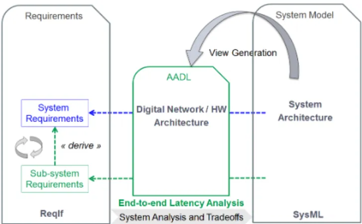
c) Connection with Specialty Models
System models also serve as headers to extract views shared with the specialty domains for specific communication needs. For example, in the case of real-time computing analysis backed by AADL models, such specific views are extracted from the SysML models as illustrated in Fig. 3. From the top level SysML model, an initial AADL model is generated where the SysML blocks representing the system in its environment are respectively represented as AADL system and abstract components.
d) Traceability
The PST approach supports cross-traceability between these model elements using a dedicated correspond relationship kind. The purpose of such links is to navigate between the different model elements and detect
inconsistencies following changes of one of the traced models.
Fig. 3. Real-time view created during architecture assessment
3) Modeling Languages and Tools
Our approach reuses a set of existing modeling languages and tools that were selected as a best fit for the covered levels of abstraction and domains. Many of these languages and tools are deployed in the Eclipse Integrated Development Environment (IDE) and use the Eclipse Modeling Framework for implementing the modeling languages. This naturally led to select Eclipse IDE as deployment platform for the PST toolchain.
a) Requirements and Modeling
Requirements are recorded using the ReqIF format and managed with the Requirements Management Framework (RMF) [14]. Besides providing a metamodel for ReqIF, RMF uses of the ProR tool to provide editors for ReqIF models.
Regarding modeling of the system level, PST leverages the Systems Modeling Language (SysML) [12] by proposing a way of use that does not depend on any specific extension based on UML stereotypes or profiles. SysML models are specified and managed with the Papyrus tool [15], which is the main UML/SysML tool of the Eclipse foundation. The real-time embedded systems specialty domain that we use to illustrate the PST approach is captured with the AADL language and its Open Source AADL Tool Environment OSATE [5]. OSATE is the reference implementation of the AADL language developed by the Software Engineering Institute (SEI).
b) Analyses
We leverage the Architecture-Led Incremental System Assurance (ALISA) framework specifically developed for AADL-based computations [16]. ALISA is a set of notations integrated with OSATE to specify requirements, verification methods, verification plans and assurance cases for systems modeled with AADL. Verification plans can be executed incrementally against AADL design models throughout the system’s development cycle in order to produce assurance cases, which are required for safety-critical systems certification. The results of executing ALISA verification plans produce evidences on whether the requirements are verified or not.
The objects shared between the systems engineering team and the real-time experts are modeled using ALISA and AADL. They consist of:
• ALISA ReqSpec requirements, which directly correspond to the ReqIF requirements. ReqSpec requirements include predicates expressed in the Resolute language [21] and define constraints involving the quantified properties of the AADL models.
• AADL property sets, which define property types and constants for the quantified properties that are expected to be determined by the analyses.
Furthermore, we take advantage of the ALISA verification plans capability to specify computation methods involved in the verification of ReqSpec requirements.
c) Traceability
The combination of models employed to generate the required views is supported by a specific cross-cutting traceability model adapted from [10] and depicted in Fig. 4.
Trace links are represented as dashed lines in the figure relating elements of models represented as boxes. References between models are represented as solid lines with cardinalities constraints like for class diagrams.
Four different types of links are provided:
• The correspond relation indicates that the linked model element are equivalent but represented in different modeling languages.
• The derive relation specifies that a requirement is derived from another one often due to a design decision or system decomposition. This is similar to the derive relation of the requirements diagram of SysML but with the difference that it is applied to external ReqIF requirements.
• The satisfy relation, also similar to the relation of the same name in the requirements diagram of
SysML means that a design element is responsible for meeting the associated requirement(s).
• The rationale relation indicates that the results computed along the verification plans serve as rationale for the related requirement(s).
In order to support such traceability relationships between model elements of different languages in in our toolchain, we used Capra [17]. Capra is an open source traceability management tool released under the Eclipse IDE. It allows creating traces between arbitrary artifacts and provides editing and visualization capabilities of the traces including traceability matrices and graph visualizations. Navigation along the traces is partially supported by automatically opening the relevant model editors. Changes on traced model elements are automatically detected and users are notified to review the impacted model elements. Capra provides a generic traceability metamodel that can be
replaced or extended to provide trace kinds specific to the artifacts used during development and to the way they are related.
For the implemented toolchain, we had to extend the generic traceability metamodel of CAPRA in order to provide classes for the aforementioned kinds of links of Fig. 4. We also proposed improvements of the navigation capability of Capra and developed the capability to handle models edited with the Xtext framework, which is used to implement all AADL and ALISA textual notations in OSATE.
B. Software and Platform Level
For the software and platform level, we define a process borrowing from the Model-Driven Architecture (MDA) [18]. MDA focuses on forward engineering, which consists of generating code from a set of abstract models. Separation of concerns is enforced by the use of different models for different concerns of the system, such as a Computation-Independent Model (CIM), a Platform-Computation-Independent Model
(PIM), a Platform-Specific Model (PSM) and a Platform Description Model (PDM).
Those models are used along a so-called “Y” development cycle (Fig. 6) where the left-hand side branch relates to applicative software development independently of any technical consideration about the run-time platform. The right-hand side branch relates to the development of the run-time platform and middleware. The base of the “Y” relates to the integration of the applicative software on the platform.
1) Transition from System Level
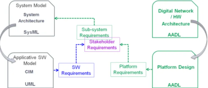
We consider two mechanisms illustrated in Fig. 5 to support transition from the system level to the software and platform level:
• Implementation of requirements traceability: The sub-system requirements become stakeholder requirements for the software and platform level.
• Implementation of shared views between upper-level and lower-upper-level models.
Fig. 5. Transition between the system and software and hardware levels
2) Left Branch of “Y” Cycle
Focusing on the left branch containing the applicative software development, the PST approach presents some slight differences from the MDA approach. On one hand, due to the real-time context, we allow the use of modeling practices and programming languages that are not object oriented. On the other hand, at this stage of our work, we did not initiate actual MDA model transformations.
However, the MDA maturity levels have proven to be suitable and we keep the MDA vocabulary.
• The CIM corresponds to a modeling level that can be shared with users and that is independent of any programming language. Our approach uses this abstraction level to make a transition between SysML system models and lower-level software models
.
We implement the transition by sharing with the software teams the functional views of the system model related to the different software components, according to Fig. 5.• The PIM relates to a software architecture view independent from any platform consideration. This level is suitable if further code generation is planned for various hardware platforms. We implement PIM models by enriching CIM models to describe high-level software architectures and record in PIM models the software UML operations or activities specifying the software functions for later development in various languages.
• The PSM refers to models for code generation. In this case, we have turned away from a strict MDA object
oriented approach to allow the use of modeling languages such as Scade or Simulink. The highest-level operators of PSM models correspond to operations or activities in PIM models.
3) Right Branch of “Y” Cycle
Regarding the right-hand side branch of the “Y” development cycle, the PDM describes the technical architecture. It focuses on the execution platform including middleware and hardware components. These are modeled with AADL so that to enable sizing analysis of the technical components (input/output processing rate of the middleware, computation speed of the processors, ….). In this case, the analysis process is the same as the system analysis process previously detailed.
4) Integration
The base of the “Y” development cycle is where virtual integration is performed. In order to support this activity, we introduce another PSM level as the actual projection level joining the two branches of the “Y”. In this case, our method deals with integrating properties such as worst case execution time of the applicative code generated from Scade or Simulink into the PDM AADL models. In this model, the software functions are represented in a thread model required to run scheduling analysis with AADL Inspector [7] and code generation with RAMSES [6].
Fig. 6. The PST “Y” process implementation
III. DEMONSTRATION CASE AND RESULTS
A. Demonstration Case
The demonstration case presented in this section had three main objectives:
• Demonstrate the feasibility of the approach.
• Study the needs regarding tooling to be addressed by commercial tool providers.
• Explore designs of the selected TMA platform with two different middleware solutions focusing on the data processing throughput.
The case relies on the ERA (European Union Agency for Railways) baseline 3 requirements for ETCS systems [20]. These systems format the signalization information for train drivers and ensure safety of trains by triggering emergency break when needed by the context. A close attention is paid to end-to-end reaction times in the case of emergency break triggering, from external event notification to completion of the expected breaking action. ETCS architectures encompass devices for communication with the track signaling equipment and the rolling stock: an odometer, a DMI and a
vital computation platform, the European Vital Computer (EVC).
In order to demonstrate the PST approach we modeled a simplified ETCS system based on a Triple Modular Redundancy (TMA) [19] vital core platform.
1) System Level Modeling and Analysis
At the system level, the objectives of the analyses are to define execution time requirements allocated to the platform functions considering a given Ethernet network solution. The worst-case transmission time analyses on the Ethernet network were carried out with the SEFA (Switched Ethernet Flow Analysis) tool [29] integrated into OSATE and the budget allocated to the device and platform functions were determined by the End-to-end Latency Analysis of OSATE.
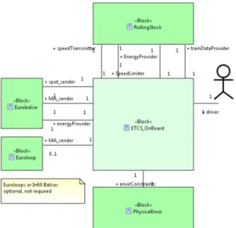
Fig. 7 depicts the modeling languages and tools used to model the ETCS on board at the system level using the PST approach. SysML is used at the system level as illustrated by Fig. 8 showing a SysML block definition diagram for the context of operation of the ETCS system. This diagram describes the relationships of the ETCS system with other systems of its environment such as the rolling stock (train) and the Eurobalise sending information such as position of the train on the rail.
Fig. 7. Overview of the tools and analyses system level for the ETCS board system
Fig. 8. A SysML block definition diagram for the context of operation of the ETCS on board system
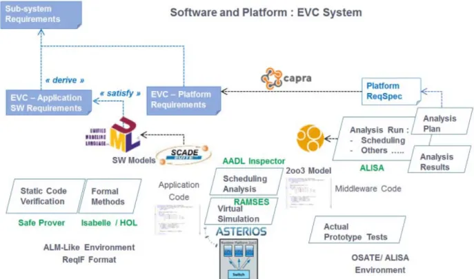
2) Software and Platform Modeling and Analysis
We also model this ETCS system on the software and platform level using AADL side for implementing a set of consistent analysis performed on an ETCS architecture based
on a Triple Modular Redundancy (TMA) [19] vital core platform.
Two different sets of AADL models are provided for first modeling the EVC, and then the overall ETCS system. In the first set of models, the EVC is represented as a system component providing details of all its internal composition including triplicated components for the 2oo3 architecture.
An abstraction of these details is also provided by defining an AADL processor component as shown in , where a dedicated Implemented_As property links the processor component to the system classifier providing the implementation details of the 2oo3 architecture.
Fig. 9. An excerpt of the EVC processor implemented as an AADL system providing the full details of the 2oo3 systems.
At the ETCS level, the provided EVC processor classifier stored in an AADL library is instantiated as a subcomponent representing the EVC in the execution platform of the ETCS.
For developing each set of these models, we use a modeling approach introduced in [29] where 5 views are provided for the concerns of:
• System context of operation: The system is represented with its interaction with entities of the environment for every system operation mode. • System functions: The system functions are
represented as abstract components without any information on whether they will be implemented as software or built-in hardware.
• Software: The software components are specified in terms of data types, subprograms and their thread execution model.
• Hardware execution platform: The hardware execution platform is specified in terms of hardware components.
• Deployment: The deployment of the software components over the aforementioned execution platform is specified using binding properties. Fig. 10 shows an AADL diagram for the context of operation (first view) of the ETCS. Similar to the SysML diagram of Fig. 8, the diagram shows the interaction of the ETCS system with entities of its environment for the normal context of operation of the ETCS system.
Dedicated traceability links are established between AADL models and their SysML counterparts following the PST approach previously described. Fig. 11 shows an example trace for the central “etcs_board” system subcomponent of viewed in the AADL textual notation (AADL has both graphical and textual notations) corresponding to the “ETCS_OnBoard” block of the SysML diagram of Fig. 8. This correspondence is captured with the “correspondsTo” trace link implemented in the Capra tool and showed in the traceability view at the bottom of Fig. 11.
Fig. 10. An AADL diagram for the context of operation of the ETCS on board system
Fig. 11. Trace link between the AADL ETCS system subcomponent and the SysML block visualized in the Capra traceability view
Regarding the analyses, from the budget determined from the system level for the application execution time, the analyses focus on the aforementioned ETCS and its EVC middleware AADL models. They aimed at evaluating the performance of different middleware solutions compared to the required input processing rate of the EVC application (number of incoming messages per second) given its
integration in the enclosing ETCS model.
Mono and multicore solutions are assessed for the EVC depending on the result of scheduling analyses using AADL Inspector and end-to-end latency analyses using OSATE.
In the end, the real 2oo3 middleware is implemented using code generated from the Krono-Safe / Asterios tool suite [29] and tests are performed on the real hardware platform. summarizes the implementation of the approach for the software and platform level for the EVC.
B. Results
At the system level, the results of the real-time analyses allowed us to validate the integration of the application within the middleware and to select the best HW execution platform, as well as figuring out its cost.
At the software and platform level, the analyses results were compared with the real EVC implemented as three Apalis iMX6 development boards connected via Ethernet with a switch.
Our demonstration case allowed assessing the following: • Usage of AADL for the railway domain:
Redundancy is often used in the railway domain to deal with safety, reliability and availability requirements. AADL proved to be well suited to model these architectures through the different views involved in our process, all the way down to precise software and hardware models ready for code-generation and deployment.
• Usage of ALISA for automated verification and
assurance case modeling:
ALISA has proven very valuable in:
• Expressing design level requirements and providing continuity up to the system level requirements. • Acceptance of design alternatives through the
verification of predicates derived from requirements
(schedulability, structural compliance with the TMR architecture, etc.).
• Comparison of design alternatives through the computation of design KPIs, such as hardware cost, processor MIPS, response time, etc.
• Relevance of a continuous integration toolchain: The ALISA environment also proved to be pluggable into a continuous integration server, allowing the verification of the platform level requirements every time changes in requirements, design or verification procedures were published by contributors. This is further detailed in [24].
Other benefits were:
• Recording development history and milestones of the project with associated KPIs values per design alternative.
• Modularity of the models decomposed into components that can be independently verified to some extent, much like software components can be unit-tested.
IV. CONCLUSION
We have proposed and evaluated the PST system development process including requirements and design models management across different levels supported by model-based real-time analyses meeting our research objectives.
While the proposed PST approach focuses on the real-time embedded systems specialty domain, it should allow for being integrated within upper-level systems engineering tradeoff processes among different disciplines like safety, mutliphysics, carbon emission, …. However, this integration would mean opening the OSATE Eclipse-based development environment to other non-Eclipse-based systems engineering workbench of the market, which is left as future work.
Other future work consists of improving traceability management that is currently implemented with the Capra tool. In this case, both models from the system and the specialty domains are created completely manually and must be manually maintained as they are concurrently modified. In the ideal world, tools would be provided that can automatically generate out of a system model a first set of domain specialty models and maintain these models consistent as any of them models are modified during concurrent engineering. As further detailed in [25], despite huge efforts on developing tools for model synchronization over the past 20 years, this remains a difficult problem especially when industrial rich languages such as SysML and AADL are involved.
Thanks to prior research in the frame of the PST project such as [21] and [22], we have found that proof assistants such as Isabelle [23] provide adequate expressivity to formalize sets of requirements and constraints, which is very promising in terms of requirements and traceability consistency and satisfiability analysis. We are planning to improve the next steps of the PST approach by integrating such capabilities to our toolchain.
REFERENCES
[1] Jorgen Hansson, Steven Helton, and Peter Feiler. ROI Analysis of the System Architecture Virtual, 2018
[2] Bruce Powell Douglass “Doing Hard Time,” Addison Wesley, 1999
[3] SAE (Society of Automotive Engineers) international, Architecture Analysis & Design Language (AADL) AS5506, 2004, https://www.sae.org/standards/content/as5506/
[4] OMG (Object Management Group), UML Profile for MARTE: Modeling and Analysis of Real-Time Embedded Systems, version 1.0, 2009, https://www.omg.org/spec/MARTE/1.0/P
[5] OSATE Website: https://osate.org
[6] RAMSES Website: https://mem4csd.telecom-paristech.fr/blog/index.php/ramses/
[7] AADL Inspector Website: https://www.ellidiss.com/products/aadl-inspector/
[8] Pierre de Saqui-Sannes, Jérôme Hugues. Combining SysML and AADL for the Design, Validation andImplementation of Critical Systems. ERTS2 2012, Feb 2012, Toulouse, France. pp.117.
[9] Zhe, Wang and Hugues, Jérôme and Chaudemar, Jean-Charles and LeSergent, Thierry An Integrated Approach to Model Based Engineering with SysML, AADL and FACE. (2018) In: Aerospace Systems and Technology Conference, 6November 2018 - 8 November 2018 (London, United Kingdom).
[10] Françoise Caron, Leveraging tradeoff, bridging the gap among disciplines, 26th Annual INCOSE International Symposium (IS 2016) Edinburgh, Scotland, UK, July 18-21
[11] ISO, IEC and IEEE (International Organisation for Standardisation, International Electrotechnical Commission and Institute of Electrical and Electronics Engineers). 2015. ISO/IEC/IEEE 15288: 2015. “Systems and Software Engineering — System Life Cycle Processes”.
[12] OMG (Object Management Group) 2012. OMG Systems Modeling Language (OMG SysML™), Version 1.3,
http://www.omg.org/spec/SysML/1.3/.
[13] OMG (Object Management Group) 2016, Requirements Interchange Format, Version 1.2, https://www.omg.org/spec/ReqIF/About-ReqIF/ [14] RMF Website: https://www.eclipse.org/rmf/
[15] Papyrus Website: https://www.eclipse.org/papyrus/
[16] Julien Delange, Peter Feiler and Neil Ernst. Incremental Life Cycle Asurance of Safety-critical Systems. 8th European Congress on Embedded Real Time Software and Systems (ERTS), 2016.
[17] Capra Website: https://projects.eclipse.org/projects/modeling.capra [18] OMG MDA Website: https://www.omg.org/mda/
[19] Robert E Lyons and Wouter Vanderkulk. The use of Triple-Modular Redundancy to Improve Computer Reliability. IBM journal of research and development, 6(2):200–209, 1962.
[20] ERA Website: http://www.era.europa.eu/Core-Activities/ERTMS/Pages/Set-of-specifications-3.aspx
[21] Achim D. Brucker, Idir Ait-Sadoune, Paolo Crisafulli, and Burkhart Wolff. Using the isabelle ontology framework: Linking the formal with the informal. In Conference on Intelligent Computer Mathematics (CICM), number 11006 in Lecture Notes in Computer Science. Springer-Verlag, Heidelberg, 2018.
[22] Sergio Bezzecchi, Paolo Crisafulli, Charlotte Pichot and Burkhart Wolff. Making agile development processes fit for v-style certification procedures. In ERTS'18, ERTS Conference Proceedings, 2018.
[23] Isabelle Website: https://www.cl.cam.ac.uk/research/hvg/Isabelle/ [24] Paolo Crisafulli, Dominique Blouin, Françoise Caron and Cristian
Maxim. Engineering Railway Systems with anArchitecture-Centric Process Supported by AADL and ALISA: an Experience Report. In ERTS'20, ERTS Conference Proceedings, 2020.
[25] Dominique Blouin, Alain Plantec, Pierre Dissaux, Frank Singhoff and Jean-Philippe Diguet. Synchronization of Models of Rich Languages with Triple Graph Grammars: an Experience Report. In International Conference on Theory and Practice of Model Transformations, 2014. [26] Andrew Gacek, John Backes, Darren Cofer, Konrad Slind, and Mike
Whalen. Resolute: an AssuranceCase Language for Architecture Models. In ACM SIGAda Ada Letters, volume 34, pages 19–28. ACM, 2014.
[27] SEFA Website: https://mem4csd.telecom-paristech.fr/blog/index.php/switched-ethernet-flows-analysis/ [28] Dominique Blouin and Etienne Borde. AADL: A Language to Specify
the Architecture of Cyber-Physical Systems. In Foundations of Multi-Paradigm Modeling for Cyber-Physical Systems, Springer, 2020. [29] Krono-Safe Website: https://www.krono-safe.com/