Li`
ege Universit´
e
Facult´
e des Sciences appliqu´
ees
Department of Chemical Engineering
Development of new catalysts for
proton exchange membrane fuel
cells (PEMFCs)
Anthony Zubiaur
Supervisor:
Nathalie Job
A thesis submitted in fulfillment of the requirements
for the degree of Doctor of Philosophy in Engineering
Acknowledgements
I want to thank Prof. Nathalie Job, the supervisor of this thesis, for proposing this thesis subject to me, and also for her availability, her meticulous proofreading and her patience.
I also want to thank Dr. Sandrine Berthon-Fabry from MINES ParisTech, Prof. Sophie Hermans from Universit´e Catholique de Louvain, Dr. Isotta Cerri from Toyota Motor Europe, as well as Dr. St´ephanie Lambert and Prof. Ang´elique L´eonard from Li`ege Universit´e for accepting to be part of the thesis jury.
I would like to thank the people from the Laboratoire d’Electrochimie et de Physicochimie des Mat´eriaux et des Interfaces (LEPMI) of Universit´e de Grenoble for their welcome. In particular, I want to thank Prof. Marian Chatenet and Dr. Fr´ed´eric Maillard for teaching me the basis of electrochemical measurements with a three electrode cell and for discussions about the obtained results, not forgetting Dr. Laetitia Dubau for TEM, STEM, and EDX measurements and discussions.
I want to thank people who helped me with physicochemical measurements: Mar-tine Dejeneffe from Li`ege Universit´e for TEM measurements and discussions, Prof. B´en´edicte Vertruyen from Li`ege Universit´e for XRD measurements and discussions, Anne Iserentant from Universit´e Catholique de Louvain for ICP-AES measurements, and Dr. Yan Busby from Universit´e de Namur for XPS measurements.
I would also like to thank Alice Dubus from Li`ege Universit´e, our glass blower, who did an excellent work with the three electrode cell setup and was always available when glass broke.
Obviously, I would like to thank all the people from the Department of Chemi-cal Engineering of Li`ege Universit´e and, particularly, the people from the so-called ’carbon group’ for the good work atmosphere and discussions (not especially about work). I will not cite everyone but you will stay in my memory.
I would like to thank Dr. Ir. Pierre-Yves Olu for fruitful discussions.
Finally, I thank my friends and family, which are always there for me when needed. Special thanks to Cl´ementine for her daily help and support.
Abstract
In this thesis, the synthesis and the physicochemical and electrochemical char-acterization of carbon xerogel-supported electrocatalysts for proton exchange mem-brane fuel cells (PEMFCs) were studied. It is structured around three axes: (i) the synthesis and characterization of catalysts constituted of Pt nanoparticles deposited on carbon xerogel (Pt/CX catalysts) with high Pt loading and the streamlining of the synthesis process in order to speed up the synthesis method and avoid Pt losses; (ii) the synthesis and characterization of (solid and hollow) PtCo nanoparticles de-posited on carbon xerogel (PtCo/CX catalysts); and (iii) the durability study of the best catalysts synthesized in the two previous parts, in a three electrode cell (liquid electrolyte) and in a PEMFC, through accelerated stress tests (ASTs).
First, the strong electrostatic adsorption (SEA) method was adapted in order to synthesize Pt/CX catalysts with Pt loading up to 25 wt.% with as low Pt losses as possible. The resulting Pt/CX catalysts, obtained by multiple impregnation-drying-reduction cycles, display small Pt nanoparticles (ca. 2-3 nm) with a narrow particle size distribution. The electrochemical properties of these Pt/CX catalyst, i.e. the electroactive Pt surface area and the specific and mass activity for the oxygen reduction reaction (ORR), are constant, whatever the Pt loading. To avoid any Pt losses during the synthesis of Pt/CX catalysts and to speed up the synthesis process, a streamlining of the method was performed. Multiple-step methods, e.g. charge enhanced dry impregnation (CEDI) and reduction of Pt ions by sodium borohydride, and one-step methods, e.g. reduction of Pt ions by formic acid and Pt colloid synthesis, were studied. From this investigation, the best Pt/CX catalysts for the ORR are those synthesized by SEA, CEDI, and formic acid reduction methods. They exhibit higher activity for the ORR than a commercial Pt/HSAC catalyst. Only the last synthesis method is a one-step method. It allows depositing in a single step up to at least 37 wt.% of Pt particles with average diameter around 3-4 nm.
Then, methods to synthesize PtCo/CX catalysts were developed. Indeed, the alloying of Pt with transition metal, Co in this case, allows increasing the catalytic activity for the ORR. The first method is based on the SEA method. It consists in successive or simultaneous deposition of Pt and Co. However, only the successive
ABSTRACT
deposition of Pt followed by that of Co yields bimetallic catalyst. Even so, the two metals deposited on the CX were not alloyed. As a result, no activity enhancement was observed. The other method is based on the colloid method. It yields hollow PtCo nanoparticles, with an average particle size of ca. 50 nm, deposited on CX. These hollow PtCo/CX catalysts exhibit very high activity (specific activity between 14 and 20 times as high and mass activity around 7 times as high as that of a commercial Pt/HSAC reference catalyst).
Finally, the durability of the best synthesized catalysts (formic acid-reduced Pt/CX and hollow PtCo/CX catalysts) was studied in a three electrode cell (liquid electrolyte) and in PEMFC, using ASTs which consist in cycling the potential of the working electrode (i.e. the catalytic layer) between 0.6 and 1.0 V vs. RHE. The major result of the durability study is that, contrary to Pt/CX and Pt/HSAC catalysts, the hollow PtCo/CX catalysts exhibit very good morphology stability during the ASTs. Moreover, in PEMFC, the activity of hollow PtCo/CX catalysts stabilizes quickly and no degradation of performance could be seen between 10,000 and 30,000 AST cycles, contrary to pure Pt catalysts which exhibit a continuous decrease in performance.
R´
esum´
e
Cette th`ese consiste en l’´etude de la synth`ese d’´electrocatalyseurs support´es sur x´erogel de carbone pour piles `a combustible `a membrane ´echangeuse de protons (PEMFCs) ainsi que leur caract´erisation physicochimique et ´electrochimique. Elle comporte trois parties: (i) la synth`ese et la caract´erisation de catalyseurs constitu´es de nanoparticules de Pt d´epos´ees sur un x´erogel de carbone (Pt/CX); (ii) la synth`ese et la caract´erisation de catalyseurs constitu´es de nanoparticules (pleines ou creuses) de PtCo d´epos´ees sur un x´erogel de carbone (PtCo/CX); (iii) l’´etude de la durabilit´e des catalyseurs les plus performants synth´etis´es lors des deux premi`eres parties, durant des essais de d´egradation acc´el´er´ee ( ou “accelerated stress tests”, ASTs), en cellule `a trois ´electrodes (´electrolyte liquide) ainsi qu’en PEMFC.
D’abord, la m´ethode dite de “strong electrostatic adsorption” (SEA) a ´et´e adapt´ee afin de synth´etiser des catalyseurs Pt/CX pr´esentant des teneurs en Pt jusqu’`a 25 %mass. tout en limitant les pertes de Pt autant que possible. Les catalyseurs
Pt/CX obtenus sont compos´es de petites particules de Pt d’environ 2-3 nm avec une distribution de taille ´etroite. Les propri´et´es ´electrochimiques de ces cataly-seurs Pt/CX, c’est-`a-dire la surface sp´ecifique de Pt ainsi que l’activit´e sp´ecifique et massique pour la r´eduction de l’oxyg`ene (ORR), sont constantes quelle que soit la teneur en Pt. Afin d’´eviter toute perte de Pt durant la synth`ese et d’acc´el´erer cette derni`ere, une rationalisation du proc´ed´e a ´et´e effectu´ee. Des m´ethodes de d´epˆot de Pt en plusieurs ´etapes, comme la technique dite de “charge enhanced dry impregnation” (CEDI) ou un proc´ed´e utilisant le borohydrure de sodium comme r´educteur des ions Pt, ainsi que des techniques de d´epˆot de Pt en une seule ´etape, comme la m´ethode utilisant l’acide formique comme r´educteur des ions Pt ou le proc´ed´e collo¨ıdal, ont ´et´e ´etudi´ees. Les meilleures performances pour l’ORR ont ´et´e obtenues par synth`ese SEA, CEDI ou via r´eduction du pr´ecurseur de Pt par l’acide formique. Seule cette derni`ere m´ethode est r´ealis´ee en une seule ´etape. Elle permet de d´eposer, en une seule op´eration, jusqu’`a au moins 37 %mass. de particules de Pt
de 3-4 nm de diam`etre.
Ensuite, des synth`eses de catalyseurs PtCo/CX ont ´et´e d´evelopp´ees. En effet, la pr´esence d’alliage Pt-m´etal de transition, dans ce cas-ci du Co, permet d’augmenter l’activit´e pour l’ORR des catalyseurs. La premi`ere se base sur la m´ethode SEA.
R´ESUM´E
Elle consiste en une d´eposition successive ou simultan´ee de Pt et de Co. Cependant, seul le d´epˆot successif de Pt suivi de celui de Co a permis d’obtenir des catalyseurs bim´etalliques. Malgr´e la pr´esence des deux m´etaux sur le support, aucun alliage n’a pu ˆetre form´e, et les performances des catalyseurs n’ont donc pas ´et´e am´elior´ees. La seconde et derni`ere m´ethode ´etudi´ee est bas´ee sur la formation d’un collo¨ıde m´etallique (similaire au collo¨ıde de Pt pr´ec´edemment ´evoqu´e). Cette m´ethode a permis d’obtenir des catalyseurs constitu´es de particules creuses de PtCo d’environ 50 nm de diam`etre support´ees sur x´erogel de carbone. L’activit´e de ces catalyseurs PtCo/CX `a particules creuses est la plus ´elev´ee de cette th`ese (une activit´e sp´ecifique 14 `a 20 fois plus ´elev´ee que celle du catalyseur commercial Pt/HSAC de r´ef´erence ainsi qu’une activit´e massique environ 7 fois plus ´elev´ee).
Finalement, la durabilit´e des catalyseurs les plus performants synth´etis´es pr´ec´ e-demment (le catalyseur Pt/CX r´eduit par l’acide formique ainsi que le catalyseur PtCo/CX `a particules creuses) `a ´et´e ´etudi´ee en cellule `a trois ´electrodes (´electrolyte liquide) ainsi qu’en PEMFC, sur base d’ASTs. Ces ASTs consistent `a faire cycler le potentiel de l’´electrode de travail (autrement dit, le potentiel de la couche cataly-tique) entre 0,6 et 1,0 V vs. RHE. Le r´esultat le plus marquant de cette ´etude de durabilit´e est que, contrairement aux catalyseurs Pt/CX et Pt/HSAC, les cataly-seurs PtCo/CX `a particules creuses montrent une tr`es bonne stabilit´e morphologique durant les ASTs. De plus, en PEMFC, l’activit´e de ces catalyseurs se stabilise rapide-ment et aucune d´egradation de l’activit´e n’a pu ˆetre observ´ee entre 10.000 et 30.000 cycles, contrairement aux catalyseurs de Pt pur, dont les performances continuent de d´ecroˆıtre avec le nombre de cycles.
Contents
Acknowledgements i Abstract iii R´esum´e v Introduction 1 References . . . 171 Using the multiple SEA method to synthesize Pt/carbon xerogel electrocatalysts for PEMFC applications 23 1.1 Introduction . . . 24 1.2 Experimental . . . 25 1.2.1 Synthesis . . . 25 1.2.2 Physicochemical Characterization . . . 26 1.2.3 Electrochemical Characterization . . . 27 1.3 Results . . . 29 1.3.1 Physicochemical Characterization . . . 29 1.3.2 Electrochemical Characterization . . . 32 1.4 Discussion . . . 34 1.5 Conclusion . . . 36 References . . . 37
2 Streamlining of the synthesis process of Pt/carbon xerogel electro-catalysts with high Pt loading for proton exchange membrane fuel cells (PEMFCs) 39 2.1 Introduction . . . 40 2.2 Experimental . . . 42 2.2.1 Reagents . . . 42 2.2.2 Syntheses . . . 42 2.2.3 Physicochemical characterization . . . 45 2.2.4 Electrochemical characterization . . . 48 2.3 Results . . . 50
CONTENTS
2.4 Discussion . . . 63
2.5 Conclusion . . . 68
References . . . 70
3 Impregnation methods to synthesize PtCo/carbon xerogel electro-catalysts for the oxygen reduction reaction 73 3.1 Introduction . . . 74 3.2 Experimental . . . 75 3.2.1 Reagents . . . 75 3.2.2 Syntheses . . . 75 3.2.3 Physicochemical characterization . . . 77 3.2.4 Electrochemical characterization . . . 78 3.3 Results . . . 80 3.3.1 Physicochemical characterization . . . 80 3.3.2 Electrochemical characterization . . . 85 3.4 Discussion . . . 89 3.5 Conclusion . . . 94 References . . . 96
4 Synthesis and characterization of hollow PtCo nanoparticles sup-ported on carbon xerogel as electrocatalysts for the oxygen reduc-tion reacreduc-tion 99 4.1 Introduction . . . 100 4.2 Experimental . . . 101 4.2.1 Syntheses . . . 101 4.2.2 Physicochemical characterization . . . 103 4.2.3 Electrochemical characterization . . . 104 4.3 Results . . . 106 4.3.1 Physicochemical characterization . . . 106 4.3.2 Electrochemical characterization . . . 110 4.4 Discussion . . . 112 4.5 Conclusion . . . 120 References . . . 122 Appendix . . . 127 4.A1 Reproducibility . . . 127
5 Durability of Pt and hollow PtCo nanoparticles supported on car-bon xerogel designed as electrocatalysts for the oxygen reduction reaction 131 5.1 Introduction . . . 132 5.2 Experimental . . . 134 5.2.1 Syntheses . . . 134 5.2.2 Physicochemical characterization . . . 135 5.2.3 Electrochemical characterization . . . 135
CONTENTS
5.3 Results . . . 138
5.3.1 Physicochemical characterization . . . 138
5.3.2 Electrochemical characterization . . . 141
5.3.3 Accelerated stress tests at 353 K . . . 144
5.4 Discussion . . . 147
5.4.1 Accelerated stress tests at 353 K . . . 150
5.5 Conclusion . . . 152
References . . . 154
Appendix . . . 159
5.A1 Effect of the electrolyte . . . 159
5.A2 Effect of hollow particle size on ASTs . . . 161
6 Durability of Pt and hollow PtCo nanoparticles supported on car-bon xerogel during accelerated stress tests performed in proton exchange membrane fuel cell (PEMFC) 163 6.1 Introduction . . . 164
6.2 Experimental . . . 166
6.2.1 Syntheses . . . 166
6.2.2 Physicochemical characterization . . . 167
6.2.3 Fuel cell characterization . . . 168
6.2.4 Measurement procedure and accelerated stress tests . . . 171
6.3 Results . . . 172
6.3.1 Physicochemical characterization . . . 172
6.3.2 Fuel cell characterization . . . 175
6.3.3 Accelerated stress tests . . . 178
6.4 Discussion . . . 182
6.4.1 Accelerated stress tests . . . 184
6.5 Conclusion . . . 186
References . . . 188
Appendix . . . 191
6.A1 PEIS and crossover results . . . 191
Conclusion and outlook 193 Conclusion . . . 193
Outlook . . . 196
References . . . 198
Appendix 199 A1 Introduction to electrochemical measurements in three-electrode cell . 199 A1.1 Cyclic voltammetry . . . 201
A1.2 CO stripping voltammetry . . . 201
A1.3 Measurement of the activity for the ORR . . . 203
A2 Introduction to electrochemical measurements in proton exchange membrane fuel cell . . . 204
CONTENTS
A2.2 Potential electrochemical impedance spectroscopy - PEIS . . . 205 A2.3 Crossover measurement . . . 206 A2.4 Amperometry . . . 207 References . . . 209
Introduction
Context
World population grows every day. In developed and developing countries, this growth causes a dramatic increase in the world energy consumption. To fulfill the worldwide energy demand, our current power supply system must change. Indeed, the fossil fuels, i.e. oil, gas, and coal, which provide ca. 85% of the world energy, are available in limited quantity. Moreover, their combustion impacts the environment, by emitting greenhouse gases, which take part in climate change, as well as particles and unburned fuel, which cause pollution.
A possible solution to decrease the impact of energy consumption is to diversify and increase the efficiency of the power generation systems. Particular attention should be paid to renewable energies. Biomass, hydro, thermal, wind, and solar electricity are among the most promising sustainable energies [1]. However, the technologies producing these sustainable energies are not mature enough or are too expensive to fully replace the use of fossil fuels in the short term. One major drawback for the wide-spreading of sustainable energy is the intermittence of some of these power sources.
To overcome this problem, the development of storage systems is necessary to store the excess of power produced during peak hours in order to deliver energy when needed. Particularly interesting storage devices are electrochemical systems, such as batteries or electrolyzers and fuel cells. The last two are electrochemical storage devices (electrolyzers) coupled with electrochemical conversion systems (fuel cells). The coupling operates as follows: electrolyzers transform electrical energy into chemical energy, i.e. via water electrolysis, while fuel cells convert back the chemical energy into electrical energy [2]. This coupling exhibits a remarkable advantage: the fuel (usually H2) containing the energy can be stored for a very long time. Indeed, electrolyzers can produce H2 from renewable electricity, e.g. hydro, solar, or wind electricity. Produced H2 can then be stored in tanks and transported towards the energy consumer, where fuel cells convert back the chemical energy of H2 into electricity. The transport between the source and the consumer can also be carried
INTRODUCTION
Figure 1: Schematic representation of an acidic medium fuel cell.
out by H2 pipelines or networks of pipes. As electrolyzers and fuel cells are based on the same principles, one operates as the reverse of the other. For this process to function with as little loss as possible, the two devices must display high efficiencies.
Fuel cells
Focusing on the energy conversion system, i.e. the fuel cell, Figure 1 illustrates the production of electricity from H2molecules in an acidic medium. The description of the fuel cell functioning will be explained on the basis of H2-fueled acidic medium cells, as this thesis is focused on this very common fuel cell type. For the other kinds of fuel cells, the base principles are the same but some parameters change, e.g. the utilized fuel (CH4, alcohol, etc.) or the electrolytic medium. For instance, in the case of alkaline fuel cells, the half reactions are different, the charge carrier is OH−, and the water is produced at the anode.
As any electrochemical cell, a fuel cell is constituted of (i) an anode, where oxida-tion takes place, (ii) a cathode, where the reducoxida-tion occurs, and (iii) an electrolyte, which electrically insulates the anode from the cathode but allows the ions to cross from one side to the other. In the case of an acidic fuel cell, H2 molecules enter the (porous) anode, where they are reduced into protons, yielding electrons according to the hydrogen oxidation reaction (HOR):
H2 −→ 2H++ 2e−
INTRODUCTION
The produced electrons leave the anode through the external circuit, to power an electrical device. The protons leave the anode, cross the electrolyte, and react at the cathode with electrons and oxygen molecules, producing water according to the oxygen reduction reaction (ORR):
O2 + 4H++ 4e− −→ 2H2O (2) In addition to water and electricity, fuel cells also produce heat during operation as the system is, of course, not thermodynamically ideal.
Many kinds of fuel cells are currently developed and some of them are already commercialized. Table 1 (adapted from Reference [3]) shows the main characteristics of different types of fuel cells. This list is non-exhaustive, since other types of fuel cells can be emerging but are still under research nowadays. Briefly, these fuel cells can be distinguished from each other on the basis of the electrolyte (solid or liquid), of their working temperature, and of the fuel used. Solid oxide fuel cells use O2−-conductive electrolyte at temperature above 1000 K. Molten carbonate fuel cells include liquid CO2−3 -conductive electrolyte (i.e. molten carbonate salts) at 873-973 K. Phosphoric acid fuel cells are based on liquid H+-conductive electrolyte
at 433-493 K. These three kind of fuel cells, which work at high temperature, are already commercialized for stationary applications, such as micro-combined heat and power, emergency power systems, or uninterruptible power supplies. Alkaline fuel cells, where the electrolyte is an alkaline solution (usually KOH in water), i.e. the mobile species is OH−, exhibit a wide range of temperature and pressure operating conditions, leading to a wide application range, from the above-mentioned stationary applications to mobile and portable devices. For example, they were already used during the Apollo space program in the 1960s. However, their sensitivity to CO and CO2 prevents their utilization in town (due to CO and CO2 from the air) and their fueling from H2 produced by steam methane reforming (as it also produces CO and CO2). Direct borohydride fuel cells are an emerging kind of mobile and portable alkaline fuel cells, fueled with sodium borohydride (NaBH4). Enzymatic fuel cells decompose organic matter (glucose) to produce electricity. These fuel cells are mainly used as power sources for implantable medical micro-sensors and devices. Proton exchange membrane fuel cells (PEMFCs) are fueled by H2 and use a polymer membrane as electrolyte. They are one of the most studied fuel cells types because of (i) their temperature and pressure operating ranges, which are closer to the ambient, and because of (ii) their higher power density and their better dynamic characteristics than other types of fuel cells [4]. Their functioning is described with more details in the next section. Other types of fuel cells derive from PEMFCs: (i) direct alcohol fuel cells, which use methanol, ethanol, and other alcohols as a fuel; (ii) direct formic acid fuel cells, which are fueled with formic acid; and (iii) high-temperature proton exchange membrane fuel cells, which work at higher temperature than the classic PEMFCs. Researchers are still developing PEMFCs but they are already commercialized from above-mentioned stationary applications to mobile applications, e.g. cars or buses.
INTR
ODUCTION
Table 1: Fuel cell types and main characteristics (adapted from Reference [3]).
Fuel cell type Fuel Charge carrier
Operation temperature
K
Application Commercialized
Solid oxide CH4 O2− 1073-1273 Stationary Yes
Molten carbonate CH4 CO2−3 873-973 Stationary Yes
Alkaline H2 OH− Below 273-503
Stationary Miniaturized
Mobile
Yes
Phosphoric acid H2 H+ 433-493 Stationary Yes
High-temperature proton exchange membrane
H2 H+ 383-453 StationaryMobile Yes
Direct alcohol Methanol, ethanol H+ Ambient-393 MiniaturizedMobile Yes Direct borohydride Sodium borohydride (NaBH4) Na + / OH− 293-358 Miniaturized Mobile No Low-temperature proton exchange membrane
H2 H+ 333-353 StationaryMobile Yes
Direct formic acid Formic acid
(HCOOH) H
+ 303-333 Miniaturized
Mobile No
Enzymatic Organic matter
(glucose) H
+ 293-333 Miniaturized No
INTRODUCTION
Proton exchange membrane fuel cells (PEMFCs)
The proton exchange membrane fuel cell (PEMFC) is a versatile device with a lot of possible uses. PEMFCs components and their roles are described hereafter. Figure 2 is a picture of classic components of a PEMFC.
The core of a PEMFC device is the membrane electrode assembly (MEA). The MEA is composed of a polymer membrane covered by catalytic layers on both sides. The polymer membrane, usually made of perfluorosulfonic acid (PFSA), named Nafion®when distributed by Du Pont de Nemours, is an electric insulator but a pro-ton conductor when properly hydrated. It is sandwiched between the two catalytic layers, which constitute the electrodes (anode and cathode). PFSA is composed of long polytetrafluoroethylene (PTFE) backbones, grafted with perfluorovinyl ether groups terminated by a sulfonate function which is the acidic site allowing proton conduction. Figure 3 shows the chemical structure of a PFSA membrane.
To speed up the oxidation and reduction reactions, catalytic layers are present on both sides of the polymer electrolyte membrane (PEM) and constitute the electrodes of the cell; the HOR occurs at the anode, whereas the ORR occurs at the cathode. Both electrodes are often manufactured from the same components: (i) catalytic sites, usually platinum or platinum-based nanoparticles, which catalyze both reac-tions (HOR and ORR); (ii) a porous support for these catalytic sites, usually high surface area carbon (HSAC), which maintains the dispersion of the catalytic sites,
INTRODUCTION
Figure 3: Chemical structure of a perfluorosulfonic acid (PFSA) membrane [5].
conducts electrons from or towards the active sites, and exhibits porosity so that the gaseous reactive species and the product (H2, O2, and water) can diffuse towards or from the active sites; and (iii) an ionomer, usually Nafion®, which conducts protons between the active sites and the PEM.
The assembly of the fuel cell components is schematized in Figure 4a for a mono-cell configuration. As for Figure 4b, it schematizes the cathode catalytic layer, while Figure 4c zooms in on a platinum nanoparticle deposited on the carbon support. In order that the ORR reaction occurs, as shown by Equation (2), all the reactants must be in contact with the active sites. In other words, (i) O2 molecules, usu-ally from air, must be able to access platinum nanoparticles by diffusion through the porosity of the catalytic layer and through the ionomer; (ii) protons must ac-cess platinum nanoparticles by transport through the ionomer network within the electrode; (iii) electrons must access platinum nanoparticles through the conductive carbon support; and (iv) produced water molecules must be able to leave the plat-inum particles by diffusion through the ionomer and through the porosity of the catalytic layer. Besides these contact issues, the reaction pathway of the ORR is very complex and involves a lot of adsorbed intermediate species. Stamenkovic et al. proposed the following schematic pathway [6]
O2 O2,ad k1 H2O2,ad k2 H2O
k3
k−3
H2O2
(3)
where the rate-determining step is the first charge transfer happening after the adsorption of O2 on the platinum surface:
O2,ad+ e− −→ O−2,ad (4)
Gas diffusion layers (GDLs), usually constituted of carbon cloth impregnated by poly-vinylidene fluoride (PVDF) and covered by a layer of microporous carbon, are
INTRODUCTION
Figure 4: Schematic representation of a PEMFC (a), of the cathode catalytic layer (b), and enlargement of a platinum nanoparticle (c).
INTRODUCTION
placed on both sides of the MEA. The roles of the GDLs are (i) to spread the reactive gases all over the catalytic layers, (ii) to help to evacuate the excess water produced by the cell, and (iii) to conduct electrons between the catalytic layer and the next component, the bipolar plates. Bipolar plates, usually constituted of graphite, metal (stainless steel, titanium, etc.), or composites, display engraved channels, which distribute the reactive gases over the GDLs. Moreover, these electrically conductive plates allow the electrons to cross from the GDLs to the current collectors, the latter being connected to the external electrical device to be powered. Finally, gaskets are placed around GDLs, between the MEA and the bipolar plates, in order to prevent gas leaks, especially H2. All the components are held together and pressed by two flanges and screws.
The voltage of one single PEMFC is limited by thermodynamics. The maximum cell voltage, given by the Nernst equation, is equal to 1.23 V at 298 K and under standard conditions. At usual operating conditions (temperature around 343-353 K and pressure around 1-2 bar), the equilibrium cell voltage decreases to 1.17 V. This voltage can never be reached during operation, as it corresponds to the ideal voltage, i.e. to the voltage performed when no current is produced. In fact, when a cell produces electricity, the system is not ideal anymore, leading to a loss of electrical work in the form of heat. This conversion of chemical energy into heat instead of electricity results in voltage losses, also called overpotentials. These overpotentials cause the ca. 1 V of maximal tension that one single fuel cell can usually display. In order to increase the total voltage, fuel cells are piled up, forming the so-called fuel cell stacks (Figure 5). The voltage of a fuel cell stack is then the sum of the voltage of all the piled-up cells. The geometrical surface area of the cells can also be increased to produce higher current.
Drawbacks of PEMFCs
PEMFCs still exhibit several limitations hampering their extensive worldwide commercialization, e.g. the manufacturing of the components, the assembly of the elements, the heat and water management, the production, distribution, and storage of H2, etc. Besides these limitations, the cell components can also be improved. For example, the catalytic layers display properties which are still not optimal, such as (i) their relatively low activity, (ii) their low stability (especially at the cathode), and (iii) their non-optimal architecture. Commonly used catalysts are platinum nanopar-ticles deposited on high surface area carbon (Pt/HSAC). Platinum nanoparnanopar-ticles are used in order to speed up the sluggish ORR. However, platinum does not exhibit the optimal activity for this specific reaction. Indeed, in order to display good activity for chemical reactions which involve adsorbates, e.g. ORR which involves the ad-sorption of O2 molecules and oxygenated intermediates, catalytic sites must exhibit an optimal binding energy with the reactive species. In other words, the binding energy between active sites and adsorbates must be neither too weak (otherwise the adsorbates cannot adsorb on the active sites and the reaction does not occurs) nor
INTRODUCTION
Figure 5: Scheme of a fuel cell stack (adapted from Reference [7]).
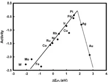
too strong (otherwise the adsorbed species stay on the active sites and do not disso-ciate, leading to a poisoning of the active sites), following the well-known Sabatier’s principle. When considering the binding of O2 molecules and oxygenated interme-diates, among all the pure metals, platinum exhibits the best activity for ORR, as shown by Figure 6 illustrating Sabatier’s principle in this case [8]. However, the binding energy between platinum atoms and the oxygenated intermediates of the ORR is ca. 0.2-0.3 eV too high [8, 9], which leads to kinetic limitations.
Another limitation is the instability of Pt/HSAC catalysts under PEMFC condi-tions [10–13]. When focusing on the degradation of platinum nanoparticles, several phenomena can occur. First, platinum atoms from small particles can dissolve, dif-fuse, and redeposit on large ones. This phenomenon is called the electrochemical Ostwald ripening. This process is driven by the diminution of the surface energy of the particles when transferred from small to large ones. Second, platinum crys-tallites can migrate at the surface of the carbon support and coalesce with others. Third, platinum particles can detach from the carbon support or agglomerate. This is generally induced by carbon corrosion (oxidation into CO2) which occurs upon PEMFC operation. Finally, platinum atoms can dissolve from crystallites and repre-cipitate in the ionomer or in the membrane. These particles do not participate to the electrochemical reactions anymore, as they are isolated from the electron-conductive carbon support.
The architecture of the catalytic layers also plays an important role in the com-plex system of PEMFCs. Indeed, diffusion of reactants and products directly im-pacts the quantity of produced current. Diffusional limitations are more pronounced in the cathode catalytic layer. Actually, at the cathode, the ORR involves three
re-INTRODUCTION
Figure 6: Representation of Sabatier’s principle in the case of the oxygen reduction activity of metals (values are expressed as a difference from the theoretical maximum activity for oxygen reduction) as a function of the oxygen binding energy, ∆EO
(reproduced from Reference [8]).
actants and one product (see Equation (2)), which have to diffuse to/from the active sites situated at the surface of the platinum nanoparticles (see Figure 4b and c). If any of these four species can not reach or leave active sites, these sites at the surface of platinum nanoparticles do not participate in the ORR, leading to useless plat-inum particles. This is why, in order to produce sufficiently active catalytic layers, manufacturers use catalysts with high platinum loading (up to 70 wt.%), despite the expensiveness and the supply limitations of platinum. Indeed, the high platinum loading has two major impacts on the PEMFC performance: (i) the high amount of platinum particles ensures that enough catalytic sites are truly active (i.e. in contact with the carbon support and the ionomer and accessible by reactants through the pore texture) and (ii) the use of highly loaded catalysts allows to decrease the thick-ness of the catalytic layer (down to several µm), while keeping the same platinum loading on the layer, leading to a diminution of the diffusional limitations.
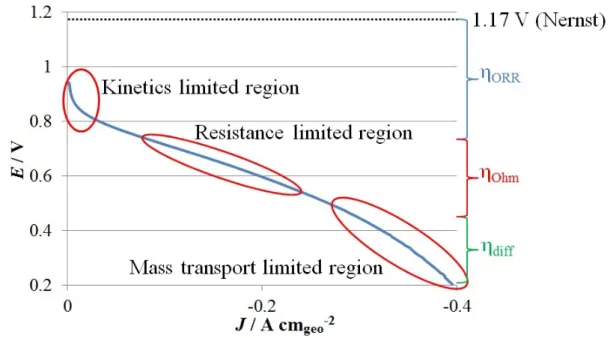
The impact of the above-mentioned problems can be illustrated by the voltage-current curve of PEMFCs (Figure 7). Every limitation leads to a voltage decrease, the so-called overpotentials. These overpotentials represent the loss of electrical work resulting from the conversion of chemical energy into heat. The voltage decrease of a fuel cell stem from three limitations: (i) the sharp decrease at high voltage and low current, ηORR, is due to the sluggish kinetics of the ORR, catalyzed by platinum
particles, i.e. the activation energy of the reaction is transformed into heat instead of electrical work; (ii) the linear decrease at moderate voltage and current, ηOhm,
is due to the resistance of the cell, e.g. the ionic resistance of the proton exchange membrane, which causes the conversion of chemical energy into heat by Joule effect; and (iii) the decrease at low voltage and high current is due to mass-transport limitations, e.g. the O2 diffusion inside the catalytic layer, leading again to energy (i.e. voltage) loss, ηdiff.
INTRODUCTION
Figure 7: Voltage-current curve of a commercial PEMFC.
Solutions
For the last decades, researchers investigated possible solutions to overcome the limitations of PEMFCs. In particular, significant resources were dedicated to the design of the catalysts for the ORR.
First, the catalytic activity of Pt/HSAC was improved. To do so, the deposition of platinum particles onto the carbon support had to be optimized. Indeed, the platinum particle size directly impacts the catalyst activity for the ORR, as the ORR is structure-sensitive [14–16]. Large platinum particles exhibit high specific activity for the ORR, i.e. high activity per platinum surface area. This high specific activity is due to large terraces, i.e. large facets, of platinum atoms at the surface of the particles which, like for bulk platinum, weakly bind the oxygenated intermediates of the ORR. When decreasing the particle size, the size of these terraces of platinum atoms decreases, leading to a higher proportion of platinum atoms at the edge sites, i.e. sites situated at the border of two facets, than at the terrace sites. The edge platinum atoms, which are low coordinated adsorption sites, bind more strongly the oxygenated intermediates of the ORR leading to a decrease of the activity. This is why the specific activity decreases with the size of the platinum particle, i.e. when increasing the proportion of edge platinum atoms [14–16]. However, another property of the platinum particles impacts the activity when focusing on the mass activity for the ORR, i.e. the activity expressed by mass unit of platinum. This property is the dispersion of platinum, i.e. the ratio between the number of platinum atoms at the surface of the particles and the total number of platinum atoms. The dispersion increases when the particle size decreases, leading to a higher proportion of platinum atoms at the particle surface, and so a higher number of active sites for
INTRODUCTION
the same amount of platinum. As the specific activity of platinum particles and the platinum dispersion are inversely related with the platinum particle size, the mass activity for the ORR, which is the combination of both phenomena, must reach a maximum with regard to the platinum particle size. This optimum is close to 3-4 nm [17, 18].
In order to further improve the activity for the ORR, the strength of the bond between the surface platinum atoms and the oxygenated intermediates of the ORR can be weakened by alloying platinum to transition metals (PtM), such as Cu, Co, Ni, etc. Indeed, as their atomic radius is smaller than that of platinum atoms, the introduction of transition metals within the platinum lattice leads to its contraction. The smaller platinum lattice parameter and the modified electronic structure of platinum atoms by the neighbour transition metal atoms lead to a widening of the d -band of platinum and a decrease of the average energy of the band, i.e. the d -band center [19–21]. This phenomenon, also called the strain-ligand effect, impacts the adsorption properties of oxygenated species, such as the oxygenated intermediates of the ORR, by modifying the platinum 5d -band [9, 22]. As explained in previous paragraphs, decreasing the energy of the bond between platinum active sites and oxygenated intermediates leads to an increase in the ORR activity.
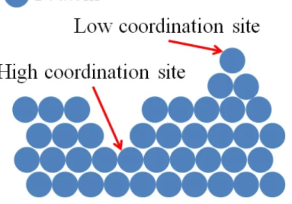
On this basis, two different ways of improvement of the activity for the ORR of PtM catalysts were explored by researchers. On the one hand, the increase in activity due to extended surface and well-defined facet catalysts was investigated. This way of improvement is based on Stamenkovic and co-workers’ study [23] which evidences the huge activity for the ORR of the Pt3Ni (1 1 1) facet. Stemming from this result, a lot of studies about very active structures with well-defined facets were conducted, e.g. octahedra [24, 25], nanoframes [26], nanostructured thin films [27], etc. On the other hand, researchers worked on the increase in activity by increasing the density of structural defects. These structural defects lead to the formation of low and high coordination active sites (schematically represented in Figure 8) and contracted and dilated structures. These particular active sites exhibit modified adsorption properties for the oxygenated species [28, 29]. As an example, low coordination active sites can strongly bind oxygenated intermediates of the ORR, leading on a decrease of the activity for the ORR, whereas high coordination active sites weakly bind the oxygenated intermediates, leading to an increase of the activity [30]. In order to increase the density of structural defects of particles, particular structures of nanoparticles were synthesized, such as nanoporous particles [31, 32], sponge particles [32–34], and hollow nanoparticles [32, 35–37].
After the catalytic activity for the ORR, the second property to improve was the stability of the catalysts, especially that of the metal nanoparticles. In order to investigate if alloying platinum with a transition metal, besides increasing the activ-ity, impacts the durability of the catalyst, many durability studies were performed on PtM catalysts [33, 34, 38–42]. From these studies, it is shown that the alloying of platinum with transition metals lowers the amount of dissolved platinum atoms, which leads to a mitigation of the particle dissolution, growth, and migration [12]. However, PtM catalysts may suffer from other stability issues. The major issue is
INTRODUCTION
Figure 8: Schematic representation of low and high coordination platinum sites.
the dissolution of the transition metal. When PtM catalysts are used in PEMFCs, this dissolution can decrease the performance of the fuel cell, as the transition metal atoms, responsible for the strain-ligand effect, are dissolved and leave the nanopar-ticles [13]. Moreover, the dissolved transition metal cations, which are not able to be reduced in PEMFCs medium, strongly interact with the sulfonated groups of the ionomer and the membrane. This strong interaction induces two major effects: (i) the proton-transport properties of the ionomer and the membrane degrade; and (ii) the mass-transport limitations of O2 molecules through the ionomer towards the active sites worsen [13, 43]. These impacts are mainly due to the blocking of the proton-conductive sites by the metal cations and to the degradation of the polymer, which is accelerated by metal cations. However, the morphology and structure of the nanoparticles after the dissolution of the transition metal can change, leading to particular types of structure and morphology [26, 31–34, 36, 37, 44–48]. These mor-phologies, such as hollow nanoparticles, display very good stability under PEMFC conditions, as they are formed after thousands of hours of PEMFC operation [35,49]. The combination of the good stability under PEMFC condition and the high ORR activity of such nanostructures, predominantly due to a high density of structural defects, pushed researchers to develop direct synthesis of nanostructured particles, such as hollow nanoparticles [32, 36, 37, 50, 51].
Concerning the architecture of the cathode catalytic layer, one possible solution is to replace the usual carbon supports, which are not optimal for the application in PEMFCs, by nanostructured carbons. Indeed, the diffusion of O2 molecules to-wards the active site of platinum particles is a key problem in PEMFCs (as already discussed in the previous section: Drawbacks of PEMFCs). The O2 diffusion prop-erties are strongly dependent of the pore texture of the catalytic layer, which stems from the structure of the carbon support and the manufacture conditions of the MEA (e.g. hot-pressing). The highly microporous structures of commonly used high surface area carbons are not optimal for the O2 diffusion within the catalytic layer. In order to improve mass transport inside this layer, other types of highly porous carbon support can be considered. For example, carbon xerogels (CXs) may be promising materials. CXs are meso-macroporous synthetic carbons with a pore texture which can be tuned from the synthesis variables. The synthesis of CXs via
INTRODUCTION
Figure 9: Schematic representation of the synthesis of carbon xerogel and SEM micrographs of two carbon xerogels with different textures. The micrographs are reproduced from Reference [60].
a sol-gel process is schematized in Figure 9 and can be summarized in four steps: (i) the polycondensation of resorcinol and formaldehyde in aqueous solution; (ii) the aging of the gel; (iii) the drying of the gel; and (iv) the pyrolysis of the polymer. Fig-ure 9 also shows scanning electron microscopy (SEM) micrographs of two CXs with different textures. As a synthetic material, CXs exhibit high purity and control-lable and reproducible pore texture [52]. When CXs are used as carbon support for PEMFC catalysts, their controllable and reproducible pore texture leads to catalytic layers with tailored architecture. This leads mitigating mass-transport limitations within the catalytic layer, resulting in better performance in PEMFCs [53]. More-over, previous works have demonstrated that CXs are excellent supports to deposit metals, especially platinum, with high dispersion [53–59].
Objectives of the thesis
The aim of this thesis is to combine several of the above-mentioned solutions in order to overcome the limitations of the ORR catalysts currently used at the cathode of PEMFCs. So, this thesis focused on the improvement of the PEMFC cathode catalytic layer performance by: (i) using a carbon support with a pore tex-ture suitable for the catalytic layer; (ii) developing synthesis methods for platinum nanoparticles supported on carbon xerogel (Pt/CX catalysts) with high platinum
INTRODUCTION
loading; (iii) developing synthesis methods for bimetallic PtCo nanoparticles sup-ported on carbon xerogel (PtCo/CX catalysts); and (iv) analyzing the activity and the durability of these catalysts both in liquid electrolyte and in real PEMFC.
To improve the mass-transport properties of the cathodic catalytic layer, a car-bon xerogel (CX) with appropriate pore texture was used as support for the catalytic particles. The deposition of platinum onto CX was then studied with the aim to synthesize highly loaded catalysts, i.e. 30-40 wt.% of platinum, with good disper-sion, i.e. platinum particle size around 3-4 nm, by means of the simplest possible synthesis method, i.e. which could be easily scaled up. In order to increase the catalytic activity for the ORR, methods to synthesize PtCo nanoparticles deposited on CX were then investigated. In particular, the synthesis of hollow PtCo/CX catalysts, which are supposed to exhibit high performance for the ORR and high durability in PEMFCs, was carried out. Finally, the activity for the ORR of the synthesized Pt/CX and PtCo/CX catalysts was measured in a three-electrode cell and the durability of the catalysts with the best performance was investigated in both a three-electrode cell system and a full PEMFC assembly.
Thesis outline
This thesis is structured around three axes: (i) the synthesis of platinum nanopar-ticles deposited on carbon xerogel (Pt/CX catalysts) for the oxygen reduction reac-tion (ORR) and its streamlining; (ii) the synthesis of PtCo nanoparticles (solid and hollow) deposited on carbon xerogel (PtCo/CX catalysts) for the ORR; and (iii) the study of the durability of the best catalysts synthesized in the two previous parts. Each axis is divided into two consecutive chapters.
In the first chapter, the platinum deposition on carbon xerogel via the so-called strong electrostatic adsorption (SEA) is studied. Based on previous works [54, 56–59], the synthesis of Pt/CX catalysts was modified in order to increase the platinum loading of the catalysts and decrease the platinum losses during the synthesis.
The second chapter focuses on a further streamlining of the platinum depo-sition process. Several Pt/CX synthesis methods were performed with the purpose of decreasing, or even avoiding completely, the platinum losses during the catalyst synthesis and/or speeding up the procedure. The electrochemical properties of these catalysts were compared to those of a commercial catalyst. Chapter 3 concerns the synthesis of PtCo particles deposited on carbon xerogel
(PtCo/CX catalysts) based on the SEA method.
In Chapter 4, the synthesis of hollow PtCo/CX catalysts is investigated and their electrochemical performance is compared to the same commercial catalyst as above.
INTRODUCTION
The penultimate chapter is dedicated to the durability study of the catalysts with the best performance for the ORR analyzed in the previous chapters. The durability of Pt/CX and hollow PtCo/CX catalysts was compared to that of the commercial catalyst in a three-electrode cell setup.
Finally, in Chapter 6, the durability of the catalysts with the best performance for the ORR is studied in situ, i.e. in full PEMFC assembly, and compared to that of two commercial catalysts assembled in the same conditions.
After the six chapters, a general conclusion and an outlook summarize the thesis and the future works to perform. At the end of the manuscript, an appendix intro-duces the reader to the electrochemical measurements (in three electrode cell or in PEMFC) performed all over the chapters.
This thesis regroups results either already published, submitted for publication, or in preparation for publication. Chapter 1 was published in Fuel cells [61]. Some of the results of Chapter 2 were published in Catalysts [62]. Chapter 2 has recently been submitted in its entirety to Applied Catalysis B: Environmental. Chapters 4 and 5 are in preparation for submission. Chapter 3 is not considered publishable as such and Chapter 6 has to be extended before publication since it mainly consists of preliminary results. As a consequence, the six chapters of this thesis can be read independently of each other, as each chapter is structured as an article.
REFERENCES
References
[1] H. Ibrahim and A. Ilinca, Techno-Economic Analysis of Different Energy Storage Technologies, in Energy Storage - Technologies and Applications, edited by A. Zobaa, chapter 1, InTech, 2013.
[2] I. Katsounaros, S. Cherevko, A. R. Zeradjanin, and K. J. J. Mayrhofer, Angewandte Chemie - International Edition 53, 102 (2014). [3] O. Z. Sharaf and M. F. Orhan, Renewable and Sustainable Energy Reviews
32, 810 (2014).
[4] Y. Wang, K. S. Chen, J. Mishler, S. C. Cho, and X. C. Adroher, Applied Energy 88, 981 (2011).
[5] G. Forozani, P. Shamshiri, and N. Sheikh, Journal of Fuel Cell Science and Technology 9, 034501 (2012).
[6] V. Stamenkovi´c, T. J. Schmidt, P. N. Ross, and N. M. Markovi´c, The Journal of Physical Chemistry B 106, 11970 (2002).
[7] V. Mehta and J. S. Cooper, Journal of Power Sources 114, 32 (2003). [8] J. K. Nørskov, J. Rossmeisl, A. Logadottir, L. Lindqvist, J. R.
Kitchin, T. Bligaard, and H. J´onsson, J. Phys. Chem. B. 108, 17886 (2004).
[9] I. E. L. Stephens, A. S. Bondarenko, U. Grønbjerg, J. Rossmeisl, and I. Chorkendorff, Energy & Environmental Science 5, 6744 (2012). [10] Y. Shao-Horn, W. C. Sheng, S. Chen, P. J. Ferreira, E. F. Holby,
and D. Morgan, Topics in Catalysis 46, 285 (2007).
[11] X. Z. Yuan, H. Li, S. Zhang, J. Martin, and H. Wang, Journal of Power Sources 196, 9107 (2011).
[12] S. Zhang, X. Z. Yuan, J. N. C. Hin, H. Wang, J. Wu, K. A. Friedrich, and M. Schulze, Journal of Power Sources 195, 1142 (2010).
[13] L. Dubau, L. Castanheira, F. Maillard, M. Chatenet, O. Lottin, G. Maranzana, J. Dillet, A. Lamibrac, J. C. Perrin, E. Moukheiber, A. Elkaddouri, G. De Moor, C. Bas, L. Flandin, and N. Caqu´e, Wiley Interdisciplinary Reviews: Energy and Environment 3, 540 (2014).
[14] M. Nesselberger, S. Ashton, J. C. Meier, I. Katsounaros, K. J. J. Mayrhofer, and M. Arenz, Journal of the American Chemical Society , 17428 (2011).
REFERENCES
[15] F. J. Perez-Alonso, D. N. McCarthy, A. Nierhoff, P. Hernandez-Fernandez, C. Strebel, I. E. L. Stephens, J. H. Nielsen, and I. Chorkendorff, Angewandte Chemie - International Edition 51, 4641 (2012).
[16] M. Shao, A. Peles, and K. Shoemaker, Nano Letters 11, 3714 (2011). [17] K. Kinoshita, Journal of the Electrochemical Society 137, 845 (1990). [18] O. Antoine, Y. Bultel, and R. Durand, Journal of Electroanalytical
Chemistry 499, 85 (2001).
[19] B. Hammer and J. K. Nørskov, Surface Science 343, 211 (1995).
[20] J. R. Kitchin, J. K. Nørskov, M. A. Barteau, and J. G. Chen, Journal of Chemical Physics 120, 10240 (2004).
[21] T. Bligaard and J. K. Nørskov, Electrochimica Acta 52, 5512 (2007). [22] I. E. L. Stephens, A. S. Bondarenko, F. J. Perez-Alonso, F.
Calle-Vallejo, L. Bech, T. P. Johansson, A. K. Jepsen, R. Frydendal, B. P. Knudsen, J. Rossmeisl, and I. Chorkendorff, Journal of the American Chemical Society 133, 5485 (2011).
[23] V. R. Stamenkovic, B. Fowler, B. S. Mun, G. Wang, P. N. Ross, C. A. Lucas, and N. M. Markovic, Science 315, 493 (2007).
[24] H. A. Gasteiger and N. M. Markovi´c, Science 324, 48 (2009).
[25] R. M. Ar´an-Ais, J. Solla-Gull´on, M. Gocyla, M. Heggen, R. E. Dunin-Borkowski, P. Strasser, E. Herrero, and J. M. Feliu, Nano Energy 27, 390 (2016).
[26] C. Chen, Y. Kang, Z. Huo, Z. Zhu, W. Huang, H. L. Xin, J. D. Snyder, D. Li, J. A. Herron, M. Mavrikakis, M. Chi, K. L. More, Y. Li, N. M. Markovic, G. A. Somorjai, P. Yang, and V. R. Stamenkovic, Science 343, 1339 (2014).
[27] D. Van Der Vliet, C. Wang, M. Debe, R. Atanasoski, N. M. Markovic, and V. R. Stamenkovic, Electrochimica Acta 56, 8695 (2011). [28] F. Calle-Vallejo, J. I. Mart´ınez, J. M. Garc´ıa-Lastra, P. Sautet,
and D. Loffreda, Angewandte Chemie - International Edition 53, 8316 (2014).
[29] F. Calle-Vallejo, J. Tymoczko, V. Colic, Q. H. Vu, M. D. Pohl, K. Morgenstern, D. Loffreda, P. Sautet, W. Schuhmann, and A. S. Bandarenka, Science 350, 185 (2015).
REFERENCES
[30] O. Le Bacq, A. Pasturel, R. Chattot, B. Previdello, J. Nelayah, T. Asset, L. Dubau, and F. Maillard, ChemCatChem 9, 2324 (2017). [31] L. Gan, M. Heggen, R. O’Malley, B. Theobald, and P. Strasser,
Nano Letters 13, 1131 (2013).
[32] R. Chattot, T. Asset, P. Bordet, J. Drnec, L. Dubau, and F. Mail-lard, ACS Catalysis 7, 398 (2017).
[33] S. Chen, H. A. Gasteiger, K. Hayakawa, T. Tada, and Y. Shao-Horn, Journal of the Electrochemical Society 157, A82 (2010).
[34] Y. Yu, H. L. Xin, R. Hovden, D. Wang, E. D. Rus, J. A. Mundy, D. A. Muller, and H. D. Abruna, Nano Letters 12, 4417 (2012).
[35] L. Dubau, J. Durst, F. Maillard, L. Gu´etaz, M. Chatenet, J. Andr´e, and E. Rossinot, Electrochimica Acta 56, 10658 (2011).
[36] L. Dubau, J. Nelayah, S. Moldovan, O. Ersen, P. Bordet, J. Drnec, T. Asset, R. Chattot, and F. Maillard, ACS Catalysis 6, 4673 (2016). [37] T. Asset, R. Chattot, J. Nelayah, N. Job, L. Dubau, and F.
Mail-lard, ChemElectroChem 3, 1591 (2016).
[38] S. Koh, M. F. Toney, and P. Strasser, Electrochimica Acta 52, 2765 (2007).
[39] H. R. Haas and M. T. Davis, ECS Transactions 25, 1623 (2009).
[40] L. Dubau, F. Maillard, M. Chatenet, J. Andr´e, and E. Rossinot, Electrochimica Acta 56, 776 (2010).
[41] F. Maillard, L. Dubau, J. Durst, M. Chatenet, J. Andr´e, and E. Rossinot, Electrochemistry Communications 12, 1161 (2010).
[42] A. Schenk, C. Grimmer, M. Perchthaler, S. Weinberger, B. Pich-ler, C. Heinzl, C. Scheu, F. A. Mautner, B. Bitschnau, and V. Hacker, Journal of Power Sources 266, 313 (2014).
[43] J. Durst, M. Chatenet, and F. Maillard, Physical Chemistry Chemical Physics 14, 13000 (2012).
[44] C. M. Pedersen, M. Escudero-Escribano, A. Vel´ azquez-Palenzuela, L. H. Christensen, I. Chorkendorff, and I. E. L. Stephens, Electrochimica Acta 179, 647 (2015).
[45] B. Han, C. E. Carlton, A. Kongkanand, R. S. Kukreja, B. R. Theobald, L. Gan, R. O’Malley, P. Strasser, F. T. Wagner, and Y. Shao-Horn, Energy & Environmental Science 8, 258 (2015).
REFERENCES
[46] S. Chen, W. Sheng, N. Yabuuchi, P. J. Ferreira, L. F. Allard, and Y. Shao-Horn, Journal of Physical Chemistry C 113, 1109 (2009).
[47] M. Oezaslan and P. Strasser, Journal of Power Sources 196, 5240 (2011). [48] M. Oezaslan, M. Heggen, and P. Strasser, Journal of the American
Chemical Society 134, 514 (2012).
[49] L. Dubau, M. Lopez-Haro, L. Castanheira, J. Durst, M. Chatenet, P. Bayle-Guillemaud, L. Gu´etaz, N. Caqu´e, E. Rossinot, and F. Maillard, Applied Catalysis B: Environmental 142-143, 801 (2013). [50] S. J. Bae, S. J. Yoo, Y. Lim, S. Kim, Y. Lim, J. Choi, K. S. Nahm, S. J.
Hwang, T.-H. Lim, S.-K. Kim, and P. Kim, Journal of Materials Chemistry 22, 8820 (2012).
[51] A. X. Shan, Z. C. Chen, B. Q. Li, C. P. Chen, and R. M. Wang, Journal of Materials Chemistry A 3, 1031 (2015).
[52] N. Job, R. Pirard, J. Marien, and J.-P. Pirard, Carbon 42, 619 (2004). [53] N. Job, J. Marie, S. D. Lambert, S. Berthon-Fabry, and P. Achard,
Energy Conversion and Management 49, 2461 (2008).
[54] S. D. Lambert, N. Job, L. D’Souza, M. Pereira, R. Pirard, B. Hein-richs, J. Figueiredo, J.-P. Pirard, and J. Regalbuto, Journal of Catal-ysis 261, 23 (2009).
[55] N. Job, B. Heinrichs, F. Ferauche, F. Noville, J. Marien, and J.-P. Pirard, Catalysis Today 102-103, 234 (2005).
[56] N. Job, M. F. R. Pereira, S. D. Lambert, A. Cabiac, G. Delahay, J.-F. Colomer, J. Marien, J. L. Figueiredo, and J.-P. Pirard, Journal of Catalysis 240, 160 (2006).
[57] N. Job, F. Maillard, J. Marie, S. Berthon-Fabry, J. P. Pirard, and M. Chatenet, Journal of Materials Science 44, 6591 (2009).
[58] N. Job, S. D. Lambert, M. Chatenet, C. J. Gommes, F. Maillard, S. Berthon-Fabry, J. R. Regalbuto, and J.-P. Pirard, Catalysis Today 150, 119 (2010).
[59] N. Job, M. Chatenet, S. Berthon-Fabry, S. Hermans, and F. Mail-lard, Journal of Power Sources 240, 294 (2013).
[60] N. Job, S. Berthon-Fabry, M. Chatenet, J. Marie, M. Brigaudet, and J. P. Pirard, Topics in Catalysis 52, 2117 (2009).
[61] A. Zubiaur, M. Chatenet, F. Maillard, S. D. Lambert, J.-P. Pirard, and N. Job, Fuel Cells 14, 343 (2014).
REFERENCES
[62] N. Job, S. D. Lambert, A. Zubiaur, C. Cao, and J.-P. Pirard, Catalysts 5, 40 (2015).
Chapter 1
Using the multiple SEA method
to synthesize Pt/carbon
xerogel electrocatalysts for
PEMFC applications
In the first chapter of this thesis, a method to synthesize Pt nanoparticles sup-ported on carbon xerogel with high Pt loading is developed. It starts from the strong electrostatic adsorption method, which allows the deposition of 8 wt.% of Pt with high dispersion on carbon xerogel. This method was repeated several times to increase the Pt loading, while trying to streamline the synthesis method in order to diminish the Pt losses. The results of this chapter are published in Fuel cells 14, 343 (2014).
1.1. INTRODUCTION
1.1
Introduction
The catalytic layers used in proton exchange membrane fuel cells (PEMFCs) are classically based on Pt particles supported on carbon black (Pt/CB). The structure of these catalytic layers is however not optimal, resulting in incomplete utilization of the mass of Pt loaded onto the carbon support [1]. In order to reduce the cost of the catalytic layer without decreasing its performance, two parameters can be improved: the support and the synthesis of the Pt particles.
With respect to the support, the commonly used carbon blacks do not display optimal properties for electrocatalysis: they may contain high amount of chemical impurities, and the final structure of the electrodes is hardly tuneable [2]. A possible solution to these drawbacks is to use synthetic nanostructured materials with a controllable, reproducible texture and with a pure, known and constant chemical composition; carbon xerogels (CXs) exhibit such properties [3]. With respect to the Pt crystallites, a decrease of the particle size to nanometre dimensions allows increasing the ratio between the number of atoms on the surface to the overall number of metal atoms (the so-called dispersion), thereby heightening the mass activity (per gram of metal), and thus decreasing the cost of the catalytic layers. However, increasing the dispersion also results in a decrease in the specific activity of the Pt nanoparticles (per real cm2 of Pt) for most of the reactions performed
in PEMFCs [4]. This trend has been attributed to increased adsorption strength of oxygenated species for smaller Pt particle size, as shown from X-ray absorption spectroscopy studies [5]. As a result, the optimal mass activity is obtained for Pt nanoparticles of 3 nm in diameter [6, 7].
Highly dispersed Pt/CX catalysts can be prepared by the strong electrostatic ad-sorption (SEA) method [8, 9]. The SEA technique [8, 10, 11] consists in maximizing the electrostatic interactions between the metal precursor and the support by ad-justing the pH of the carbon/water/Pt precursor slurry to the adequate value. The latter depends on the surface chemistry (and of the point of zero charge, PZC) of the support and on the nature of the Pt precursor. Due to the presence of various oxygen surface groups, the carbon support protonates/ deprotonates at low/high pH value, thus enhancing the adsorption of anions/cations, respectively. For instance, in the case of the impregnation of CXs with chloroplatinic acid (CPA, H2PtCl6) aqueous solutions (1,000 ppmPt), the final pH leading to the highest Pt uptake was found
to be ca. 2.5, yielding electrocatalysts with Pt mass fraction close to 10 wt.% [10]. However, achieving high Pt weight percentage without sacrificying the catalytic performance requires multiple ’impregnation-drying-reduction’ cycles [9]. A major hurdle with this technique is the use of large volumes of fresh 1 gPt L−1 solution for
each impregnation step, which induces inacceptable losses of Pt. In order to improve the synthesis efficiency, efforts were targeted so as to reuse the same Pt solution for several impregnation steps (multiple SEA method).
The present chapter is focused on the synthesis and characterization of Pt/CX nanoparticles by the multiple SEA method in view of testing and using them as PEMFC catalysts.
1.2. EXPERIMENTAL
Figure 1.1: Characterization of the CX pore texture obtained from mercury porosimetry. Cumulative pore volume as a function of the pore size in the mesopores domain.
1.2
Experimental
1.2.1
Synthesis
The support used in this thesis is a CX prepared by drying and pyrolysis of a resorcinol-formaldehyde gel [12]. Briefly, the gel was obtained by polycondensation of resorcinol with formaldehyde in water. The pore size distribution of this CX was centred at 80 nm (Figure 1.1): the resorcinol/formaldehyde molar ratio, R/F, was fixed at 0.5, the resorcinol/sodium carbonate molar ratio, R/C, was chosen to be equal to 1,000 and the dilution ratio, D, i.e. the solvent/(resorcinol and formaldehyde) molar ratio, was set at 5.7. At first, 114.1 g of resorcinol and 0.11 g of sodium carbonate (Na2CO3) were mixed with 217.5 mL of deionized water in a 500 mL vessel under stirring. The addition of sodium carbonate fixes the pH at 5.85. After dissolution of resorcinol, 169.2 g of formaldehyde solution (37 wt.% in water, stabilized with 10-15 wt.% of methanol) were added. Then, the flask was sealed and put in an oven at 358 K for gelling and aging. After 72 h, the obtained gel was dried under vacuum: the bottle was opened and heated to 333 K; then the pressure was decreased stepwise during 8 h until it reached 1,200 Pa. At this low pressure, the flask was heated up to 423 K and left at this temperature for 12 h. When the sample was dry, it was pyrolyzed at 1,073 K under nitrogen flow following this procedure: (i) heating at 1.7 K min−1 up to 423 K and hold for 15 min; (ii) heating at 5 K min−1 up to 673 K and hold for 1 h; (iii) heating at 5 K min−1 up to 1,073 K and hold for 2 h; and (iv) progressively cooling down to room temperature. After pyrolysis, the xerogel was crushed and sieved between 75 and 250 µm.
1.2. EXPERIMENTAL
To synthesize Pt/CX catalysts, the ’multiple SEA method’ was used. In a pre-vious study [9], in order to obtain high Pt weight percentage, the SEA method was performed up to three times on the same support using a new H2PtCl6 solution each time. In ’multiple SEA’, the precursor solution is highly loaded in order to reuse it several times to increase the catalyst Pt weight percentage. Concerning the initial concentration of the H2PtCl6 solution, Lambert et al. [10] showed that the quantity of Pt adsorbed on the surface of CXs does not depend on the concentration of the H2PtCl6 initial solution, should it be above 5 mmol L−1 (i.e. around 1 gPt L−1). As
a result, one can use highly concentrated H2PtCl6 solution without modifying the Pt deposition.
One gram of CX powder was mixed with 567 mL of an H2PtCl6 solution at 8.97 mmol L−1 (i.e. 1.75 gPt L−1) with an initial pH of 2.5. The surface loading
(SL), i.e. the total area of CX surface in solution, was equal to 1,000 m2L−1 and the
concentration of H2PtCl6 was chosen high enough to reuse the solution five times. After 1 h of stirring, the mixture was filtered and the filtrate was kept for reuse in another impregnation step. The solid was dried in an oven at 333 K during 12 h. Then, the dried CX was reduced at 473 K under H2 flow (0.04 mmol s−1) during 1 h to obtain carbon-supported Pt nanoparticles (Pt/CX). In order to synthesize several catalysts with various Pt weight percentages, the ’impregnation-drying-reduction’ steps were performed from one to five times on the same support. After the last impregnation, each catalyst was reduced at 723 K under H2 (0.04 mmol s−1) during 5 h to clean the surface of the Pt particles from chlorine [9]. Hereafter, the five catalysts are labeled according to the number of ’impregnation-drying-reduction’ cycles, e.g. Pt-1/CX for the catalyst obtained after one cycle, Pt-2/CX for the catalysts obtain after two cycles, etc.
1.2.2
Physicochemical Characterization
The textural properties of the CX support were determined by N2 adsorption-desorption and mercury porosimetry. The nitrogen adsorption-adsorption-desorption isotherms were measured at 77 K with a Sorptomatic CE Instruments 1990 Series. Before the measurement, the sample was outgassed at 10−3 Pa during 12 h at room temper-ature. The isotherm analysis provided the BET specific area, SBET, the
microp-orous volume calculated with the Dubinin-Radushkevich equation, VDUB, and the
cumulative volume of pores with width between 2 and 7.5 nm determined by the Broekhoff-de Boer theory, Vcum<7.5 nm [13]. The mercury porosimetry measurement
was performed with a Pascal Series 140 porosimeter between 0.01 and 0.4 MPa and with a Pascal Series 240 porosimeter between 0.1 and 200 MPa. This measurement provided the volume of pores with width higher than 7.5 nm, VHg. The total void
volume, Vv, was calculated from the combination of nitrogen adsorption-desorption
isotherm and mercury porosimetry measurement [14, 15]:
1.2. EXPERIMENTAL
The pore size distribution was determined from the mercury porosity measure-ment by applying Washburn’s theory [16] because CXs do not crush under the mercury pressure and undergo intrusion only [3, 12, 17].
The Pt weight percentage of the catalysts was measured by inductively coupled plasma-atomic emission spectrometry (ICP-AES) using an ICAP 6500 THERMO device. The solution for the analysis was prepared as follows: a fraction of the catalyst sample was weighed and digested by 10 mL of sulphuric acid (H2SO4) and 5 mL of nitric acid (HNO3), and this solution was heated at 573 K until clear. After the complete dissolution of the carbon support and evaporation, 3 mL of hydrochloric acid (HCl) and 1 mL of HNO3 were added. The obtained solution was heated a few minutes at 393 K, and transferred into a 50 mL calibrated flask, which was finally filled by deionized water.
The Pt particles were observed by transmission electron microscopy (TEM) with a Jeol 2010 transmission electron microscope (200 kV, LaB6 filament). A carbon-coated copper grid was cleaned in ethanol and dried before being contacted with the Pt/CX catalyst powder. Some particles of Pt/CX catalysts remained attached to the grid through electrostatic interaction. Pt nanoparticle size distribution histograms were obtained by image analysis of the TEM micrographs on at least 500 particles [9]. The catalyst powders were analyzed by X-ray diffraction (XRD) with a Siemens D5000 goniometer using the CuKα line (Ni filter).
1.2.3
Electrochemical Characterization
Material All the glassware was cleaned by immersion in a H2SO4:H2O2 solution overnight and thoroughly rinsed with ultrapure water (18 MΩ cm). The electrolytic solutions were prepared from ultrapure water and H2SO4 (98% Suprapur, Merck).
Catalytic layer preparation To measure the electrochemical properties of the catalysts, inks were first prepared. The ink composition was chosen to keep the amount of carbon constant, regardless of the metal loading [18,19]. For each sample, the amount of catalyst containing 19.8 mg of CX was crushed in a mortar then mixed with 755 mg of ultrapure water and 466 mg of 5 wt.% Nafion® solution. In order to blend it homogeneously, the mixture was then processed in an ultrasonic bath for 30 min. Once the ink was homogeneous, 10 µL of ink were deposited on a glassy carbon (GC) disk (5 mm in diameter) and sintered at 423 K during 15 min to evaporate the solvents and stick the catalyst onto the GC disk. The catalytic layer deposited on the GC disk composes the working electrode for all electrochemical measurements. This procedure yields active layers of identical thickness onto the GC disk (i.e. resulting in identical mass-transport limitations within the layer [18, 19]).
1.2. EXPERIMENTAL
Electrolyte and wetting procedure During all measurements, the working elec-trode was immersed in an electrolyte constituted of 1 M H2SO4 aqueous solution, which should ensure full wetting of the metallic particles by the electrolyte [19]. In order to ensure that all the pores, i.e. both the extragranular and the mesoporous intergranular porosities, were fully filled, a drop of electrolyte was deposited onto the catalytic layer. Then, the electrode was put under vacuum in order to out-gas the layer by bubbling air through the drop. Once no air bubbles were visible, the electrode and the drop were put back under atmospheric pressure so that the electrolyte filled the empty porosity of the layer. This wetting procedure ensures that the catalyst wetting is complete and that the Pt utilization factor is close to 100%. Indeed, previous works [9, 19] performed on similar systems showed good consistency between the Pt specific surface area measured after using this wetting procedure and the surface calculated from TEM micrographs. Finally, the electro-chemical measurements were usually steady, which also hints at good wetting of the layer.
If needed, the following measurement techniques are explained with more details in the Appendix A1 at the end of this thesis.
CO stripping voltammetry The Pt specific surface area was measured by CO stripping voltammetry [20–22]. The procedure was initiated by the application of a steady potential of 0.1 V vs. normal hydrogen electrode (NHE) to the working electrode, while gaseous CO was bubbled in the electrolyte solution for 6 min. After an Ar purge of 39 min in order to remove the CO dissolved in the electrolyte (still at 0.1 V vs. NHE), the CO chemisorbed at the surface of the particles was electroox-idized into CO2 by increasing the electrode potential from 0.05 to 1.23 V vs. NHE at 20 mV s−1. The potential was then cycled between 0.05 and 1.23 V vs. NHE at the same scan speed for two more cycles. This results in three recorded cycles, i.e. the first cycle in which the peaks from the CO electrooxidation occur and two other cycles which are cyclic voltammetry cycles performed at 20 mV s−1, as all the adsorbed CO was electrooxidized during the first cycle. As the third cycle represents the background of the CO stripping measurement, it is subtracted from the first in order to isolate the CO electrooxidation peak. The Pt specific surface area, SCO
(m2 gPt−1), was calculated from the CO oxidation peak current, assuming that the
electrooxidation of a full monolayer of COad requires 420 × 10−2 C mPt−2 [23].
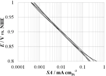
Activity for the oxygen reduction reaction The specific activity of the cat-alysts for the oxygen reduction reaction (ORR) was measured on a rotating disk electrode (RDE). After saturation of the electrolyte by oxygen bubbling during 15 min, the electrode potential was set at 1.09 V vs. NHE and then decreased at 1 mV s−1 to 0.25 V vs. NHE, while measuring the reduction current. This mea-surement was repeated at various rotation speeds of the electrode (400, 900, 1600, and 2500 rpm). For each rotation speed of the electrode, the kinetic current was calculated by correcting the measured current for the effect of the external mass
![Figure 5: Scheme of a fuel cell stack (adapted from Reference [7]).](https://thumb-eu.123doks.com/thumbv2/123doknet/6670712.182824/21.892.130.747.133.470/figure-scheme-fuel-cell-stack-adapted-reference.webp)