HAL Id: tel-00527528
https://tel.archives-ouvertes.fr/tel-00527528
Submitted on 19 Oct 2010
HAL is a multi-disciplinary open access
archive for the deposit and dissemination of
sci-entific research documents, whether they are
pub-lished or not. The documents may come from
teaching and research institutions in France or
abroad, or from public or private research centers.
L’archive ouverte pluridisciplinaire HAL, est
destinée au dépôt et à la diffusion de documents
scientifiques de niveau recherche, publiés ou non,
émanant des établissements d’enseignement et de
recherche français ou étrangers, des laboratoires
publics ou privés.
Application à la conception d’une table actionnée pour
la micromanipulation en milieu liquide.
Cyrille Lenders
To cite this version:
Cyrille Lenders. Etude du comportement mécanique des microbulles. Application à la conception
d’une table actionnée pour la micromanipulation en milieu liquide.. Automatique / Robotique.
Uni-versité de Franche-Comté, 2010. Français. �tel-00527528�
Année : 2010
THÈSE
présentée à
L’U.F.R. DES SCIENCES ET TECHNIQUES
DE L’UNIVERSITÉ DE FRANCHE-COMTÉ
pour obtenir le
GRADE DE DOCTEUR DE L’UNIVERSITÉ
DE FRANCHE-COMTÉ
en A
UTOMATIQUE(Ecole Doctorale Sciences Physiques pour l’Ingénieur et Microtechniques)
Etude du comportement mécanique des microbulles.
Application à la conception d’une table actionnée
pour la micromanipulation en milieu liquide
par
Cyrille Lenders
Soutenue le 2 Septembre 2010
devant la Commission d’Examen :
Président:
Gérard D
EGREZProfesseur, Université libre de Bruxelles
Rapporteurs :
Charles B
AROUDProfesseur, Ecole Polytechnique
Enrico F
ILIPPIProfesseur, Faculté Polytechnique de Mons
Examinateur :
Pierre C
OLINETChercheur Qualifié F.R.S.- FNRS, Université libre de Bruxelles
Directeurs de thèse :
Nicolas C
HAILLETProfesseur, Université de Franche-Comté
Pierre L
AMBERTProfesseur, Université libre de Bruxelles
Co-directeurs de thèse :
Michaël G
AUTHIERChargé de Recherche CNRS, FEMTO-ST/AS2M
Alain D
ELCHAMBREProfesseur, Université libre de Bruxelles
Résumé
Cette thèse a pour contexte la micromanipulation en milieu liquide. Cette thématique scien-tifique vise à comprendre les phénomènes qui interviennent lors de la manipulation dans un liquide de microcomposants, dont la taille peut varier entre 1 µm et quelques millimètres. Les travaux de cette thèse se sont focalisés sur l’étude des forces de tension de surface en milieu immergé, car elles bénéficient d’effets d’échelle favorables. L’idée poursuivie est d’utiliser des bulles de gaz comme un moyen d’actionnement dans les milieux liquides, et nécessite d’étudier les propriétés mécaniques de ces bulles. L’originalité de l’approche repose sur la combinaison de deux effets : la tension de surface et la compressibilité du gaz.
La première étape a été l’étude d’un moyen efficace pour générer une unique bulle de gaz de taille voulue. Après une analyse exhaustive, il est apparu que la génération de bulle par le contrôle en volume était une méthode prometteuse. Nous avons alors développé un modèle permettant de prédire la taille d’une bulle, et mis en évidence la possible existence d’une instabilité de la croissance de ces bulles. Une étude analytique adimensionnelle nous a permis de définir un critère pour prédire l’existence ou non de cette instabilité.
La seconde étape a porté sur la caractérisation mécanique en régime quasi statique d’une bulle de gaz en contact avec deux solides. Le but étant de prédire la force générée par une bulle de gaz sur les solides ainsi que sa raideur. Le modèle implémenté a permis de déduire des propriétés intéressantes des bulles de gaz, notamment une grande compliance dont la valeur peut être contrôlée par des paramètres fluidiques. Cette propriété de compliance étant très recherchée en micromanipulation, un démonstrateur exploitant les bulles de gaz a été conçu. Il s’agit d’une microtable compliante actionnée par trois bulles. Ces travaux ouvrent la voie vers de nouveaux modes d’actionnement ou de capteur utilisant la transduction entre une énergie fluidique et mécanique opérée par un ménisque capillaire.
Abstract
The scope of this thesis is micromanipulation in liquid media. This scientific field aims at understanding the relevant phenomena existing during the manipulation in a liquid of microcomponents having a size between 1 µm and a few millimeters. This work focuses on the study of surface tension forces in immersed media, because they have favorable scaling effect. The main idea is to use gas bubbles as actuation mean in a liquid, and requires to study the mechanical properties of these bubbles. The originality of the approach is the combination of two effects: surface tension and gas compressibility.
The first step was the study of an efficient mean to generate a single bubble of predefined size. After a detailed review, it appeared that volume controlled bubble generation was a promising method. We have then developed a model to predict the size of a bubble, and emphasized the possible existence of a growing instability. An analytic dimensionless study allowed to define a criterion to predict the existence of this instability.
The second step aimed at the mechanical characterization in quasi static equilibrium of a gas bubble caught between two solids. The purpose is to predict the force generated by the bubble, together with its stiffness. The model implemented allowed to infer interesting properties, notably a high compliance whose value is controllable by fluidic parameters. This compliance property being very important during micromanipulation, a demonstrator making use of gas bubbles has been designed and manufactured. It consists in a compliant microtable actuated by three bubbles. This work opens the way to new actuation or sensing means, using the transduction between fluidic and mechanic energy operated by a capillary bridge.
Remerciements
La thèse est un parcours enrichissant mais semé d’embûches, à l’issue duquel l’un des ap-prentissages majeur est d’entrevoir l’étendue de notre ignorance. Au terme de ces années de recherche, on ne peut que ressentir de la frustration de ne pas avoir eu le temps d’ouvrir toutes les portes qui s’offraient à nous, mais les connaissances engrangées et les compétences acquises en valaient la peine.
De nombreuses personnes ont contribué à enrichir ces années. Je tiens en premier lieu à remercier Pierre Lambert et Michaël Gauthier pour les nombreux conseils qu’ils ont pu me prodiguer pour mener à bien ce travail. Leurs avis, leur aide et leur soutien m’ont toujours été précieux.
Je tiens également à remercier Alain Delchambre et Nicolas Chaillet pour m’avoir accueilli dans leur laboratoire et m’avoir fait confiance en me donnant l’opportunité de réaliser cette thèse.
Je remercie Messieurs Baroud, Colinet, Degrez et Filippi, d’avoir accepté de siéger dans mon jury de thèse. J’ai beaucoup apprécié leurs remarques pertinentes et les confrontations de point de vue. J’espère que les idées développées dans ce travail pourront leur être utiles. Je remercie le Bureau des Relations Internationales de l’ULB ainsi que le crédit Tournesol du WBI, pour m’avoir aidé à financer mes séjours à Besançon.
Mes pensées vont également à mes collègues, tant à Bruxelles qu’à Besançon. L’excellente ambiance qui règne au sein des équipes a donné lieu à de nombreuses discussions intéressantes, et m’a permis de conserver un certain optimisme lorsque les difficultés s’amoncelaient. Je remercie en particulier Aline, qui a eu la force de supporter mes plaintes incessantes, et Jean-Baptiste, pour sa vision toujours originale des choses.
Je remercie Julien, d’avoir accepté de relire le manuscrit et d’avoir ainsi évité certains quiproquos résultants de tournures de phrase malheureuses.
D’une manière générale, je remercie aussi tous ceux qui ont réussi à me faire oublier que je ne parviendrai pas à terminer ce travail dans les temps.
Enfin, je tiens à remercier tous mes proches pour leur soutien moral lors de ces dernières années. En particulier, je remercie Evelyne, mon épouse, pour m’avoir épaulé et surtout m’avoir supporté pendant ces derniers mois. Merci de ne pas m’avoir tenu rigueur d’avoir si souvent ramené mes frustrations et mes doutes à la maison, et d’avoir su me rassurer.
Contents
1 Introduction 1
1.1 Microworld: Stakes and Challenges . . . 1
1.1.1 Scaling Laws . . . 2
1.2 Introduction to Micro-Assembly . . . 3
1.3 Introduction to Micro-Assembly in Liquid Media . . . 5
1.4 Objectives of the Thesis . . . 5
1.5 Manuscript Layout and Reading Suggestion . . . 6
1.5.1 Reading Suggestion . . . 6
1.6 Thesis Joint Supervision . . . 7
I
Review of Forces Acting on Immersed Microsystems
9
2 Microforces Modeling 11 2.1 Study of Forces in Microsystems . . . 112.1.1 Force Models . . . 11
2.1.2 Similarity Laws . . . 12
2.2 Review of Major Forces Acting in Liquid Media . . . 13
2.2.1 Electro-Hydrodynamic Forces . . . 14
2.2.2 Hydrodynamic Forces . . . 16
2.2.3 Surface Tension Forces . . . 16
2.3 Example of Microvalves . . . 17
2.3.1 Devices with a Moving Part . . . 18
2.3.2 Devices Without Moving Part . . . 18
2.4 Conclusions . . . 19
3 About Surface Tension 21 3.1 Origin of Surface Tension Forces . . . 21
3.1.1 Surface Energy . . . 21
3.1.2 Wettability . . . 23
3.2 Modeling Surface Tension . . . 24
3.2.1 Surface Tension Force . . . 25
3.2.2 Pressure drop Across Interface . . . 26
3.2.3 Capillary Force . . . 27
3.3 Measuring Surface Tension . . . 28
3.3.1 Capillary Rise . . . 29
3.3.2 Detachment Methods . . . 29
3.3.3 Use of drops or bubbles . . . 30
3.4 Influencing Parameters . . . 31
3.4.1 Temperature . . . 31
3.4.2 Contamination . . . 32
3.4.3 Electrowetting . . . 33
3.5 Implications for Microsystems . . . 33
3.5.1 Crossing the Free Surface of a Liquid . . . 33
3.5.2 Statistical Self Assembly of Microcomponents . . . 34
3.5.3 Bubbles Preventing Solid Contact . . . 35
3.6 Conclusion . . . 35
II
Study and Application of Surface Tension Forces in Liquid
Media
37
4 Controlled Generation of a Gas Bubble 39 4.1 Bubble Generation Mean . . . 394.1.1 Electrolysis . . . 40
4.1.2 Cavitation . . . 42
4.1.3 Thermal Growth . . . 43
4.1.4 Pressure Controlled Gas Injection . . . 44
4.1.5 Volume Controlled Gas Injection . . . 47
4.1.6 Comparison of the Different Generation Means . . . 48
4.2 Model of the Volume Controlled Generator . . . 50
4.2.1 Gas Bubble in Liquid Media . . . 50
4.2.2 Device Description . . . 51
Contents iii
4.2.4 Limit of the Model . . . 55
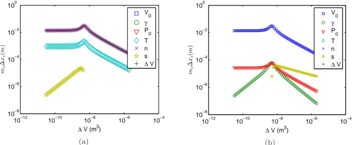
4.2.5 Parameters Sensitivity . . . 56
4.2.6 Dimensionless Analysis and Stability Criterion . . . 60
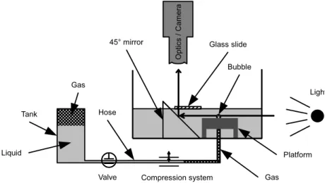
4.3 Experimental Validation of the Volume Controlled Bubble Generation Model 66 4.3.1 First Experimental Setup . . . 66
4.3.2 Second Experimental Setup . . . 75
4.3.3 Conclusion of Experimental Validation . . . 77
4.4 Examples of Application . . . 81
4.4.1 Pressure Sensor . . . 81
4.4.2 Bubble as Compliant Actuator . . . 82
4.5 Conclusions . . . 83
5 Compliance of a Gas Bubble 85 5.1 Modeling the Compliance of a Gas Bubble . . . 85
5.2 Description of the Prototype . . . 86
5.2.1 Application Context . . . 86
5.2.2 Design of the Prototype . . . 88
5.2.3 Device Advantages . . . 93
5.3 Force Generated by a Gas Bubble . . . 95
5.3.1 Hypothesis . . . 95
5.3.2 Equations . . . 96
5.3.3 Determination of Bubble Profile . . . 97
5.3.4 Application of the Model . . . 99
5.3.5 Limitation of the Model . . . 100
5.3.6 Analysis of the Model . . . 101
5.3.7 Parabolic Approximation . . . 114
5.4 Validation of the Model . . . 119
5.4.1 First Experimental Trials . . . 119
5.4.2 Validation Strategy . . . 120
5.4.3 Test Bed Design . . . 121
5.4.4 Technological Issues . . . 122
5.4.5 Methodology for Results Analysis . . . 128
5.4.6 Experimental Results . . . 131
5.4.7 Conclusion on the Experimental Results . . . 133
5.5.1 Layout of the device . . . 136
5.5.2 Manufacturing . . . 136
5.5.3 Lateral Forces . . . 137
5.6 Conclusions . . . 138
6 Perspectives and Conclusions 139 6.1 Prospective Developments . . . 139
6.1.1 Controlled Microtable . . . 139
6.1.2 Dynamics of the Table . . . 140
6.1.3 Non Axisymmetric Bubbles . . . 142
6.2 Conclusions . . . 142
A Demonstration of Jurin’s Law 145 B Construction of Fifth Order Polynomial Modeling Volume Controlled Bub-ble Generator 147 C Demonstration for Equality of Forces Along Bubble Profile 149 D Demonstration for Nullity of Force for Part-Spherical Profiles 151 E Complements About Forces Acting on Immersed Microcomponents 153 E.1 Electrophoresis . . . 153
E.2 Dielectrophoresis . . . 154
E.3 Hydrodynamic Forces . . . 154
List of Figures
1.2.1 View of ruby balls repelling one another . . . 4
1.3.1 View of the Pronomia micro-assemblia station . . . 5
2.2.1 Electrophoresis: ionic layers . . . 15
2.2.2 Pressure in a Stokes flow . . . 17
3.1.1 Illustration of surface tension . . . 22
3.1.2 Origin of surface tension . . . 22
3.1.3 Illustration of Young-Dupré equilibrium equation . . . 24
3.1.4 Illustration of static, advancing and receding angles . . . 24
3.1.5 Illustration of fluid anchoring . . . 25
3.2.1 Geometric definition of mean curvature . . . 26
3.2.2 Origin of the pressure force in surface tension modeling . . . 27
3.2.3 Illustration of capillary forces self centering property . . . 28
3.3.1 Illustration of liquid rise in a capillary tube . . . 29
3.3.2 Surface tension measurement by Wilhelmy method . . . 30
3.3.3 Surface tension measurement using drops or bubbles . . . 31
3.4.1 Evolution of water surface tension with respect to temperature . . . 32
3.5.1 View of a piezoelectrically actuated microgripper . . . 34
3.5.2 Statistical self assembly using surface functionalization . . . 35
3.5.3 Microbubbles preventing the contact between two solids . . . 36
4.1.1 Concept of a single bubble generator . . . 40
4.1.2 Electrode used for electrolysis based bubble generator testing . . . 42
4.1.3 Working principle of the pressure controlled bubble generator . . . 44
4.1.4 Height of a bubble with a pressure controlled generator . . . 45
4.1.5 View of the pressure regulator used in the pressure controlled bubble generator 46 4.1.6 Working principle of the volume controlled bubble generator . . . 47
4.2.1 Influence of surface tension and amount of gas mole on the diameter of a free
gas bubble . . . 51
4.2.2 Schematic representation of the volume controlled bubble generator . . . 52
4.2.3 Model of the volume controlled bubble generator . . . 52
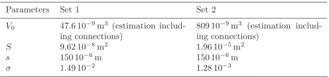
4.2.4 Bubble height in a volume controlled generator, first set of parameters . . . . 55
4.2.5 Bubble height in a volume controlled generator, second set of parameters . . 56
4.2.6 Evolution of mi∆xi with ∆V for first set of parameters . . . . 58
4.2.7 Evolution of mi∆xi with ∆V for second set of parameters . . . . 59
4.2.8 Numerical dimensionless threshold for bubble growth instability . . . 62
4.2.9 Contour plot of ∂ bV /∂eh with respect to eh and eE, in the case eP = 10 . . . . . 64
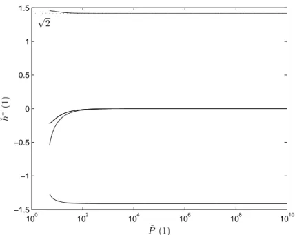
4.2.10eh∗ function of eP . . . . 65
4.2.11Analytical σ threshold . . . . 66
4.2.12Analytical dimensionless threshold between stable and unstable bubble gener-ation . . . 67
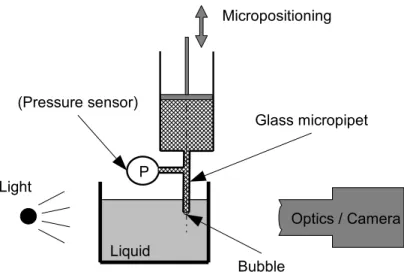
4.3.1 Schematic representation of the first experimental setup for the validation of the volume controlled bubble generation model . . . 68
4.3.2 View of the connection to the pressure sensor . . . 69
4.3.3 Illustration of the image analysis software . . . 70
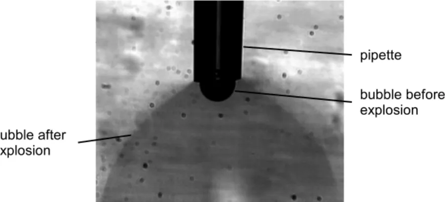
4.3.4 View of bubble growth instability . . . 70
4.3.5 Experimental validation of the volume controlled bubble generator, first setup, first set of parameters . . . 71
4.3.6 Experimental validation of the volume controlled bubble generator, first setup, second set of parameters . . . 72
4.3.7 Comparison of pressure measurement with pressure sensor and by image analysis 74 4.3.8 Schematic view of the second experimental setup used to validate the volume controlled bubble generation model . . . 75
4.3.9 View of a large bubble: it does not comply with the hypothesis of part-spherical shape . . . 76
4.3.10Calibration of the compression system of second experimental setup . . . 77
4.3.11Experimental results on the second test bed . . . 79
4.3.12Summary of experimental validations . . . 80
4.4.1 Height of a bubble with respect to pressure and channel diameter . . . 82
4.4.2 Schematic view of a bubble based pressure sensor . . . 83
4.4.3 Illustration of the relation between laser beam displacement and pressure to measure . . . 84
4.4.4 Illustration of volume controlled generation with two outlet channels having a different diameter . . . 84
List of Figures vii
5.1.1 Modeling a bubble as a spring . . . 86
5.2.1 Spring hold compliant table . . . 87
5.2.2 Illustration of the efficiency of a compliant table during the "peg in hole" benchmark test . . . 88
5.2.3 Illustration of an orthoplanar spring . . . 89
5.2.4 Schematic view of the bubble supported compliant table . . . 90
5.2.5 Illustration of the simple and improved anchoring methods . . . 90
5.2.6 Dimensions of prototype tables . . . 91
5.2.7 Actual view of two tables . . . 91
5.2.8 View of a table with improved anchoring circle manufactured on a CNC milling machine . . . 92
5.2.9 View of the three actuated DOF . . . 93
5.2.10Illustration of the working principle of the compliant table device . . . 94
5.3.1 Geometry of bubble between two solids . . . 95
5.3.2 Free Body Diagram of the table around one bubble . . . 96
5.3.3 Free body diagram in the case of through holes . . . 97
5.3.4 View of input and output parameters of the model . . . 98
5.3.5 View of the iterative procedure to calculate bubble profile . . . 99
5.3.6 Pressure repartition in the case of a table with blind holes or through holes . 100 5.3.7 Evolution of surface tension force and pressure force along symmetry axis (z) with the gap . . . 103
5.3.8 Illustration of the effect of total gas volume variation . . . 104
5.3.9 Comparison of bubble profiles obtained with blind holes and through holes . 106 5.3.10Evolution of the force and contact angles for different gas volumes when using a table with through holes . . . 107
5.3.11Comparison of bubble profiles and force obtained for different table hole di-ameters . . . 109
5.3.12Comparison of the force with respect to gap distance for a scaled model . . . 112
5.3.13Design flow chart for compliant table . . . 113
5.3.14Illustration of parabolic approximation of bubble profile . . . 114
5.3.15Illustration of the profiles obtained by ODE calculation and parabolic approx-imation . . . 117
5.3.16Evolution of the mean curvature and force at both ends of the parabolic ap-proximation profile, compared to ODE resolution . . . 118
5.4.1 View of the prism used to perform force measurement in water with an AFM 120 5.4.2 Methodology of bubble force measurement using an AFM . . . 120
5.4.4 Views of the bubble and the AFM tip used to measure the force generated by
a bubble . . . 121
5.4.5 View of an approach-recede curve to estimate qualitatively the force generated by a bubble . . . 122
5.4.6 Procedure of the experimental validation . . . 123
5.4.7 Schematic view of the second experimental setup used to validate the volume controlled bubble generation model . . . 123
5.4.8 View of the actual test cell, comprising the platform and the optical system . 124 5.4.9 View of the flexible hoses connections . . . 125
5.4.10Illustration of the parallax effect . . . 125
5.4.11Example of image capture with two tables load . . . 126
5.4.12Schematic explaining calibration error due to the difference of plane position relative to the camera . . . 126
5.4.13Experiment to illustrate gas mole decrease over time in an air-water system . 127 5.4.14Comparison of permeability model of gas permeation through flexible hoses with experiments . . . 127
5.4.15Illustration of a liquid inclusion in a flexible hose . . . 128
5.4.16View of free bubble measurement . . . 129
5.4.17Example of bubble profile measurement . . . 130
5.4.18Illustration of gap measurement . . . 131
5.4.19Comparison between model and experiments . . . 132
5.4.20Comparison between experiments and model with a linear correction of gas mole number . . . 133
5.4.21Proposition to enhance the contrast of bubble borders . . . 134
5.4.22View of the test bed placed in the AFM device of the BEAMS Department . 135 5.5.1 View of suggested improvement of the device platform layout . . . 136
5.5.2 View of a manufacturing test of a new platform layout using excimer laser . . 137
5.5.3 Design of a device with 6 bubbles . . . 137
6.1.1 View of different variants of the force model . . . 140
6.1.2 Proposition of a feedback loop to control the position of the table . . . 140
A.0.1Schematic view of equilibrium in Jurin’s law . . . 145
A.0.2Schematic view of pressure distribution in Jurin’s law . . . 146
C.0.1Equilibrium of a meniscus slice . . . 149
List of Figures ix
E.3.1Velocity field around a sphere . . . 155
E.3.2Hydrodynamic force acting on a microsphere . . . 155
E.3.3Comparison of drag coefficient . . . 156
List of Tables
3.1.1 Value of γ for typical liquids at 25◦ . . . . 23
4.1.1 Comparison of the different bubble generation means . . . 49
4.2.1 Definition of model parameters . . . 53
4.2.2 Sets of parameters for model interpretation . . . 54
4.2.3 Parameters variation used to calculate the variation of the output ∆h . . . . 58
4.3.1 Sets of parameters for experiments made on the first test bed . . . 71
4.3.2 Sets of parameters for experiments made on the second test bed . . . 77
5.3.1 Examples of receding angles (source: [52]) . . . 101
5.3.2 Recurrent parameters for model analysis . . . 102
5.3.3 Parameters for the simulations to compare the effect of gas system volume . . 104
5.3.4 Simulation parameters to compare blind holes (B) and through holes (T) . . 105
5.3.5 Parameters for the simulations to evaluate the effect of anchoring diameter s2 variation . . . 108
5.3.6 Parameters for the simulations to evaluate scaling effects on the device . . . . 111
5.3.7 Parameters for the comparison between parabolic approximation and ODE calculation . . . 117
5.4.1 Mass of the tables and the force they apply on each bubble . . . 128
5.4.2 Measurement of the diameter of the anchoring circles . . . 129
5.4.3 Input parameters for the experimental validation of model predicting the force developed by a gas bubble . . . 132
5.4.4 Maximal variations of n corresponding to the smallest gap (experimental re-sults) for each test and corresponding permeation time . . . 133
5.5.1 Parameters of excimer laser used to manufacture prototypes . . . 137
E.3.1Comparison of sedimentation velocity . . . 156
Chapter 1
Introduction
This first chapter will present the scope and the objectives of this work whose context deals with manipulation of micro-objects whose typical size is between a microns and a millimeter. We will briefly introduce the specificities of the behavior of these micro-objects and will focus on the mi-cromanipulation problematic and issues. In this field, our works are focused on mimi-cromanipulation in liquids, whose specificities compared to current approaches in the air will be presented.
Finally we will detail the objectives of this thesis and present the layout of the manuscript.
1.1
Microworld: Stakes and Challenges
All around us in our daily life, we see the results of technological miniaturization. Think of cellular phones which are smaller and smaller while including more and more functions, or of all the sensors present in today’s car. The prefix micro, that will be intensively used in this work, refers to small dimensions. More specifically, we consider dimensions that are in the range of 1µm to a few millimeters. As a reference, a human hair is around 100µm thick, and a blood cell has a diameter around 8µm. We define the concept of microworld as all the specificities inherent to the micro-objects and their interaction with their environment.
For a few decades, industries and researchers have shown a growing interest for mi-croworld. Indeed microsystems are interesting for many reasons: they are more compact and require less material to be built. But they also require less energy to run and have a smaller inertia. The components are generally manufactured using parallel technologies, which allows to manufacture several units simultaneously, decreasing the costs.
There are several sectors interested in components and system miniaturization. A first ex-ample is the electronic industry. Currently, the smallest SMD components have a dimension of .4mm ×.2mm, while in the nineties, the usual size for these components was 3.2mm ×1.6mm. Miniaturization of electromechanical devices, such as sensors and actuators, has also been studied a lot these years, with the development of MEMS: micro electromechanical systems. Now these systems are generally at the crossing of several scientific fields. Optical MEMS for example, combines the features of MEMS with mirrors, lenses and optic fibers [39]. Another topic which is intensively studied is the Lab-On-Chip. By combining microfluidics, i.e. fluids flowing in microchannels, with analysis systems, it is possible to conduct fluid analysis using a very small amount of material. Typical application is blood analysis [37]. Microfluidics is also studied to create heat sinks with a circulating cooling fluid. Target application is to cool microelectronic processors for example [67]. Biomedical devices designers are generally also
interested by microcomponents. It allows to design devices that can penetrate the human body while creating less injuries, like for mini-invasive surgery. It also makes devices more portable, such as automatic drug delivery systems. For example, many developments have been made to design implantable micropump for insulin delivery. Such device could measure glycemia and adjust the volume of insulin to deliver [81].
The most significant point about microworld is that a microsystem is not a small macrosys-tem. Indeed, physical phenomena do not affect small and large objects in the same way. The observation of nature. For example, the system used by birds to fly is not the same as flying insects. Some insects are able to lift loads equivalent to several times their weight, while larger animals are not. We can also observe the difference when throwing rocks and sand in a river: rocks will sink, and the grains of sand will follow the river flow. These differences are explained by scaling laws.
The fact that microsystems behave differently from macrosystems seems puzzling, but this opens the way to new implementations of functions, or even provides opportunities not imaginable at macroscale. This requires also new way of thinking. Indeed, tasks that seems easy at macroscale can become tricky at microscale. For example, when small components with a specific gravity larger than water are dropped in water, they stay on the surface of the liquid, thanks to capillary force.
1.1.1
Scaling Laws
Scaling laws explain how the relative effect of different phenomena changes with respect to the size of objects and therefore show the difference between microsystems and macrosystems. Let us illustrate this by a simple example. Suppose an object has a characteristic size a. It could be for example the diameter of a sphere or the width of a cube. Suppose a force F1 is proportional to a3, and suppose another force F
2 is proportional to a2. F1 could be for example the weight of the object, and F2 could be the force exerted by a vacuum gripper, which is proportional to the contact surface. For high values of a, F1is larger than F2. This is why large objects are not lifted using a vacuum gripper. If an object is 10 times larger than another, its weight is 1000 times larger, and the force from the gripper is only 100 times larger. On the contrary, a vacuum gripper is very efficient for small objects.
More generally, relative effect of a force will be determined by the exponent of the char-acteristic length in its mathematical formulation. The smaller the exponent, the more im-portant the force becomes when the size of the object decreases. Volume forces are therefore negligible compared to surface forces below a certain size. And surface forces become negli-gible compared to linear forces below a certain size.
Typically, the weight of an object and the buoyancy force acting on an immersed object are proportional to the cube of the characteristic length. The pressure, and some electrostatic forces are proportional to the square of the characteristic length. And we will demonstrate in Chap. 2 that hydrodynamic forces and surface tension forces are proportional to the length. Naturally, this scale effect analysis is limited for the dimension range where the same physics rules micro- and macrosystems. Indeed models are built on hypotheses, and the model will be valid only as long as these hypothesis are satisfied. For example, there is a size limitation to the use of Navier-Stokes equation to study gas flows in microchannels, because Navier-Stokes equation is based on the hypothesis that the medium is continuous. If the channel size is close to the mean free path of gas molecules, this hypothesis is not correct anymore, and a statistical approach is necessary. At an air pressure of 101325Pa, the mean free path is around 70nm [4]. As long as the hypothesis of a model are satisfied,
1.2. Introduction to Micro-Assembly 3
the same physics apply and the scaling of the phenomenon according to the exponent of the characteristic length is admissible.
1.2
Introduction to Micro-Assembly
Micro-assembly refers to the assembly of components having a characteristic length between 1µm and a few millimeters. Usually, it is composed of different tasks: picking a component, moving it to the desired location, and finally releasing the component. Numerous systems are still assembled from discrete components. For example, analog watches, optical fibers in optoelectronic systems, wirebounding to create the connections between components or between component and the macroscopic system,... Assembling such components has to deal with the specificities of microworld.
The first step of the assembly consists in picking the component. For this operation, the gripper must be able to catch a single component. Repulsive forces can prevent the gripper of reaching the component, repelling it as the gripper approaches. Moreover, the gripper is supposed to pick up only one component. But due to adhesion forces (Van der Waals, capillary or electrostatic forces), different components are likely to stick to one another. To tackle these problems, strategies can be developed to hold components at specific locations, separated from one another.
When the gripper successfully caught a single component, the next step is to move it to the desired location. The movement of the gripper may be very fast to ensure high production rate. In this case, the inertia of the system must be taken into account to avoid the ejection of the component, or oscillations of the system. The positioning of the component must have a precision which is at least an order of magnitude below the size of the components. Generally the issue is not the resolution or repeatability of the positioning system: commercial positioning systems with a repeatability of a few tenth of nanometer are available. Positioning errors arise essentially because of parasitic forces moving the component.
To ensure this positioning, vision systems are sometimes used, either to allow the operator to view the scene in case of manual positioning, or to allow automatic shape recognition in case of automatic positioning. But this technology presents also challenges because of the reduced depth of view, reduced field of view and light reflections. Therefore, it is not easy to see the surrounding materials when performing an assembly task. Sometimes micro-assembly systems provide force feedback measurement. This is interesting to avoid breaking the component by applying a force too large, or to control the insertion of a component in another one.
When the component reaches finally its location, the gripper must release it. If the component is not secured when it is placed, there is a risk that it changes its position when the gripper releases it. Repulsion forces can indeed apply as soon as the component is not hold anymore in the gripper. On the contrary, adhesion forces may also occur between the gripper and the component. In that case, the gripper cannot release the object.
We give here two examples to illustrate the challenge micromanipulation.
In the case of the assembly of a watch ball bearing [53], the components are small ceramic balls having a diameter of 500 µm. Five of these balls must be placed in the cavities of a bearing (outer diameter of the bearing: ≈ 8 mm). In this case, the balls are delivered in bulk. The first problem is to catch one and only one ball. Two different phenomena are competing in this case. First, the electrostatic repulsion: if the balls and the gripper are electrically charged (Fig. 1.2.1), by triboelectrification for example, the balls could escape when the
gripper approaches. Second, the adhesion forces: contact forces, originated from capillary condensation for example [14], make the different balls stick together. So it is difficult to catch a ball, and if the gripper gets one, it is not certain that only one ball is picked up. Finally, if the gripper catches successfully a single ball, and places it at the right location, it must finally release the component without moving it. The solution proposed in [53] is to use a capillary gripper, which is a single finger gripper using surface tension forces of a liquid bridge to lift object, much like someone who would lick their finger to lift salt grains. The release of the object is done mechanically pushing the ball against a lateral wall of its cavity, hence shearing and finally breaking the liquid bridge.
Figure 1.2.1: View of 500 µm diameter ruby balls repelling one another because of electro-static forces. These forces are large enough to compensate the weight of the balls
In the case of SMD components placement, the components have to be placed and oriented precisely. Up to now, the machines used in industries generally use vacuum grippers to pick up the components. These machines are able to place up to 36000 component per hour, with less that 10 defects per million, and with a precision of about 40 µm and repeatability down to 9 µm. In this case, the components are delivered in tapes, clearly separated from each others. These machines could suffer from two problems. First, the high rate of placement sometimes induces shock in the components when it hits the substrate, and may damage it [78]. Second, if the size of components continues to decrease, vacuum grippers could become inefficient, because the size of the noses would have to be very small, which could induce problem to generate the pressure variations.
Currently, except for SMD electronic components, the automation of micro-assembly task is difficult. Indeed, the effects of microworld forces are difficult to predict, and this is not compatible with the requested reliability of the process. The knowledge of a model of these forces is not always sufficient to calculate the forces, as the input parameters are not necessarily accessible. Electrostatic forces for example are modeled by Coulomb law, but it is based on the electrical charges in or on the objects, and these data are not easy to acquire. Because automatic assembly could drastically reduce the total manufacturing costs, engi-neers usually develop strategies to tackle handling problem. These strategies can be classified in three categories. The first approach is to avoid as much as possible the parasitic forces. One example is to use non contact handling, using pressure waves to move objects [91]. An-other approach is to make use of these forces, using for example of gripper based on surface tension effects. The last approach consists in taking measures to minimize these forces.
1.3. Introduction to Micro-Assembly in Liquid Media 5
1.3
Introduction to Micro-Assembly in Liquid Media
Working in a liquid combines two micromanipulation strategies. The basic idea was to minimize the effect of parasitic forces [32]. Electrostatic forces are based on Coulomb law. Therefore, the force generated by the presence of electric charges can be reduced if the working medium has a high relative permittivity. Moreover, if the liquid contains ions in solution, these ions can contribute to the electric charge balancing. Surface tension forces exist only if there is an interface. When working in air, even if no liquid is poured in the system, capillary condensation can be responsible for the creation of liquid bridges from ambient humidity.
But the presence of the liquid will also provide opportunities for new manipulation con-cepts. One example is the design of a gripper based on the solidification of the liquid, creating a temporary solid bridge between the component and the gripper [64]. Naturally, making the manipulation in a liquid requires adapted manipulators, vision systems and sensors. Figure 1.3.1 shows a picture of a micro-assembly station developed in the French National Research Agency ANR PRONOMIA project.
Figure 1.3.1: View of the Pronomia micro-assemblia station, able to perform micro-assembly tasks in liquid medium
However, when the operations are performed in a liquid, immersed objects are subjected to other forces. To make efficient designs, it is essential to be conscious of these forces. This will be presented in Chap. 2.
1.4
Objectives of the Thesis
The main objective of this thesis is to study the forces acting on immersed micro-objects. More specifically, this work will be focused on surface tension effects, which appear when a bubble is present in the system. We will therefore study the mechanical behavior of a bubble, more specifically we will take an interest in studying the effect of the presence of a bubble between two solids.
to the study of liquids, or at least they do not take the compressibility of the medium into account. The first major contribution of this work is to couple the mechanical models for surface tension with the compressibility of gases.
The study of the mechanical behavior of a bubble requires also a a mean to generate these bubbles. Ideally, the generator should be able to control the size of the bubble. Usu-ally, people developing models to predict the size of bubbles are interested in continuous bubble generator, with applications in chemistry for example. We have therefore investi-gated different means to generate single gas bubbles having a predefined size. One of the underlying objective was therefore to find the most promising method to generate bubbles. We have developed a model to predict the size of the bubble, and to validate this model experimentally.
The second underlying objective was to model the force generated by a bubble between two solids, to analyze the model to understand how to make use of these bubbles and to validate it experimentally.
1.5
Manuscript Layout and Reading Suggestion
This manuscript is separated in two parts.
The first part is a review of the predominant forces acting on immersed microsystems. Chapter 2 presents the main reason why modeling forces is so important for microsystems. We also briefly review in this chapter the three main force families. From this review we select the most promising force, on which we focus afterward. Chapter 3 details the origin of surface tension, and the existing models to predict the force induced by surface tension.
The second part contains the contributions of this work: the study of surface tension effects in liquid media, and an example of application of these effects. More specifically, the second part presents the study of microbubble behavior. Chapter 4 presents the developments of the bubble generator. In this chapter, we review different principles to generate bubbles, and we compare them to select the most promising method to study microbubbles properties. This chapter contains also the mathematical model describing the working principle of the selected generator, and the analysis of this model. From this analysis, we demonstrate that an instability during bubble growth may occur. We lead a numeric and then an analytic dimensionless analysis to define a criterion able to predict the existence of the instability. Finally, we present the experimental validation of the model. Chapter 5 presents the study of the force generated by a microbubble between two planes, and the application chosen to make use of these forces: an actuated table for micromanipulation. We then propose a model for the force generated by a bubble, and we analyze this model to understand the influence of the various parameters. From this analysis, we present some design guidelines to get the best of microbubbles. Finally, we present the experimental validation of the model, and deduce improvements that could be brought to the prototype. Chapter 6 presents ideas for prospective developments and the conclusions of this thesis.
1.5.1
Reading Suggestion
For the attention of readers running out of time and wanting to go straight to the point, we hereby propose a reading suggestion containing the essential elements to understand the models developed in this thesis.
1.6. Thesis Joint Supervision 7
• Sect. 3.1: Why does surface tension exist?
• Sect. 3.2: How to model mechanical effects of surface tension?
• Sect. 4.2: How to predict the size of a bubble with the proposed generator?
• Sect. 4.3: How has been validated the model predicting the size of a bubble?
• Sect. 5.2: How to make use of microbubbles properties?
• Sect. 5.3: How to predict the force generated by a bubble?
• Sect. 5.4.4: How to efficiently perform experiments with microbubbles?
• Sect. 5.4.6: How has been validated the model predicting the force of a bubble?
• Sect. 5.5: What are the prospective developments to achieve?
1.6
Thesis Joint Supervision
This thesis has been realized under a joint supervision with the BEAMS Department of ULB (Université libre de Bruxelles, Belgium) and the AS2M Department of the Femto-ST institute, UFC (Université de Franche-Comté, France).
Most of the theoretical developments were made at ULB, while most of the technological development and experimental setups were developed at UFC. Beyond this formal barrier, this joint supervision has been an opportunity to working in two different labs, discuss with two different teams, and discuss ideas. This was also an opportunity to see the related projects and refine the context to this thesis.
Part I
Review of Forces Acting on
Immersed Microsystems
Chapter 2
Microforces Modeling
In Chap. 1, we have presented the challenges of micromanipulation. The idea of performing the manipulations in a liquid environment to address some of the problems inherent to micromanip-ulation has also been presented.
Working in a liquid environment requires to know the forces acting on immersed micro-objects. In this chapter, we will first remind in Sect. 2.1 the stakes of force modeling in microsystems. Then we present in Sect. 2.2 a review of the most relevant forces acting on microcomponents in a liquid, and compare them on basis of their controllability and scaling effect. We finally give the example of microvalves design in Sect. 2.3 to illustrate how to make use of microworld properties. Among the reviewed forces, surface tension force is the most promising. It will be studied extensively in Chap. 3.
2.1
Study of Forces in Microsystems
To efficiently design a system, it necessary to understand the physics of the key phenomena. In a mechanical system, this means notably to predict the forces acting on the components. One way of predicting the force is to develop a mathematical model of the phenomenon.
2.1.1
Force Models
By modeling a force, we mean finding a mathematical expression that predicts the amplitude of the force with respect to a set of parameters. The validity of a model is generally limited to a certain domain, and the hypothesis made to develop the model should always be indicated. The model will provide important information such as the relevant parameters playing a role in the phenomenon, and their relative sensitivity. Let us point out that sometimes, the knowledge of a model is not sufficient to quantitatively predict the behavior of a system, because the inputs of the model are impossible to acquire. The mathematic relations defining the model can also be complex and impossible to solve analytically.
Let us consider electrostatic forces as example. A well known model for these forces is Coulomb law. This model tells that the force is proportional to the electrostatic charge carried by the object, and to the electrostatic field. It demonstrates that the amplitude of the force is inversely proportional to the permittivity of the medium surrounding the system, from which we infer that working in a medium having a large permittivity is a way to reduce
electrostatic forces. Yet it is not necessarily possible to predict exactly the electrostatic force acting on an object, because it is difficult to know the charge acquired by an object.
If the mathematical model is too complex to be solved analytically and numerically, it is possible to perform experiments on prototypes of the device. But manufacturing the device can be expensive since the fixed costs such as mask development cannot be passed on a large production batch. To tackle this problem, engineers can make use of similarity laws, but we will demonstrate that they are of limited use in the case of microsystems.
2.1.2
Similarity Laws
Sometimes, the system is so complex that, instead of modeling it entirely, it is more efficient to test it experimentally. However, building the device can be expensive, for example if it is large (airplane) or if it is small (manufacturing technologies requiring to develop masks for example).
In the case of large system, engineers generally make use of similarity laws. These are based on Buckingham theorem and dimensionless numbers [87]. This method allows to infer the behavior of a system based on a scaled prototype of the device. The advantage is that it is easier and cheaper to build the scaled prototype than the real device.
One could think of using this method in the case of microsystems, and build large systems with conventional manufacturing means to study the microsystem. Buckingham theorem and dimensionless numbers are useful, notably because they allow to reduce the number of parameters in a mathematical relation. But we will demonstrate that using these concepts with similarity laws to study a scaled prototype is not always possible.
To apply this method, the first step is to detect all parameters playing a role in the working principle. Then, from these parameters, dimensionless numbers are built. This is generally done using the dimensional matrix, in which each line corresponds to an elementary unit (length, mass, time, ...) and each column corresponds to a parameter. The elements of the matrix represent the exponent of the unit in parameter dimension. For example if the parameter is a velocity, element in the line corresponding to length is 1 and element in the line corresponding to time is −2, the other elements in the column are 0.
The number of parameters minus the rank of the dimensional matrix corresponds to the number m of dimensionless number πi that cannot be composed by multiplying or dividing
other dimensionless numbers together. Buckingham theorem tells that the behavior of a system is a function of all these dimensionless numbers:
Ψ (π1, π2, . . . , πm) = 0 (2.1.1)
Therefore, if each of the dimensionless number is unchanged, the behavior of the system will be alike. So if the scaled model of the device is built in such a way that each of the dimensionless number is the same as for the real device, the behavior of the real system can be inferred from the behavior of the scaled prototype. If it is not possible to keep each of the dimensionless number constant, the similarity is not exact, and some distortion is induced by the differences.
In [60], we have shown that increasing the size of the geometries of microsystem makes it impossible to keep dimensionless numbers constant, because it is not possible to find materials having adequate physical parameters, or it limits the allowed magnification. This has been illustrated on the example of a microvalves based on a moving ball.
2.2. Review of Major Forces Acting in Liquid Media 13
For example, if the objective is to measure the flow through the valve with respect to the pressure difference between input and output, it is possible to find this relation from dimensionless numbers:
U2 U1 =
d1ρ1µ2
d2ρ2µ1 (2.1.2)
where U is the fluid flow, d is the diameter of the input channel, ρ is the fluid density and µ is the dynamic viscosity of the fluid. Index 1 refers to the real device, and 2 refers to the scaled prototype.
From there, we see that if the fluid is the same in both systems, the flow in the large system would be inversely proportional to the geometric enlargement of the system, complicating its measurement. A solution would be to have a liquid with a larger viscosity in the large system than in the small system. In microfluidic systems, Reynolds number is usually small, because diameter of the channels is small. This means that viscous effects are more significant than inertial effects. This is why the scaled model must be used with fluid having a larger viscosity. We can see from this example that magnifying the models requires to use materials with different parameters to take effects of microscale. But it is not always possible, since it may sometimes require parameters values that do not exist. This is why it is not possible to use this method for surface tension forces. Indeed, we have also studied the case of the same ball valve, but adding the presence of a gas bubble in the system. In this case, we have to deal also with surface tension. Because surface tension does not span over a wide range of values (for common liquids at 20◦C, between 20 mN/m for silicone oils and 72 mN/m for water),
we suppose that surface tension remains constant. To keep predominance of surface tension effect compared to gravity effect, this involves using a fluid with a low density in the scaled model. The magnifying ratio is therefore limited by the smallest density available. If we consider a density of 700kg/m3, the magnifying ratio is only 1.2.
Buckingham theorem and dimensionless numbers can be very useful to study microsys-tems, as we will see in Sect. 4.2.6. But similarity laws show limitations to use a scaled prototype to study a system because it is not possible to find adequate materials to avoid distortion. In fact, it is even hazardous because using this method will give results that are not reliable. The example of microvalve illustrates this: if the designer neglects the effect of surface tension, it will be masked in the scaled prototype. Indeed, small bubbles will not much influence the behavior of the large device. This is another argument urging the need for mathematical models of these microworld major forces.
2.2
Review of Major Forces Acting in Liquid Media
In this section, we will briefly review three predominant forces of the microworld: electro-hydrodynamic forces, electro-hydrodynamic forces and surface tension forces. Some complements about these forces can be found in App. E.
Usually, the three forces that are most often described in microsystems are electrostatic force, Van der Waals force and surface tension force. Some papers also mention the magneto-hydrodynamic force. Intentionally, we will not present the Van der Waals force nor the magneto-hydrodynamic force.
Van der Waals force is often mentioned in the literature about microsystems. The origin of this force is due to the presence of electric dipoles in molecules of matter. According to Lambert [51], this force is only relevant at very small distances (around 100nm), and their
effects are reduced because of surface roughness and because of the presence of water between the objects. Therefore, we will not consider these forces.
Magneto-hydrodynamics (MHD) is the study of the interaction between a magnetic field and the movement of particles carrying an electric or magnetic charge in a fluid, such as ions dissolved in a liquid. This phenomenon will have an influence essentially on the fluid, but not directly on the immersed solids. An example of application is proposed by Affanni [1], who uses MHD to design a microstirring device. Stirring devices are needed in microfluidic systems where fluids have to be mixed, to induce a chemical reaction for example. Indeed, simply having two channels flowing into one channel is not sufficient because of large viscous to inertial effect ratio in microsystems: both fluids flow side by side in the channel.
2.2.1
Electro-Hydrodynamic Forces
Electro-hydrodynamic forces are the forces due to the interaction between an electrostatic field and the charged particles (ions) or charged objects immersed in a liquid. We will describe two different phenomena: electrophoresis and dielectrophoresis.
Electrophoresis
When a solid is immersed in a polar liquid, or at least containing ions, a thermodynamic equilibrium is established and the surface acquires electric charges. Therefore, ions carrying an opposite charge are attracted by object surface. This creates an electrical double layer (EDL) around the object. Far away from the object, the global charge seems to be zero, but close to the object, the effect of the ion cloud can be significant. For example, it can be responsible to prevent colloids1 to flocculate (form aggregates).
Generally, the model of electrophoresis is based on the existence of three different layers around the solid. The first layer contains the electric charges carried by the solid. The second layer, called Stern layer, contains ions from the solution which are strongly bound to the solid. A third layer, called diffuse layer, contains the rest of the ionic cloud. The electric potential decreases with respect to the distance from solid surface (Fig. 2.2.1).
When an external electric field is generated, the particles are exposed to an electrostatic force due to the interaction of the electric field and the electric charges carried by the solid. It is generally admitted that a part of the ionic cloud is moving with the particle delimiting a shear plane. This part corresponds approximately to the second layer. An important parameter for electrophoresis is defined from this consideration: zeta-potential (ζ-potential). It is the electric potential at the location of the shear plane, assuming the potential is zero in the bulk liquid.
Electrophoresis is notably used as a separation method in chemistry or biotechnology [13]. Since the different elements present in the liquid have not the same ζ-potential, the application of an electric field induces forces with a different amplitude for each element.
Of course, the electric field must be continuous, not alternating, otherwhise there would be no mean effect.
Let us also mention that researches are made concerning the functionalization of surfaces. This technology is based on chemical treatments of surfaces to change the polarity of surfaces. This polarity can even be controlled by changing the pH of the solution, allowing for example to change forces from attractive to repulsive [22, 23].
2.2. Review of Major Forces Acting in Liquid Media 15
Figure 2.2.1: Schematic illustration of the different ionic layers and the corresponding electric potential (source [30])
Let us finally mention the electro-osmosis phenomenon, which is basically the same phe-nomenon as electrophoresis, except that the ionic cloud is generated from the wall of the flow channel. When applying an electric field to the liquid, the cloud will acquire a velocity, and will drag the fluid with it. This produces a flow with a uniform profile [27].
Dielectrophoresis
Dielectrophoresis (DEP) refers to the effect of a non uniform electric field on a polarizable element.
If a polarizable solid is placed in an electric field, the electric charges of the solid will move according to their sign and the direction of the electric field. The solid is therefore polarized, as a dipole. If the electric field is uniform, the global effect is zero because of symmetry. But if the field is non uniform, there is a force resulting from the interaction between the field and the electric charges.
One advantage of DEP compared to electrophoresis is that alternative fields are used. This is useful if the electrodes generating the field are placed in the liquid, without insulator. The use of an alternative field allows to avoid the creation of gas bubbles by electrolysis.
These bubbles could perturbate the behavior of the system.
Because the materials will determine if DEP force will induce a repulsive or an attractive behavior, and the amplitude of the effect, DEP can be used to separate different particles [63, 84, 31]. It is also used to trap particles in areas where the DEP force is minimal, which is a function of the gradient of electric field [41, 15].
The study of DEP forces is usually studied numerically to optimize the electric field layout for the considered application [47]. Some authors have for example designed 3D structures to increase the field variations, and to avoid the constraint of working in a plane [84, 90].
2.2.2
Hydrodynamic Forces
Hydrodynamic forces are due to the interaction of the fluid flow with the solid. Since Reynolds number are small in microfluidics, the effect of inertia is small compared to viscous effect. From our macroscopic common sense, it is like using fluids with a high viscosity.
As an illustration, we will study the case of a sphere in a liquid. Any relative velocity between the fluid and the solid will induce an hydrodynamic force.
A first approximation, valid for Re < 1, is to consider a Stokes flow. In this case, the flow is supposed to be axisymmetric around the sphere, incompressible, and the velocity of approach, U∞ is assumed uniform and oriented according to x axis. This approximation is
valid for a mobile sphere in a quiescent liquid, or for a static sphere in a flowing fluid. This configuration leads to a linear variation of pressure distribution around sphere surface [33]:
P = −U∞µ a 3 x
2 (x2+ y2+ z2)32 !
(2.2.1) where µ is the fluid viscosity and a is the radius of the sphere. Profile of pressure distribution along x-axis is shown in Fig. 2.2.2.
In this case, the drag force is given by [33]
FHD= 6 π a µ U∞ (2.2.2)
If Re ≥ 1, Stokes approximation is not valid anymore because the flow is not axisymmetric anymore, and turbulences appear downstream [43].
Simulations are useful for complex configurations or when Re ≥ 1, since there is no analytical solution in these cases. But numerical simulations must take into account 3D instabilities for Re > 200.
It is important to notice that for Re ≤ 1, hydrodynamic force is proportional to the radius of the sphere, which means that from a scaling law point of view, hydrodynamic forces are predominant in microfluidics.
2.2.3
Surface Tension Forces
Surface tension forces arise when an interface between two materials exists in a system. This kind of force has two advantages compared to the two other forces presented above.
2.3. Example of Microvalves 17
Figure 2.2.2: View of pressure distribution along flow axis in a Stokes flow. The pressure variation is linear (source [33])
First, the scaling laws are favorable, since this force is proportional to the characteristic dimension of the objects. This will be demonstrated in Sect. 3.2.3.
Second, the parameters governing this force are more easy to control with classic me-chanical devices: pressure, temperature, geometry... While the other presented forces require control of chemical composition of the liquid (pH, ionic strength), to design specific electrode layout to control the electric field, or to study carefully the geometry of the device to optimize liquid flow stream.
For these reasons, we have decided to focus on surface tension forces in the next sections of this work. Chapter 3 will introduce more deeply surface tension and its effects on microsys-tems. The major contribution of this work will be the introduction of gas compressibility property to surface tension model.
2.3
Example of Microvalves
In this section we will study the case of microvalves, in order to illustrate the concepts presented in the previous sections. These devices are used in microfluidic systems to stop fluid flow in microchannels. Microvalves can be found in every microfluidic device, but essentially in laboratories-on-chip, micro total analysis systems, and fuel cells.
The topic of microvalves has been extensively studied during the past decade, and very innovative devices, based on the specificities of microworld, have been proposed. A review of these designs has been proposed by Oh [74]. The purpose of this section is therefore also to present designs making use of principles which are specific to microworld.
All microvalves can be classified according to different criteria. Are they passive or active? If they are active, are they normally open, normally closed or bistable? Have they a moving part or not? Are they suitable for any kind of fluid?
In [60] we have demonstrated that devices using a moving part to close the flow channel could suffer from the presence of bubbles, because bubbles could prevent the sealing of the channel. Moreover, if the parts coming to contact are rigid, any geometric flaw will induce a leakage, which could be significant compared to the nominal flow.
We will present here some of the most relevant microvalve designs.
2.3.1
Devices with a Moving Part
These devices all include a moving component having the purpose of shutting the flow chan-nel. The different designs differentiate from each others by the actuation mean, and by the type of moving part.
Yoshida [98] proposes a valve based on the movement of a silicon membrane, lifted by electrostatic forces. The membrane is extended to a silicon solid part closing the inlet channel. The membrane is used as the first electrode of a capacitor, and when a voltage is applied on the capacitor, the electrostatic pressure lifts the membrane, and allows the fluid to flow.
The design proposed by Takao [88] is also based on the movement of a membrane. In this case, the membrane, made of PDMS, is the sealing part. It is actuated by expansing the gas contained in a sealed volume with an electrical heater. Luque [66], Ohori [75] and Suzuki [86] propose to use PDMS membrane, but with a pressure controlled actuation. In this case, the membrane is pushed on its seat by applying a pressure on its opposite side.
Selvaganapathy [82] uses a similar concept. In this case, a parylene membrane is shaped to be a portion of the flow channel. This membrane is surrounded by a closed volume containing solid paraffin. Electrical heaters are used to make a phase change in the paraffin, which induce a volume increase. This pushes the membrane, and closes the channel.
Sobocinsky [83] proposes to use a steel membrane, actuated by a piezoelectric element. Cantilever beams are also used as moving parts. They can be actuated by the fluid flow, as in the design proposed by Koch [50]. In this case, the fluid pushes on the beam. This pressure bends the beam when flowing forward, and pushes the beam on a seat when flowing backwards. Ayhan [5] and Kim [49] propose a design with a cantilever actuated by a piezoelectric element.
Finally, we can also mention Kim [48] who designed a passive microvalve based on the use of a hydrogel part. The hydrogel part is swollen with water until it makes contact with the seat. Then its intrinsic compliance is used: when the upstream pressure is large enough, the hydrogel part moves and allows the fluid to flow.
2.3.2
Devices Without Moving Part
By making use of some properties of the microworld, researchers have been able to design valves without moving part.
For example, Well [94] proposes to use phase change and to solidify the flowing fluid by mean of a Peltier actuator. This actuator freezes the fluid, provided that the fluid solidifica-tion is not too low (the device has been designed for water based fluids). This technology is suitable for microworld because the volumes to freeze is small, allowing closing times down to around 10ms.
Another example is given by Feng [29]. It this case, the working principle is based on surface tension. It is therefore valid only where an interface exists. The idea is to create an
2.4. Conclusions 19
energy barrier, requiring an increase of pressure in the fluid to cross the valve. Two variations are proposed: a sudden section reduction in the flow channel, and an hydrophobic coating placed in a region of the channel. In both cases, interface front must change its geometry before it can move forward. And to create this change, an increase of pressure is required. Melin [70] also makes use of surface tension in a mixing device. The device has two inputs and one output, and the flow is blocked in the valve unless both inputs are supplied with liquid.
Suzuki [85] makes also use of surface tension, but in a different way. In this design, bubbles are generated electrochemically, until they fill completely a cavity in the fluidic system. The bubble is thus used as a part obstructing the microchannel, except that the part is generated from the fluid itself. Variations can be found in [96] where two bubbles are generated in chambers next to the channel. Growing these bubbles allows to control the fluid flow, by gradually reducing the channel section.
These working principles could not be used in macroscopic designs, making them innova-tive. Moreover, they are efficient because they are somehow adapted to the microscale. For example, both designs are very effective against leakages, or against dust contamination that could prevent the closing of a moving part on its seat.
2.4
Conclusions
In this chapter, we have shown that it was important to dispose of mathematical models to better understand the behavior of systems at the microscale. Even if the models are not always suitable to efficiently predict the dynamics of a system because it is not possible to access the input data needed, such as for electrostatic forces, models are useful to find the relevant parameters of an effect, in order to avoid it, to minimize, or to maximize it. Indeed, the forces of microscale should not always be considered as unwanted parasitic effects. Original and innovative designs can make use of these effects, such as presented in the case of microvalves.
We have shown that the similarity laws are of limited use to model effects of microscale, be-cause there is no material with suitable properties to avoid distortion. However, dimensionless numbers and Buckingham theorem, which are based only on mathematical considerations, remain relevant and will be used in Chap. 4.
We have taken the example of microvalve to illustrate that microscopic devices should not be reduced macroscopic devices. Some designs found in the literature are clearly inspired from macroscopic designs, and could suffer from the predominance of forces specific to microworld. We have presented three major forces of the microworld: electrohydrodynamic force, hydrodynamic force and surface tension force. From now on, we will focus on surface tension effects. The next chapter presents the origin of this phenomenon and its applications to microworld.

![Figure 2.2.1: Schematic illustration of the different ionic layers and the corresponding electric potential (source [30])](https://thumb-eu.123doks.com/thumbv2/123doknet/7863322.263223/36.892.263.589.177.683/figure-schematic-illustration-different-layers-corresponding-electric-potential.webp)
![Figure 2.2.2: View of pressure distribution along flow axis in a Stokes flow. The pressure variation is linear (source [33])](https://thumb-eu.123doks.com/thumbv2/123doknet/7863322.263223/38.892.268.584.168.477/figure-pressure-distribution-stokes-pressure-variation-linear-source.webp)