Science Arts & Métiers (SAM)
is an open access repository that collects the work of Arts et Métiers Institute of
Technology researchers and makes it freely available over the web where possible.
This is an author-deposited version published in: https://sam.ensam.eu Handle ID: .http://hdl.handle.net/10985/8436
To cite this version :
Asma BELHADJ, Jean-Eric MASSE, Laurent BARRALLIER, Mahmoud BOUHAFS, Jamel BESSROUR - CO2 laser beam welding of AM60 magnesium-based alloy - Journal of Laser Applications - Vol. 22, n°2, p.56-61 - 2010
Any correspondence concerning this service should be sent to the repository Administrator : archiveouverte@ensam.eu
CO
2laser beam welding of AM60 magnesium-based alloy
Asma Belhadja兲MécaSurf Laboratory, Arts et métiers ParisTech, 13617 Aix en Provence, France and Mécanique Appliquée, Ingénierie et Industrialisation (MA2I), École Nationale d’Ingénieurs de Tunis, 1002 Tunis, Tunisia
Jean-Eric Masse and Laurent Barrallier
MécaSurf Laboratory, Arts et métiers ParisTech, 13617 Aix en Provence, France Mahmoud Bouhafs and Jamel Bessrour
Mécanique Appliquée, Ingénierie et Industrialisation (MA2I), École Nationale d’Ingénieurs de Tunis, 1002 Tunis, Tunisia
共Received 25 November 2009; accepted for publication 27 March 2010; published 23 July 2010兲 Magnesium alloys have a 33% lower density than aluminum alloys, whereas they exhibit the same mechanical characteristics. Their application increases in many economic sectors, in particular, in aeronautic and automotive industries. Nevertheless, their assembly with welding techniques still remains to be developed. In this paper, we present a CO2 laser welding investigation of AM60 magnesium-based alloy. Welding parameters range is determinate for the joining of 3 mm thickness sheets. The effects of process parameters including beam power, welding speed, focusing position, and shielding gas flow are studied. Experimental results show that the main parameters that determine the weld quality are the laser beam power, the welding speed, and the shielding gas flow. The focal point position has a minor effect on weld quality, however, it has an influence on melting zone width. For optimized welding parameters, metallurgical observations show that after laser welding of AM60 alloy dendritic microstructure is observed on melting zone after high solidification rate. A small heat affected zone is also detected. Finally, hardness tests indicate that microhardness of the weld is higher than that of base metal. © 2010 Laser Institute of America.
Key words: magnesium alloys, laser welding, welding parameters, microstructure, hardness
I. INTRODUCTION
In addition to their good specific strength, high thermal conductivity, excellent damping capacity, good castability, and recyclability, magnesium alloys have one major advan-tage over all other structural metallic materials: low density.1,2 Consequently, automotive industries became highly interested on the use of magnesium and its alloys in order to reduce vehicles weight, which will help to improve the environmental impact of automobiles by increasing their fuel efficiency and reducing their CO2 emissions.
In recent years, many researches intend to develop die-casting and wrought magnesium alloys and to improve their properties. Since wrought products are not available at rea-sonable costs, approximately 85–90 % of all magnesium components are manufactured by casting processes.3 Nowa-days, die-casting magnesium alloys are used in many auto-mobile parts such as steering wheels, steering column parts, instrument panels, seats, gear boxes housing etc.1
With the growing use of magnesium alloys especially in automobile industries, it was important to develop joining processes. Mainly, magnesium alloy components are weld-able by conventional arc welding like TIG and MIG process.2Nevertheless, some drawbacks of these techniques had limited their usage and encouraged researchers to
devel-oped innovative welding techniques to assemble magnesium alloys like friction stir welding共FSW兲 and laser beam weld-ing共LBW兲. The first process is particularly used for wrought alloys assembly. Several studies were recently performed to optimize FSW parameter to join rolled sheets of AZ31 mag-nesium alloy.4,5 For die-castings magnesium alloys, laser beam welding can be an important joining technique that must be developed.
Compared to other magnesium welding processes, dur-ing LBW, less heat input is introduced in work pieces with high speed, high penetration and precise execution, resulting in a small heat zone and low residual stress and distortion of joints.2,6The weld quality depends on numerous process pa-rameters. The principally influent parameters are beam power, welding speed, focal point position, shielding gas flow.2 Several studies had been made in order to optimize these parameters and to investigate metallurgical and me-chanical consequences of magnesium alloys laser welding. Mostly investigated materials are magnesium-aluminum sys-tem alloys especially AZ91 die-cast alloy. Laser weldability of this material was widely studied and discussed.7–9 How-ever, limited welding researches are realized for AM60 magnesium-based alloy used in automotive industry.10–12
In this work, CO2 laser beam weldability of die-cast
AM60 magnesium-aluminum-manganese alloy is studied. Welding parameters are determinate to join 3 mm plate sheets. The influence of technological welding parameters on
weld quality is studied. Moreover, metallurgical and hard-ness properties of weld obtained by optimized parameters are inspected.
II. EXPERIMENTAL PROCEDURE
Laser butt welds are produced in AM60 magnesium al-loy sheets provided by HONSEL. The slabs are carried out by a high-pressure die casting process. Fusion and cast are conducted under neutral gas and no heat treatments are ap-plied after casting. The chemical composition of the die-cast alloy is given in TableI.
Welding tests are performed using a Rofin Continuous Wave CO2laser source with a maximum output power of 3
kW. The generated beam, with high quality 共TEM01兲, is
fo-cused with a 150 mm focal length parabolic mirror. Auto-matic traveling equipment共Fig.1兲 and specific clamping
ap-paratus 共Fig. 2兲 are used to perform 3 mm thickness laser
butt welds. To protect the molten bath, during welding, a shielding gas flow is ejected from a ring nozzle surrounding the laser beam. Welding experiments are conducted using helium as shielding gas. Before welding, the workpieces are cleaned with acetone to remove the existing oil film on the welded parts surface.
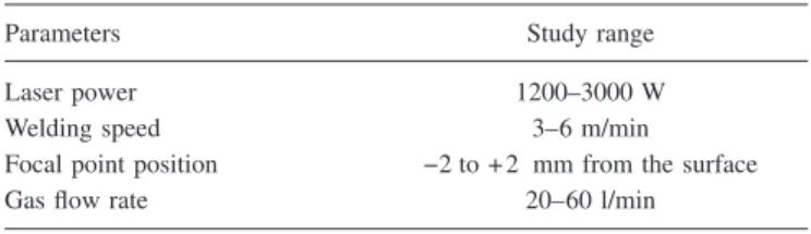
To optimize the laser welding process of the AM60 al-loy, the effect of welding parameters on weld quality is in-vestigated. Four parameters are chosen for this study: the beam power 共P兲, the welding speed 共S兲, the focal point po-sition 共FP兲 and the helium flow 共HF兲. Table II gives the welding parameters range.
After welding, weld beads are observed. First, visual controls are carried out to control full penetration depth weld and to detect not accepted weld with axial fracture. Then, using a digital camera, transverse macrographs are made to detect defects such as porosities and undercut weld. Finally,
weld widths are measured using Image and Measurement software in order to analyze the parameters effects on weld dimension.
Then, microstructures of the different zones of the weld, obtained by optimized parameters, are analyzed using a high magnification zoom microscope. Microstructure samples are mounted by resin ground and polished using 180 to 1200 grit abrasive SiC papers. Immediately after the last grinding step, the samples are washed with water, rinsed with methanol, and dried. A fine polishing is conducted using 0.5 m oil based diamond compounds. Samples are subsequently etched with acetic glycol etchant共60 ml ethylene glycol, 20 ml ace-tic acid, 19 ml water, 1 ml HNO3兲.13
Microhardness of as-received material and weld zones are also studied. The Vickers hardness is measured by a Leitz RZD-DO microdurometer. The measurements are done un-der 1.96 N loads during 15 s.
III. RESULTS AND DISCUSSION A. Welding process window
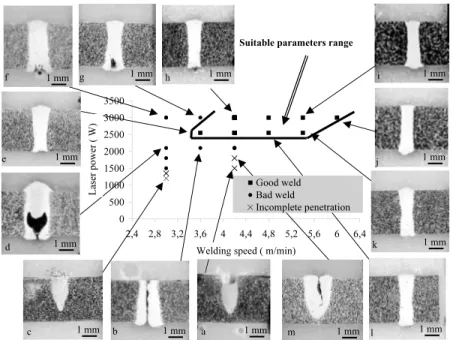
In order to determine laser beam welding parameters, laser power and welding speed are first varied. Obtained welds bead are analyzed and their widths are measured.
Beads top appearances are examined and welds are classified to be:
共i兲 Bad weld characterized by instable melting bath关Fig.
3共a兲兴 or undercut bead 关Fig.3共b兲兴.
共ii兲 Accepted weld characterized by full depth penetration weld with good quality solidification fronts 关Fig.
3共c兲兴.
Figure4shows welding speed and laser power effect on weld quality observed on transverse cross section. We can
FIG. 2. Welding fixture with clamped AM60 magnesium alloy samples. TABLE I. Chemical composition of AM60 magnesium alloy共HONSEL兲.
% Mg % Al % Mn % Zn
Balance 6.2 0.48 0.12
FIG. 1. Laser welding system.
TABLE II. Welding experimental condition of AM60 magnesium alloy.
Parameters Study range Laser power 1200–3000 W Welding speed 3–6 m/min Focal point position −2 to + 2 mm from the surface Gas flow rate 20–60 l/min
note that for laser welding and welding speed, respectively, over 2500 W and 3.6 m/min 关Fig. 4共e兲兴, a suitable laser
power-welding speed range is determined. In this case ob-tained beads are full depth penetration and no microscopic defects are detected. High quality solidification fronts are also observed.
However, bad laser welds quality is obtained at low pa-rameters values. For same papa-rameters, axial cracks 关Fig.
4共b兲兴 are detected. For others, shrink cavity are observed like those illustrated by Figs. 4共d兲 and 4共g兲. Incomplete depth weld penetration is also obtained for some P-S parameters like the example of weld obtained by 1200 W–3 m/min关Fig.
3共a兲兴 and 1500 W–4.2 m/min 关Fig.3共c兲兴. In this case power density, produced by the focused beam at the laser-matter interaction surface, is insufficient to melt from top to bottom the metal in 3 mm thickness sheets.
Then, at fixed welding speed, the laser power is varied. Analyzing cross section macrograph of welds realized with 1500关Fig.4共a兲兴, 1800 关Fig.4共m兲兴, and 3000 W 关Fig.4共h兲兴, it can be noted that the increase of laser power raises the melt-ing zone penetration depth.
Finally, for laser powers from the suitable P-S range, the molten zone dimension of welds obtained with different welding speed is measured. Welding bead width evolutions according process speed are presented in Fig.5. The increase of welding speed decreases welding bead width. This is due to the increase of linear energy 共E兲 defined by E= P/S. In fact, when welding speed raises thermal energy produced during laser-matter interaction diminishes owing the forma-tion of a smaller fusion zone.
B. Shielding gas flow effect
For parameters chosen on the suitable P-S range, we study the influence of helium flow rate on weld quality. Realizing welds with 3000 W laser power at 4.2 m/min, the helium flow rate is varied and obtained weld are analyzed.
Macrostructures, presented by Fig. 6, show top aspect and transverse cross section of welds obtained with 20, 40, and 60 l/min helium flow. It can be noted that due to a weak shielding gas flow, an axial crack is caused after cooling. Whereas the increase of the gas flow rate makes abundant plasma and decreases the weld width. In fact when the protection gas flow is important, laser power is absorbed by plasma. So the power density is reduced and bead width increases.
FIG. 3. Welding bead appearances for different process parameters.
e f d b k h g l i j c
Suitable parameters range
m a 1 mm 1 mm 1 mm 1 mm 1 mm 1 mm 1 mm 1 mm 1 mm 1 mm 1 mm 1 mm 1 mm
FIG. 4. Suitable laser beam power and welding speed range.
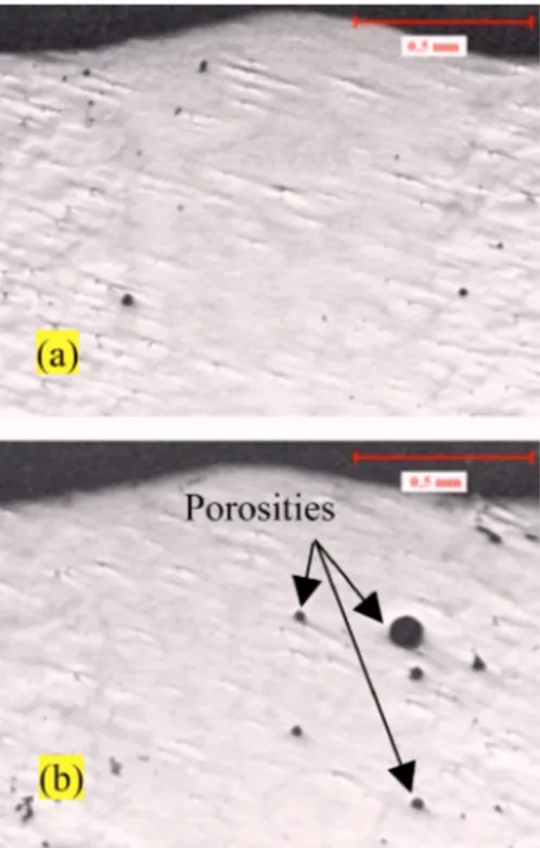
Another problem detected with high helium flow rate is the porosity diameters growth. Microscopic observations, presented by Fig. 7, show an increase in the size and the number of porosities at high helium flow rate. In this case, during welding, blowholes are captured inside molten zone owing the formation of porosities after rapid solidification. For laser beam welding of AM60 magnesium alloys, a suitable protection gas flow rate must be used. A 40 l/min helium flow rate is used to perform CO2laser beam welded assembly.
C. Focal point position effect
The focal point position effect is also investigated. Laser beam power, welding speed and helium flow rate are fixed at, respectively, 3000 W, 4.2 m/min, and 40 l/min. Focal point position from sample top surface is ranged from⫺1 to +2.
Figure 8 gives top surface appearance and transverse cross section of performed welds for different focal point positions. Beads examinations show that focal position has no effect on the weld quality. However, the weld profile is affected by the variation of the focal position. Welding bead width evolutions according focal position are presented by Fig.9. It can be noted that laser beam defocusing increases slightly weld bead width. This is due to the increase of laser power density 共W/cm2兲 that depends on the matter-laser
beam interaction surface range.
Pastor et al. have investigated laser beam defocusing influence on weld quality. They concluded that beam defocusing does not change weld width significantly. In addition, porosity formation is minor in thin welded sheets,
FIG. 6. Shielding gas flow effect on weld quality:共a兲 top weld appearance; 共b兲 transverse cross section macrographs.
FIG. 7. Porosities formation: P = 3000 W, S = 4.2 m/min, FP=0 and 共a兲 HF= 40 l/min, 共b兲 HF=60 l/min.
FIG. 8. Focal point position effect on weld quality:共a兲 top weld appearance; 共b兲 transverse cross section macrographs. P=3000 W, S=4.2 m/min and HF= 40 l/min.
than in thick ones and it is independent of focal point position.11 For next investigation of the AM60 laser beam welding, the focal point will be placed on the top surface of samples.
D. Microstructure investigation
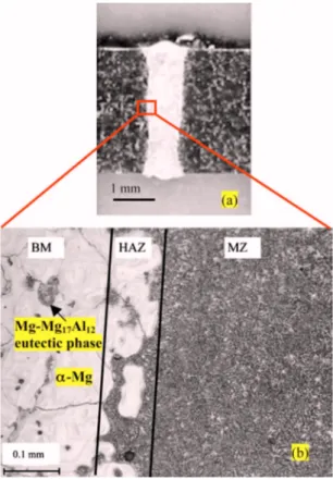
For metallurgical investigation, a weld bead is realized with optimized process parameters: laser power= 3 kW, welding speed= 4.2 m/min, helium flow rate=40 l/min and focal point at the surface of the sample. Figure 10displays metallurgical analysis results.
Weld macrographic observation, displayed by Fig.10共a兲, proves that, after CO2 laser welding of 3 mm thickness
AM60 sample, a uniform bead width is formed. Two zones with different microstructure are detected: the base metal 共BM兲 and the fusion zone 共FZ兲. Microscopically, a third zone is observed that is a transient area between MB and FZ, identified to be a heat affected zone共HAZ兲 关Fig.10共b兲兴.
The base metal is composed of coarse equiaxed ␣-Mg phase with Mg– Mg17Al12 eutectic phase located on grain
boundary. However, after solidification molten fusion is characterized by a dendritic microstructure. Liu et al. had observed this structure with high solidification rate of as-cast magnesium alloys melded by laser radiation.14 For chosen process parameters, the width of the obtained bead is about 900 m.
Due to high thermal heat conductivity of magnesium, it was observed that the detected heat affected zone共HAZ兲 is very small, with about 90 m in thickness. We can note
that, for the AM60 magnesium alloy, the only microstructure change in this zone is the liquefaction of the grain boundary bordering the molten region.
E. Hardness investigation
Vickers microhardness profiles are carried out for welded samples obtained with optimized process parameters: laser power= 3 kW, welding speed= 4.2 m/min, helium flow rate= 40 l/min and focal point at the surface of the sample. Measurements are made on the middle of the bead. Figure11 shows microhardness evolutions according to the distance from weld centerline. It can be observed that microhardness values increase on the fusion zone. In fact, the average hardness of base metal is about 58 HV. On fusion zone, the microhardness increases and is about 68 HV. Similar evolutions have been determined by microhardness measurement after CO2 and YAG laser
welding of AM60 and other die-cast magnesium-based alloys.10–12,15 For instance, Pastor et al. have investigated microhardness on Nd:YAG laser welded AM60 die-cast sheets. They have observed an increase of hardness on fusion zone. In fact, according them, hardness is about 63 HV in FZ and 53 HV in BM.11This hardness increase can be attributed to the refining of grains in fusion zone.10,12
IV. CONCLUSIONS
In this work, an experimental study is developed in order to investigate laser beam weldability of a die-cast magne-sium alloy. Process parameters effect on weld quality and metallurgical and mechanical welding consequences are dis-cussed. According to experimental results, the following main conclusions can be made:
共i兲 AM60 magnesium-based alloy can be successfully welded with a focused CO2laser beam.
共ii兲 Laser power and welding speed are the most impor-tant process parameters. They have an effect on weld appearance and quality, penetration depth and bead width. A power-rate process window is determinate for the assembly of 3 mm plate sheet.
共iii兲 Helium flow rate has an important impact on weld quality and bead width; a suitable flow must be used to obtain a good weld.
FIG. 10. Process conditions: P = 3 kW, S = 4.2 m/min, HF=40 l/min, FP = 0 mm.共a兲 Weld macrograph seam. 共b兲 Weld optical microstructure.
FIG. 11. Microhardness profile: P = 3000 W, S = 4.2 m/min, HF
共iv兲 Focal point position variation does not affect weld quality but changes bead profile.
共v兲 Microstructure changes after LBW are detected: den-dritic microstructure is observed in molten zone and a reduced size heat affected zone is displayed.
共vi兲 Hardness increases after laser welding of AM60 mag-nesium alloy.
ACKNOWLEDGMENTS
The authors are grateful to FONDERIE MESSIER 共HONSEL group兲 that provided the as-cast magnesium alloy workpieces. The authors would like also to acknowledge the technical support of Dr. Moraru of the LSIS Laboratory-Arts et Métiers ParisTech-Aix En Provence-France.
1B. L. Mordike and T. Ebert, “Magnesium: Properties-applications—
potential,”Mater. Sci. Eng., A 302, 37–45共2001兲.
2X. Cao, M. Jahazi, J. P. Immarigeon, and W. Wallace, “A review of laser
welding technicques for magnesium Alloys,”J. Mater. Process. Technol. 171, 188–204共2006兲.
3H. Haferkamp, M. Goede, A. Bormann, and P. Cordini, in “Laser beam
welding of magnesium alloys—new possibilities using filler wire and arc welding,” Proceedings of LANE 2001, edited by M. Geiger and A. Otto 共Meisenbach GmbH, Bamberg, 2001兲, pp. 333–338.
4L. Commin, M. Dumont, J. E. Masse, and L. Barrallier, “Friction stir
welding of AZ31 magnesium alloy rolled sheets: Influence of processing parameters,”Acta Mater. 57, 326–334共2009兲.
5X. Cao and M. Jahazi, “Effect of welding speed on the quality of friction
stir welded butt joints of a magnesium alloy,” Mater. Des. 30, 2033–2042 共2009兲.
6E. Mult, H. Haferkamp, M. Niemeyer, U. Dilthey, and G. Trager, “Laser
and electron beam welding of magnesium materials,” Weld. Cutt. 52, 178–180共2000兲.
7M. Dhahri, J. E. Masse, J. F. Mathieu, G. Barreau, and M. Autric, “Laser
welding of AZ91 and WE43 magnesium alloys for automotive and aero-space industries,”Adv. Eng. Mater. 3, 504–507共2001兲.
8M. Dhahri, J. E. Masse, J. F. Mathieu, G. Barreau, and M. Autric, “CO 2
laser welding of magnesium alloys,”Proc. SPIE 3888, 725–732共2000兲.
9A. Kouadri and L. Barrallier, “Texture characterisation of hexagonal
met-als: Magnesium AZ91 alloy, welded by laser processing,”Mater. Sci. Eng., A 429, 11–17共2006兲.
10A. Weisheit, R. Galun, and B. L. Mordike, “CO
2laser beam welding of
magnesium-based alloys,” Weld. Res. 74, 149–154共1998兲.
11M. Pastor, H. Zhao, and T. DebRoy, “Continuous wave-Nd:yttrium–
aluminium–garnet laser welding of AM60B magnesium alloys,” J. Laser Appl. 12, 91–100共2000兲.
12Y. Quan, Z. Chen, Z. Yu, X. Gong, and M. Li, “Characteristics of laser
welded wrought Mg–Al–Mn alloy,” Mater. Charact. 59, 1799–1804
共2008兲.
13F. Vander Voort, W. Ahmed, G. Blann, P. Didier, D. Fisher, S. Holt, J.
Klansky, and G. Lucas, The Science Behind Materials Preparation—A guide to materials preparation and analysis, BUEHLER®SUM-MET™, 2007.
14S. Y. Liu, J. D. Hu, Y. Yang, Z. X. Guo, and H. Y. Wang, “Microstructure
analysis of magnesium alloy melted by laser irradiation,”Appl. Surf. Sci. 252, 1723–1731共2005兲.
15H. Y. Wang and Z. J. Li, “Investigation of laser beam welding process of