HAL Id: hal-00538609
https://hal.archives-ouvertes.fr/hal-00538609
Submitted on 22 Nov 2010
HAL is a multi-disciplinary open access
archive for the deposit and dissemination of
sci-entific research documents, whether they are
pub-lished or not. The documents may come from
teaching and research institutions in France or
abroad, or from public or private research centers.
L’archive ouverte pluridisciplinaire HAL, est
destinée au dépôt et à la diffusion de documents
scientifiques de niveau recherche, publiés ou non,
émanant des établissements d’enseignement et de
recherche français ou étrangers, des laboratoires
publics ou privés.
Towards Gb/s turbo decoding of product code onto an
FPGA device
Camille Leroux, Christophe Jego, Patrick Adde, Michel Jezequel
To cite this version:
Camille Leroux, Christophe Jego, Patrick Adde, Michel Jezequel. Towards Gb/s turbo decoding of
product code onto an FPGA device. Circuits and Systems, 2007. ISCAS 2007. IEEE International
Symposium on, May 2007, New Orleans, United States. pp.909 -912, �10.1109/ISCAS.2007.378073�.
�hal-00538609�
Toward Gb/s turbo decoding of product code onto an
FPGA device.
Camille LEROUX, Christophe JEGO, Patrick ADDE and Michel JEZEQUEL
GET/ENST Bretagne, CNRS TAMCIC UMR 2872, Brest, France firstname.lastname@enst-bretagne.fr
Abstract—This paper presents the implementation, on an
FPGA device of an ultra high rate block turbo code decoder. First, a complexity analysis of the elementary decoder leads to a low complexity decoder architecture (area divided by 2) for a negligible performance degradation. The resulting turbo decoder is implemented on a Xilinx Virtex II-Pro FPGA in a communication experimental setup. Based on an innovative architecture which enables the memory blocks between all half-iterations to be removed and clocked at only 37.5 MHz the turbo decoder processes input data at 600Mb/s. The component code is an extended Bose, Ray-Chaudhuri, Hocquenghem (eBCH(16,11)) code. Ultra high-speed block turbo decoder architectures meet the demand for even higher data rates and open up new opportunities for the next generations of communication systems such as fiber optic transmissions.
I. INTRODUCTION
In telecommunications, forward error correction (FEC) is asystemoferror control thatimprovesdigital communication quality. A recent development in error correction is turbo coding.Block turbo codes (BTC) are an alternative solution to convolutional turbo codes (CTC) introduced in 1993 by C.Berrou [1]. BTC were proposed by R. Pyndiah [2] in 1994. The coding scheme uses a serial concatenation of systematic linear block codes (product codes introduced by P. Elias [3]) and the decoding is carried out using soft input-soft output (SISO) elementary decoders. Recently, BTC have been included in the specifications of the Wireless Metropolitan Area Networks (IEEE 802.16) standard to increase transmission rates and/or to guarantee the Quality of Service (QoS). Some processes like optical transmission or data storage require ultra high speed above 10 Gb/s data coding and decoding. The first codes used in optical transmission were the well-known Reed-Solomon codes [4] which allow respectable throughput for a Net Coding Gain (NGC) up to 6dB. In such contexts, BTC are an attractive solution since product codes structure present a high parallelism rate and a theoretical NCG of 10dB [5][6]. However, FEC decoders achieving multi-gigabit throughputs require new massively parallel architecture with reduced complexity.
In BTC, the iterative decoding algorithm of a matrix (product code) involves performing the successive decoding of all rows and all columns (two half-iterations). To increase thedata rate, it is possible to perform all the rows (columns) in parallel during a half-iteration. However in classical approaches [7], a reconstruction of the data is necessary between two successive half-iterations. This requires a large
amount of memory (up to 75% of the design) and limits the implementation possibilities. In [8], an innovative architecture that enables the memory blocks between each half-iteration to be removed has been proposed. In such an architecture, the remaining complexity is in the decoding processors: the number of required SISO decoders is DECn =
2×it×n, where it and n are the number of decoding iterations
and the code size respectively. Therefore, implementing a full parallel BTC decoderrequiresto decrease the complexity of the elementary SISO decoder architecture.
This paper is organized as follows. Section II recalls the basic principles of decoding for product codes: their construction and the turbo decoding process. In section III, we propose a complexity and performance analysis of the elementary decoder which allows a rapid and efficient estimation of the decoder complexity. Finally, in section IV, an implementation of the resulting turbo decoder onto a FPGA target is presented.
II. BTC CODING AND DECODING PRINCIPLES
In this section, the concept of product codes, their construction and the principle of the decoding algorithm are presented.
A. Construction of product codes
The concept of product codes is a simple and efficient method to construct powerful codes with a large minimum Hamming distance δ using conventional linear block codes.
Let us consider two identical systematic linear block codes C
having parameters (n,k), where n andk stand for code length
and number of information symbols respectively. The product code P=C×C is obtained by placing k2 information bits in a matrix of k rows and k columns, coding the k rows and k columns using code C. It is shown that all n rows are codewords of C exactly as all n columns. Furthermore, the parameters of the resulting product code P are given by
np=n2, kp=k2 and the code rate Rp is given by Rp=R2. Thus, it
is possible to construct powerful product codes using linear block codes. As a general rule, the more powerful a code, the more difficult the decoding process.
B. SISO decoding of product codes
Product code decoding involves sequentially decoding rows and columns using SISO decoders. Repeating this soft decoding over several iterations enables a decrease of the Bit Error Rate (BER). It is known as the block turbo decoding process. Each decoder has to compute soft information
previous half-iteration computed information [R’]k. A SISO
decoder of an eBCH code based on the Chase-Pyndiah algorithm [2][9] is concisely summarized below:
1- Search for the Lr least reliable binary bits and compute the syndrome S0 of [R’]k,
2- Generate Tv test vectors obtained by inverting some of the Lrleast reliable binary symbols,
3- Binary decoding of each test vector using the syndrome computation,
4- For each test vector, compute the square Euclidian distance (metric) Mi(i=0,…,Tvn-1) between [R’]k and
the considered test vector.
5- Select the Decided Word (DW) having the minimal distance with [R’]k and choose Cw concurrent words
having the closest distance with [R’]k.
6- Compute reliability [F]k for each symbol of the DW,
7- Compute extrinsic information [W]k=[F]k-[R’]k for
each symbol of the DW.
8- Add extrinsic information (multiplied by αk) to the
channel received word, [R’]k+1=[R]k+αk[W]k
An αk coefficient allows us to damp decoding decisions
during the first iterations. It should be noted that decoding parameters Lr, Tv, and Cw has a notable effect on
performance.
III. COMPLEXITY AND PERFORMANCE ANALYSIS FOR eBCH SISO DECODERS
Syntheses for the complexity estimations were performed using the Synopsys tool with an STMicrolectronics 0.09 μm CMOS process target. Elementary decoders are clocked at
f=500MHz. BER performance was simulated using C-ANSI
models of a turbo decoder for the product codes eBCH(16,11)² and eBCH(32,26)² after 6 iterations.
A. Complexity analysis of BCH SISO decoders
All the soft information within the decoder is quantized and processed with Q bits (1 sign bit and Q-1 reliability bits). The SISO decoder architecture is structured in three pipelined stages identified as reception, processing and
emission units. Each stage processes n symbols in n clock
periods. The resulting latency is then equal to 2n clock periods. The reception unit computes the syndrome S0 and
the Lr least reliable bits of the word received [R’]k. The
processing unit computes the syndrome of the Tv test vectors
and their metric values. Finally, the emission unit calculates new reliabilities from the metrics of the decided word and the Cw concurrent words. Extrinsic information [W]k and
soft output [R’]k+1 are also processed during the same clock
period. A new Q-bits symbol is then transmitted at each clock period. The decoding process needs to access the [R]k
and [R’]k values during the three decoding phases. For this
reason, these words are implemented in Random Access Memories (RAM) of size Q*n.
The proposed SISO decoder is composed of twelve processing parts. Running conventional decoder designs through logic synthesis showed that only four parts were critical in terms of logical gate complexity (75% of the area). As a result, our study is focused on these parts. One of these parts is the alpha multiplication unit. In classical architectures, it is implemented as a conversion table. The
input can be multiplied by 0.55 < αk < 0.75, the value
depending on the current iteration. Keeping αk = 0.5 for each
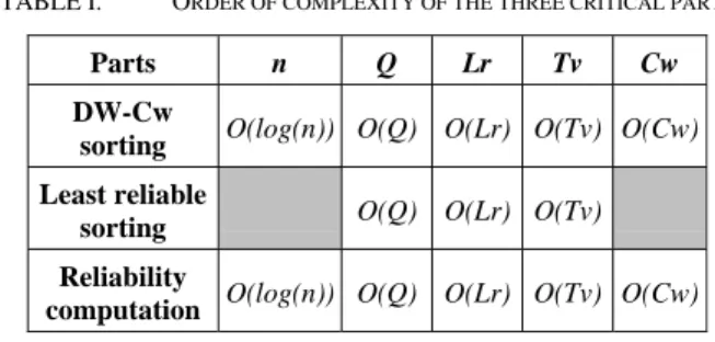
iteration enables the unit to be removed since the multiplication becomes a simple bit shifting. Therefore, the elementary decoder area is decreased by 8%. The induced loss of performance Δα is very low (0<Δα<0.1 dB). Consequently, the complexity analysis will now be focused on the three remaining parts. By analyzing the architecture of these critical parts, five parameters appear to directly affect their complexities. Table 1 sums up the order of complexity of the three critical parts that depends on the parameters introduced in section II. B.
TABLE I. ORDER OF COMPLEXITY OF THE THREE CRITICAL PARTS
Parts n Q Lr Tv Cw
DW-Cw
sorting O(log(n)) O(Q) O(Lr) O(Tv) O(Cw) Least reliable
sorting O(Q) O(Lr) O(Tv) Reliability
computation O(log(n)) O(Q) O(Lr) O(Tv) O(Cw)
Decoding parameters Lr,Tv, Cw, as well as the code size n and the number of quantization bits Q has a direct impact
on the decoder complexity (area or number of logical gates). Considering a code size n, let us define a set pi of decoding
parameters:
pi = { Qi, Cwi , Tvi , Lri}. (1)
Varying pi, directly affects both the hardware complexity and
the decoding algorithm performance. Increasing these parameter values improves performance while the complexity increases. The purpose of our analysis is to be able to compute easily the complexity of a SISO decoder for any set of parameters pi with reasonable accuracy.
Considering a code size n, the most favorable configuration is:
p0={Cw0=3,Q0=5,Tv0=16,Lr0=5}. (2)
Actually, increasing p0 parameters values would increase
complexity without significantly improve performances. For this reason, this configuration is the reference for our decoder architecture complexity. Synthesis showed that, in this case, the four critical parts represent 75% of the decoder area whatever the code size n. In addition, assuming that the remaining 25% of the decoder is almost not affected by the variation of a set pi (as verified during syntheses), it can be
demonstrated that the SISO decoder complexity Cpi(n) can
be expressed as:
Cpi(n)= 1/3 (C’p0(n)) + C’pi(n), (3)
whereC’pi(n) is the cumulated complexity of the four critical
parts in terms of logical gates for a parameter set pi.
Synthesizing generic descriptions of the critical parts and carrying out a multiple linear regression analysis led to an expression of C’pi(n) only depending on the decoding
complexity C’pi(n) of the four critical parts in terms of
logical gates for a parameter set pi.
C’pi(n) = 462(Cwi-1) + 261(log(n)-4) + 183(Qi-4) +
55(Tvi-4) + 46(Lri-2) + 1019 . (4)
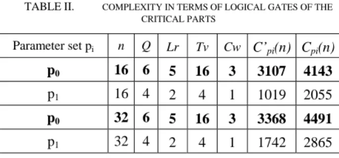
The model’s accuracy was measured a posteriori. The maximum and average errors (between model and synthesis results) are 8% and 2.5% respectively. Table II gives four examples of estimated complexity for code size n=16and32.
TABLE II. COMPLEXITY IN TERMS OF LOGICAL GATES OF THE CRITICAL PARTS Parameter set pi n Q Lr Tv Cw C’pi(n) Cpi(n) p0 16 6 5 16 3 3107 4143 p1 16 4 2 4 1 1019 2055 p0 32 6 5 16 3 3368 4491 p1 32 4 2 4 1 1742 2865
Using this model immediately gives the complexity of an eBCH SISO decoder for any set of decoding parameters. Therefore, taking into account the implementation and performance constraints, it becomes very straightforward to select a code size n and a decoding parameter set pi.
B. Selection of a parameter set and a code size
Simulations showed that for a small size of product code (eBCH(32,26)² and eBCH(16,11)²), the performance degradation associated with the particular set p1 ={Cw=1,
Q=4, Tv=4, Lr=2} was only about 0.3 dB at BER=10-4. Furthermore, for n=16, simulations showed that the loss of performance became negligible for SNR > 4dB. It can be seen that decoding parameters in p1 have low values. The
complexity of the SISO decoder is then highly reduced for reasonable performance loss. Using (3) and (4), Cp1(16) =
2055 logical gates and Cp1(32) = 2865 logical gates were
obtained. Compared with the decoder complexity reference
Cp0(16) and Cp0(32), gains of 50% and 36% were achieved
respectively.
A block turbo decoder designed according to the complexity analysis results has to be integrated. Currently, a typical hardware design approach is to use an FPGA development board to first prototype the turbo decoder design and its experimental setup. The low cost Virtex II-Pro XUP [10] development system from Digilent was selected for our experimentation. These boards contains a Xilinx Virtex II-Pro XC2VP30 FPGA device with 13696 slices. Preliminary syntheses show that only a half-iteration of the eBCH(32,26)² block turbo decoder would fit onto the Virtex II-Pro XC2VP30 device. Indeed, some elements of the experimental setup have to fit onto the same FPGA device as the block turbo decoder. In the case of BCH(16,11)², up to 3 half-iterations (48 SISO decoders) can be implemented on the same device. For this reason, the BCH(16,11)² was finally chosen for our experimentation. The parameter set
p1={Cw=1, Q=4, Tv=4, Lr=2} was selected for each
elementary decoder.
IV. IMPLEMENTATION OF A BLOCK TURBO DECODER IN AN ULTRA HIGH RATE COMMUNICATION SETUP
A. Experimental setup
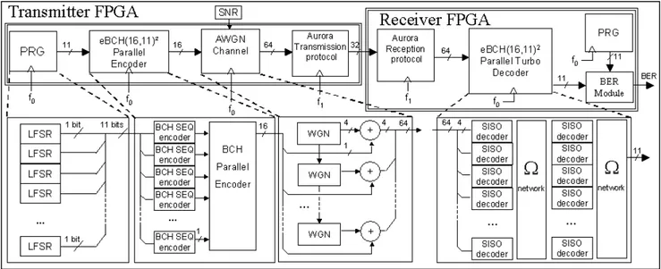
The experimental setup is composed of two identical development boards XUP linked with a Serial ATA communication bus. BER measurement facilities are implemented in order to rapidly verify the decoding performance. Each board contains a Xilinx XC2VP30 device that can transmit data at a 2.4 Gbits/s rate. Indeed, encoded noisy data are sent from the transmitter FPGA to the receiver FPGA using the high speed Xilinx Aurora protocol. Each board has its own digital clock management system operating at 50MHz. Synchronization between the two boards is carried out by Aurora protocol control signals. The Aurora protocol is clocked at f1=75MHz and the rest of the
setup is clocked at f0=37.5MHz. Figure 1 shows the different
components of the communication setup implemented onto the FPGA.
1) The components implemented on the transmitter FPGA device
A Pseudo Random Generator (PRG) sends out eleven pseudo random data streams at each clock period (f0). It is
composed of eleven different LFSR. An eBCH(16,11)2 encoder processes the eleven data streams in parallel. This innovative architecture avoid the use of memory between row and column encoding [8]. Classical sequential encoders are cascaded with a parallel encoder. 256 data (equivalent to a matrix 16×16) are generated in 16 clock periods (f0). The
noise generator models 16 uncorrelated White Gaussian Noise (WGN) samples and adds them to the previously encoded data [11]. Each output sample is a 4 bit vector resulting in 64 bits to be sent in 1 clock period (f0). The
Signal to Noise Ratio (SNR) is controllable via on-board switches 0<SNR<15.75dB with a pitch of 0.25dB. The Aurora protocol emission module handles a set of control signals. It receives 64 data in 2 clock cycles and sends 32 data every clock cycle (f1). The output rate is then 2.4Gb/s.
2) The components implemented on the receiver FPGA device
The Aurora protocol reception module receives data at 2.4 Gbits/s and sends out 64 bits every two clock cycles (f1).
The turbo decoder is composed of 32 SISO (16 SISO decoders per half-iteration) and two omega networks used to route data between half-iterations. More information about the decoder architecture and the omega network can be found in [8]. Data arrive at 2.4Gb/s while the working frequency is only 37.5 MHz. The same PRG is also implemented in the receiver. It generates the exact same data as in the transmitter in order to compare data before and after decoding. A BER block is finally used to measure the error rate comparing data from the PRG and the decoder output. It guarantees a minimum of 1000 errors before outputting the BER value. This value is then displayed on an LCD module. The minimum reliable BER value is 10-9.
B. Toward very high rate implementation
The purpose of this first implementation is to show that a block turbo decoder can effectively work without memories
between half-iterations at high throughput. Clocked at only 37.5MHz, the turbo decoder processes input data at 600Mb/s. This frequency is limited by the communication protocol. The turbo decoder can actually perform up to 70MHz on this target, which corresponds to 1.12 Gb/s. Using an FPGA device optimized for high-performance logic
would lead to even higher frequency. Regarding the output rate, it is defined as:
Dout = P f R . (5)
P is the parallelism rate (max(P)=n), f the decoder
frequency and R the code rate.
Figure 1. Multi-gigabit experimental setup
In our case, P=16, f=f0=37.5MHz and R=0.473, the
resulting throughput is then 284Mb/s. Several solutions exist to increase the throughput, the more straightforward is to use a larger code (in order to increase P) with a larger rate R. For instance, assuming we are using an eBCH(32,26)2 at frequency f0=70MHz, the input and output data rates become
2.24Gb/s and 1.48Gb/s respectively. In our architecture, SISO decoders process data sequentially. Designing SISO decoders which decode several data in one clock period, as in [12], would again improve throughput and with a limited complexity overhead. Moreover, enhancing our study to non binary component codes like RS codes [13] can increase data rate even more. The turbo decoder was synthesized and implemented on a Virtex II Pro FPGA using Xilinx ISE 7.1i tools. The decoder occupied 7300 slices. So far, one iteration (32 SISO decoders and 2 omega networks) has been fully implemented. The available target (xc2vp30) was insufficient to implement several iterations. Duplicating the decoders simply requires a larger FPGA target. Implementing a 6-iterations full-parallel turbo decoder represents 43800 FPGA slices with a maximum throughput. Such a design can for instance, fit onto a Xilinx Virtex 4.
V. CONCLUSION
This article shows how we implemented a memory free, high-throughput, full-parallel, block turbo decoder on a FPGA target. In such parallel architectures, it is necessary to use low complexity SISO decoders. We first proposed a complexity analysis for the eBCH(16,11) SISO decoder. The complexity expression gives a rapid estimation of the SISO area, for a fixed set of decoding parameters. Then, depending on the required level of performances, it becomes easy to decide on a
set of parameters to implement. This analysis led to a low complexity SISO decoder (-50%) to be duplicated in the parallel turbo decoder. Next, we describe the experimental setup designed to test the turbo decoder. Using a more efficient communication protocol the turbo decoder can process input data at 1.2Gb/s. Using a larger code, with a higher rate and parallel SISO decoders, would again, increase the data rate. Moreover non binary codes like RS codes enable even higher throughputs to be reached.
REFERENCES
[1] C. Berrou, A. Glavieux and P. Thitimajshima, “Near Shannon limit error-correcting coding and decoding : Turbo-codes (1),” IEEE Int. Conf. on Comm.ICC' 93, vol 2/3, May 1993, pp. 1064-1071.
[2] R. Pyndiah, “Near optimum decoding of product codes : Block Turbo Codes”, IEEE Trans. on Comm., vol 46, n° 8, August 1998, pp. 1003-1010.
[3] P. Elias, “Error-free coding”, IRE Trans. on Inf. Theory, vol. IT-4, pp. 29-37, Sept. 1954.
[4] K. Azadet, E.F. Haratsch, H. Kim, F. Saibi, J.H. Saunders, M. Shaffer, L. Song, Meng-Lin Yu, “Equalization and FEC techniques for optical transceivers”, Solid-State Circuits, IEEE Journal of Volume 37, Issue 3, March 2002, pp. 317-327.
[5] O. Ait Sab, O. V. Lemaire, “Block turbo code performances for long-haul DWDM optical transmission systems”, Optical Fiber Communication Conference,Volume 3, March 2000 pp. 280-282. [6] T. Mizuochi, “Recent Progress in Forward Error Correction for Optical
Communication Systems”, IEICE Transactions on Communications, Volume E88-B, Number 5, May 2005.
[7] S. Kerouedan, P. Adde, “Implementation of a Block Turbo Decoder on a Single Chip”, 2nd International Symposium on Turbo Codes & Related Topics, Brest, France, 2000. p. 243-246.
[8] C. Jego, P. Adde, C. Leroux, “Full-parallel architecture for turbo decoding of product codes”, Electronics Letters Volume 42, Issue 18, 31 August 2006 pp. 55 – 56.
[9] D. Chase, “A class of algorithms for decoding block codes with channel measurement information”, IEEE Trans. Inform. Theory, vol IT-18, Jan. 1972, pp 170-182
[10] .http://www.xilinx.com/univ/XUPV2P/Documentation/XUPV2P_User _Guide.pdf
[11] J.L Danger, A. Ghazel, E. Boutillon H. Laamari, “Efficient FPGA Implementation of Gaussian Noise Generator for Communication Channel Emulation” (ICECS'2K), Kaslik, Lebanon, Dec 2000. [12] J.Cuevas, P.Adde, S.Kerouedan, “Very powerful block turbo codes for
high data rates applications”, 3rd International Symposium On Turbo Codes & Related Topics, Brest, France, 1-5 septembre, 2003. p 251-254.
[13] E.Piriou, C. Jego, P. Adde, R. Le Bidan, M. Jezequel, “Efficient architecture for Reed Solomon block turbo code”, ISCAS 2006 : International Symposium on Circuits and Systems, Kos, Greece, May 21-24, 2006. p. 3682-3685.