HAL Id: hal-01774922
https://hal.archives-ouvertes.fr/hal-01774922
Submitted on 30 Jan 2020
HAL is a multi-disciplinary open access
archive for the deposit and dissemination of
sci-entific research documents, whether they are
pub-lished or not. The documents may come from
teaching and research institutions in France or
abroad, or from public or private research centers.
L’archive ouverte pluridisciplinaire HAL, est
destinée au dépôt et à la diffusion de documents
scientifiques de niveau recherche, publiés ou non,
émanant des établissements d’enseignement et de
recherche français ou étrangers, des laboratoires
publics ou privés.
Copyright
Sensor-Based Control
Sylvain Vandernotte, Abdelhamid Chriette, Adolfo Suarez Roos, Philippe
Martinet
To cite this version:
Sylvain Vandernotte, Abdelhamid Chriette, Adolfo Suarez Roos, Philippe Martinet. Performing
As-sembly Task Under Constraints Using 3D Sensor-Based Control. Intelligent Autonomous Systems,
2016, Padua, Italy. pp.1389-1399, �10.1007/978-3-319-08338-4�. �hal-01774922�
Performing Assembly Task Under Constraints
Using 3D Sensor-Based Control
Sylvain Vandernotte1, Abdelhamid Chriette2, Adolfo Suarez Roos3, and
Philippe Martinet2
1 IRT Jules Verne, Chemin du Cha↵aut, F-44340 Bougennais, France 2 IRCCyN, UMR CNRS 6597, 1 Rue de la Noe, F-44321 Nantes Cedex, France
3 Airbus Group Innovations, 13 Rue Pasteur, F-92152 Suresnes, France
Abstract. Basic robotic operations such as grasps of structure’s parts and their placement are mostly model-based and do not take into ac-count modelling error and geometry variations. As consequences, quality of the assembly cannot be trusted. In this paper, we propose to use 3D sensor and sensor-based control to improve the precision a positioning task. The interaction matrix is constructed upon assembly constraint definition. Those assembly constraints are taken into a task sequencing mechanism, with others robot-specific and environment tasks. The posi-tioning operation is tested with Gazebo simulator and ROS environment and demonstrate the e↵ectiveness of the approach.
1
Introduction
Assembly tasks become an active field of research in robotics community. Indus-trial companies already benefits of robots for highly repetitive and low accuracy tasks such as welding or palletization tasks, in order to improve their produc-tivity and reduce their functional costs. However, others are still difficult to automate. Non-controlled environment, low mobility and low perception capac-ities are the main obstacles for this. Car, planes and boats are all manufactured products that require significant e↵ort for their assembly. There are still a non-negligible amount of tasks in the production process where parts, structures and others components are installed by hand. This kind of operation would require a certain degree of dexterity and mobility of the hand, the wrist and the arm, but not only. An assembly task hides a lot of small intermediate steps in order to place the objects successfully. It goes from identifying its final location in a complex environment, to handle motion toward this pose without undesired contacts, passing through gathering the necessary documentation.
Previous works in assembly using robots mainly focused on planning robot’s motion and managing resources. In [12], the authors built a top-level construc-tion algorithm to manage a team of mobile robots to construct truss structures. Robots are specialized in two functions: assembling and delivering. The algo-rithm coordinates the assembly to maximizing parallelism across assembly robots and conforming to physical constraints of the structure. In a same way, [9] de-signed an algorithm that produces a sequence of assembly tasks while they take into account timing constraints and parts availability. [15] designed a planner
that generates an assembly sequence to construct a three-dimensional product from modular units. In [14] and [13], assembly tasks is defined based on pre-defined function blocks that describe elementary assembly function, in order to transform a previously generated assembly sequence into predefined robot’s mo-tion. These e↵orts are necessary but do not met industrial needs at this time. Most of industrial companies use large-scale CAD softwares which help them to manage resources and schedule the assembly.
Industrial needs are more about how to use robots in complex and non-controlled environment. All these previous approaches require a perfect knowl-edge of the environment to ensure the success of the assembly. Robot’s motion with respect to objects (structures, parts) are model-based, which means that they do not take into account part geometry and position variations. Visual servoing [5] and 3D sensor-based control techniques already prove their ability to perform robust control based on real world measured features. These tech-niques and new types of 3D sensors are mixed in a new way to perform assembly tasks by a manipulator robot. 2D features in visual servoing control have sev-eral drawbacks, such as not straight end-e↵ector cartesian trajectory or local minima, which disqualify them for assembly tasks. In contrary, 2D features as-sociated with depth information [2] showed similar performances to 3D features. Equivalently, [3] and [4] proposed to improve image-based visual servoing using 3D features in order to get straighter cartesian trajectory and enhanced conver-gence region. Finally, [10] prove that control based on 2D points features and depth is globally stable with any initial conditions.
All previous works related to assembly operations performed by robots as-sume that the world exactly corresponds to its model. Robotic operations are done considering netheir localization errors nor geometry variability of the part. Thanks to sensor-based control schemes, the idea is to significantly improve the absolute precision of the end e↵ector pose with respect to local reference features where the robot task definition relies on the assembly semantics. The main con-tribution of this paper is to define a task-formalism control framework that can mix assembly constraints (coincident plane, point-to-plane distances, etc.) and robot-specific constraints (joint limit, singularities, collisions, etc.). It focuses on the interaction matrix definition based on assembly constraints and its integra-tion in a task sequencing scheme. A precise approach of the final pose of the part is considered and simulated. The case is fixing a shelf on a wall, the simulation shows the robot bring the fixture very close to its final pose.
The paper is organized as follows: section 2 describes the scene, the task definition and its corresponding interaction matrix for one assembly constraint. The multi-tasks hierarchical control scheme is explained in section 3. Finally, simulation results are shown in section 4.
2
Relative positioning using assembly constraints
We want to demonstrate that the robot arm is able to perform a precise po-sitioning task using sensor-based control techniques and assembly constraints.
3
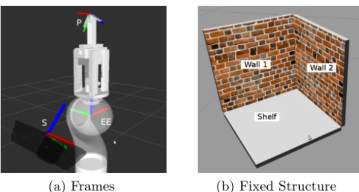
(a) Frames (b) Fixed Structure
Fig. 1: Frames disposition at end e↵ector of the KUKA LWR4+. Frames EE, S and P represent respectively the end e↵ector frame, the sensor frame and the part frame.
The experiment will lead to a positioning task of a part with respect to a struc-ture where the part is supposed to be assembled. It can be seen as an operation of placing a fixture to mount a simple shelf on a wall, considering that fixation can be completed by another robot or an operator. Only the positioning be-fore establishment of the contact is considered in this paper. The part is placed at predefined distance of the structure by using three plane-to-plane distance constraints.
The scene is composed of the robot next to the structure. The robot arm used in simulation is the KUKA LWR4+ with seven degrees of freedom (DOFs). The shelf is placed in a corner of a room at a certain height, so that the structure can be seen as a collection of three rigid orthogonal planes. The part is held thanks to a parallel-jaw gripper attached on the robot’s end e↵ector. It is assumed that the pose of the part with respect to the end e↵ector frame is known and rigid (the part can be considered light enough to avoid slippage when held). The final pose of the part is also reachable by the robot. Distances are measured from part to plane by a depth sensor attached to the end e↵ector link. Finally, we assume that the simulated environment is simple enough to avoid occlusion of measured features from the sensor. See figure 1 for illustrations.
Assembly constraints describe how parts – or a set of parts – are arranged to be fixed onto another one. Without a loss of generality, a constraint can be defined as a collection of two features of each sets (faces, edges, points, planes, etc.) and a local geometric description of their position between each other. Co-incident planes, for example, is a constraint that makes two planes of each set parallel with a distance along their normals equal to zero. It can be named also plane-to-plane distance. This type of constraints fix only 3 DOFs in space (1 translation and 2 orientations). We need three such constraints with orthogonal direction to set the whole pose of the part, as shown in figure 2a. Coincident 3D points in space fix the three translations but do not constraint orientation. The positioning task is done by using three plane-to-plane distance constraints to place our part really close to the structure before making contact. The distance
P dAM M A (a) P dAM1 M1 A1 dAM2 dAM3 A2 A3 M3 M2 (b)
Fig. 2: Illustration of plane-to-plane distance constraints.
is estimated from sensor stream. The sensor gives a point cloud as output, the cluster of points corresponding to the structure is extracted. Plane equations is then deduced. Related work can be found in [7] where they use of structured light and a camera to constraint the robot’s end e↵ector with respect to a plane. Here, 3D informations brings the possibility to simplify the task definition.
From the plane equation, the estimate of the distance between plane P = [ a b c d ]|and an arbitrary 3D point M = [ xM yM zM ]|is,
dAM = axMp+ byM + czM + d
a2+ b2+ c2 (1)
where A is the orthogonal projection of M onP. From this, the plane-to-plane distance constraint can be reformulated equivalently as three point-to-plane dis-tances, under conditions that all three points belong to the same plane, they are not aligned and all distances are equal.
In order to build the interaction matrix of the point-to-plane constraint, two 3D points L = [ xL yL zL ]| and M = [ xM yM zM ]| are considered such as
LM is collinear with n. The distance dLM is given as the sum of the distance
from L toP, and from M to P:
dLM= axLp+ byL+ czL+ d
a2+ b2+ c2 +
axM + byM + czM + d
p
a2+ b2+ c2 (2)
One can deduce the interaction matrix that maps the evolution of the distance ˙
dLM to the evolution of the both 3D points:
Ld= @dLM @L = @dLM @M = 1 p a2+ b2+ c2 ⇥ a b c⇤ (3) This interaction matrix holds for any couple of points that form a vector collinear with the plane normal. L is then remplaced by A. Since A belongs to the plane, equations (2) and (1) are equal, but the interaction matrix Ld still holds. The
interaction matrix can be completed to express ˙dLM in function of the sensor
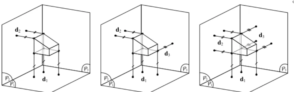
5 P2 P1 P3 d1 d2
(a) 5 distances: 5 DOFs con-strained P2 P1 P3 d1 d2 d3
(b) 6 distances: 6 DOFs con-strained P2 P1 P3 d1 d2 d3
(c) 9 distances: 6 DOFs con-strained, redundant
Fig. 3: Use of distances to place the part. (a) shows a positioning task with respect to two planes, (b) and (c) with respect to three planes. Since 5 DOFs are constrained byP1 andP2, there only need to consider only one distance to
complete the third sub-task. ˙
dAM = LdLAv (4)
where LA=⇥ I3[A]⇥⇤1 is the interaction matrix of the 3D point A.
Using this, the interaction matrix for a plane-to-plane constraint is the stack of three interaction matrices defined in equation (4).
˙d = 2 4 ˙ dA1M1 ˙ dA2M2 ˙ dA3M3 3 5 = 2 4LLddLLAA12 LdLA3 3 5 v (5)
Hereafter is given the complete 3⇥ 6 interaction matrix L for one plane-to-plane constraint: L = p 1 a2+ b2+ c2 2 4 aa bb c bzc bzA1A2 cycyA1A2 cxcxA2A1 azazA2A1 ayayA2A1 bxbxA1A2 a b c bzA3 cyA3 cxA3 azA3 ayA3 bxA3 3 5 (6) Special attention is needed about the task’s objective: it is defined along the normal direction of the plane, depending on how the plane is extracted from sensor data. If the direction in the task definition is the opposite of the extracted plane, the control law could diverge and the system behaviour would not be as expected. The next section shows how the constraints are put together.
3
Constraints-based control
3.1 Ensuring assembly constraints using sub-tasks
In a assembly operation, satisfying all constraints at same time could be difficult. Some of them could exert contradictory command on the same DOF. Or one have to be set before others to perform the assembly, which can be seen as an higher
1 [A]
priority upon the other constraints. At a human level, perform an assembly task looks more like following assembly constraint under a priority scheme decided after examining the two parts, rather than forcing the assembly under the risk of damaging it. Here, we want to follow the same kind of idea for our positioning task. As previously said, the task rely on three plane-to-plane constraints with orthogonal direction, so that the part’s pose is fully constrained. But on the other hand, one of these would fix 3 DOFs, making the task redundant. Conflicts are avoided by using only the necessary number of distances for each constraints, as shown in figure 3b. Moreover, a task sequencing scheme is used to apply each constraint following a priority order to the robot control.
Let us say that the three constraints have to be set following an arbitrary priority order, such that placing the part with respect to the shelf (plane P1),
is more important than the first wall (P2) and placing with respect to the first
wall is more important than the second (P3). By doing this, three sub-tasks are
defined, so that they can be taken into account using the redundancy formalism. 3.2 Considering one constraint
Let q be the vector of joint position of the robot, and ei the task function
associated to one constraint. The joint velocities ˙q are inputs for the robot control. The complete interaction matrix for one constraint is:
˙ei= Ldi sT
eeJe˙q (7)
where, Ldi is the interaction matrix defined at equation (5), sT
e the velocity
twist transformation matrix from the sensor frame to the end e↵ector frame and
eJ
e kinematic matrix of the robot. For the rest of the paper, the task jacobian
J is defined as the following:
Ji= Ldi sT
eeJe (8)
The controller aims to regulate the error ei to zero according to a reference
behaviour ˙e⇤i defined such that:
˙e⇤i = (di d⇤i) (9)
where diand d⇤i respectively stand for the measured distance and its objective.
The joint velocities deduced from ˙e⇤
i is given by the least square inverse of
(7):
˙q = J+i ˙e⇤i (10)
where J+i represent the Moore-Penrose pseudoinverse of Ji.
So far, the control law is not stable since the robot is not fully constrained. It is explained by the rank of Ji (m = 3) smaller than the number of DOF of
the robot (n = 6). The control law is continuous as long as the direction of the desired distance is not parallel the plane normal.
7
3.3 Taking into account all the constraints
As already said, the three constraints are considered following a priority order defined in section 3.1. Since the task jacobian is rank-deficient with respect to the number of DOF of the robot, a second criterion can be used in equation (10) using the redundancy formalism [8]:
˙q = J+˙e⇤+ Pzq˙2 (11)
where P is the projection operator onto the null space of the task jacobian J and zq˙2 an arbitrary vector which can be used to apply a second control referring to
an other sub-task. Thank to (11), motion defined in the secondary task could be performed without disturbing the first task, having a strict higher priority.
Let be e1, e2, e3 task functions associated respectively to the constraints
associated to the shelf, to the first wall and to the second wall, the equation (11) is generalized by using the efficient task sequencing scheme [11], ensuring the proper hierarchy between between all sub-tasks. For the first sub-task e1,
motion is deduced such as in (10).
˙q1= J+1 ˙e⇤1
P1= In J+1J1
(12) The following recursion is used for the two others:
˙qi= J+i ˙e⇤i (JiPi 1) ( ˙e⇤i Ji˙qi 1)
Pi= Pi 1 (JiPi 1)+(JiPi 1)
(13) for i = 2, 3. The joint velocities realizing all tasks is q3. Similarly as equation
(11), the product JiPi 1 is orthogonal to the task jacobian Jj of sub-task ej
having higher priority over ei, meaning that all sub-tasks are fully decoupled
from each others. In our case, considering all nine distances (figure 3c) together would yield to a redundant system. Here, by using the equation (13), unnecessary components of the second and third redundant sub-tasks would be removed by the action of the orthogonal projector.
4
Simulation Results
The aim of this paper is the precise positioning task before establishing the con-tact to complete the assembly. All simulations were made using Gazebo Simula-tor [6] and ROS environment [1]. The context of the experiment is the following: the robot grasps a part in a way that makes possible the assembly task with-out undesired collision between the robot and its environment. The pose of the structure is approximately known and the final pose of the part is defined with respect the structure frame. So that the part could not be placed precisely up the knowledge we have of the scene. However, the robot brings the part the closest to the desired pose as best as it can. Next, it will use the sensor-based control scheme presented in previous sections to ensure a precise pre-positioning oper-ation before making contact, relying on the plane-to-plane distance constraints.
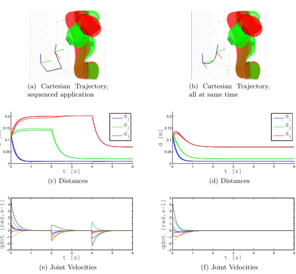
(a) Cartesian Trajectory, sequenced application
(b) Cartesian Trajectory, all at same time
0 1 2 3 4 5 6 0 0.05 0.1 0.15 0.2 t [s] d [m] d 1 d 2 d 3 (c) Distances 0 1 2 3 4 5 6 0 0.05 0.1 0.15 0.2 t [s] d [m] d 1 d 2 d 3 (d) Distances 0 1 2 3 4 5 6 −3 −2 −1 0 1 2 3 4 5 t [s] qdot [rad.s − 1]
(e) Joint Velocities
0 1 2 3 4 5 6 −3 −2 −1 0 1 2 3 4 5 t [s] qdot [rad.s − 1] (f) Joint Velocities
Fig. 4: Precise positioning with plane-to-plane constraints. Two experiments were conducted to check convergence of the control law.
First experiment is constructed to approach the worst case where the pose of the structure is badly calibrated, so that the translational error between reached uncertain desired pose and the real one is up to 10cm and its rotational error up to±10 . Distance objectives for each sub-task are respectively, in priority order, 1cm far from the shelf, 2cm from the first wall and 7cm from the second.
Figure 4a, 4c and 4e are obtained applying sub-tasks at di↵erent time step, respectively 0s, 2s and 4s. Sub-tasks e2 and e3 are activated by releasing the
distance error in program. All distances reaches their objective at the end of operation, which means that the control law converges. As seen in figure 4c, the application of e2 has no e↵ect on e1 and the application of e3 has no e↵ect on
9
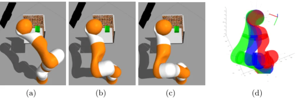
(a) (b) (c) (d)
Fig. 5: Auxiliary task : using redundancy to get away from the fixed structure straight line when all sub-tasks start together.
Second experiment shows that the positioning system is compatible with other auxiliary tasks such as collision avoidance. A fourth sub-task is set with the aim of keeping the robot away from the structure. This is done simply by applying a positive angular speed on one joint. The KUKA LWR4+ is a redun-dant robot, the previous experiment fixed only 6 DOFs while the robot has 7. It means that the 7thDOF was subject to external noise. By setting this 4th
sub-task, the all robot is now constrained. Motion during convergence is presented in figure 5. The task sequencing scheme allows the motion until it becomes incom-patible with the higher priority sub-tasks. It finally stabilizes in position shown in figure 5c. Superposition in figure 5d show that this motion brought by the last sub-task force to move all joints, but keep the precise positioning task in place.
5
Conclusion
In this paper, a sensor-based control approach has been described to complete assembly operations. As this operation is specified with assembly constraints, a sensor-based control task has been defined and built following these. Plane-to-plane has been primarily considered and 3D depth sensor used to get a measure of the plane equation. These informations allowed us to construct the interac-tion matrix to map the joint mointerac-tion to the measure evoluinterac-tion. We used also a task sequencing scheme to handle several constraints while respecting a priority order between them. Thanks to this, this robotic assembly task was compatible with other types of constraints. Simulation has been designed to validate the concept. However, sensor has been considered as a perfect sink, without taking into account noise and possible occlusions.
Future works will consider firstly the force control, allowing the contact es-tablishment between structure and object following the task function approach. Secondly, occlusion related problems will be tackled with the use of several re-dundant sensors and an improved management of task priorities between all sinks. Finally, the concept needs to be tested with noisy sensors to check if the improved precision objective is reached.
Acknowledgement
This paper describe works carried out in the framework of the ASIMOV project, funded by the Institut de Recherche Technologique Jules Verne, Bougennais, France.
References
1. Berger, E., Conley, K., Faust, J., Foote, T., Gerkey, B., Leibs, J., Quigley, M., Wheeler, R.: Robot Operating System (ROS). http://www.ros.org/wiki/ROS/ (2007), [Online; last access in 2014]
2. Cervera, E., Martinet, P.: Combining pixel and depth information in image-based visual servoing. In: Proceedings of the International Conference on Advanced Robotics. vol. 1, pp. 445–450 (1999)
3. Cervera, E., Berry, F., Martinet, P.: Is 3d useful in stereo visual control? In: Proceeedings of the IEEE International Conference on Robotics and Automation (ICRA). vol. 2, pp. 1630–1635 (2002)
4. Cervera, E., Del Pobil, A., Berry, F., Martinet, P.: Improving image-based visual servoing with three-dimensional features. The International Journal of Robotics Research. 22(10-11), 821–839 (2003)
5. Chaumette, F., Hutchinson, S.: Visual servo control: I. basic approaches. Robotics & Automation Magazine, IEEE. 13(4), 82–90 (2006)
6. Koenig, N., Su, J., Dolha, M., Howard, A.: Gazebo: Opensource multi robot sim-ulator. http://www.gazebosim.org/ (2002), [Online; last access in 2014]
7. Pages, J., Collewet, C., Chaumette, F., Salvi, J.: Plane-to-plane positioning from image-based visual servoing and structured light. In: Proceedings of the IEEE/RSJ International Conference on Intelligent Robots and Systems (IROS). vol. 1, pp. 1004–1009 (2004)
8. Samson, C., Espiau, B., Borgne, M.L.: Robot control: the task function approach. Oxford University Press (1991)
9. Schoen, T.R., Rus, D.: Decentralized robotic assembly with physical ordering and timing constraints. In: Proceedings of the IEEE/RSJ International Conference on Intelligent Robots and Systems (IROS). pp. 5764–5771 (2013)
10. Schramm, F., Morel, G., Micaelli, A., Lottin, A.: Extended-2d visual servoing. In: Proceedings of the IEEE International Conference on Robotics and Automation (ICRA). vol. 1, pp. 267–273 (2004)
11. Siciliano, B., Slotine, J.J.: A general framework for managing multiple tasks in highly redundant robotic systems. In: Proceedings of the Fifth International Con-ference on Advanced Robotics (ICAR): Robots in Unstructured Environments. pp. 1211–1216 (1991)
12. Stein, D., Schoen, T.R., Rus, D.: Constraint-aware coordinated construction of generic structures. In: Proceedings of the IEEE/RSJ International Conference on Intelligent Robots and Systems (IROS). pp. 4803–4810 (2011)
13. Wang, L., Givehchi, M., Schmidt, B., Adamson, G.: Robotic assembly planning and control with enhanced adaptability. Procedia CIRP, 45th CIRP Conference on Manufacturing Systems. 3, 173–178 (2012)
14. Wang, L., Keshavarzmanesh, S., Feng, H.Y.: Design of adaptive function blocks for dynamic assembly planning and control. Journal of Manufacturing Systems. 27(1), 45–51 (2008)
15. Werfel, J., Nagpal, R.: Three-dimensional construction with mobile robots and modular blocks. The International Journal of Robotics Research. 27(3-4), 463–479 (2008)