HAL Id: hal-02161417
https://hal.archives-ouvertes.fr/hal-02161417
Submitted on 20 Jun 2019
HAL is a multi-disciplinary open access
archive for the deposit and dissemination of
sci-entific research documents, whether they are
pub-lished or not. The documents may come from
teaching and research institutions in France or
abroad, or from public or private research centers.
L’archive ouverte pluridisciplinaire HAL, est
destinée au dépôt et à la diffusion de documents
scientifiques de niveau recherche, publiés ou non,
émanant des établissements d’enseignement et de
recherche français ou étrangers, des laboratoires
publics ou privés.
A Cross-Layer Medium Access Control and Routing
Protocol for Wireless Sensor Networks
Azlan Awang, Xavier Lagrange, David Ros Sanchez
To cite this version:
Azlan Awang, Xavier Lagrange, David Ros Sanchez. A Cross-Layer Medium Access Control and
Routing Protocol for Wireless Sensor Networks. 10èmes Journées Doctorales en Informatique et
Réseaux, Feb 2009, Belfort, France. �hal-02161417�
A Cross-Layer Medium Access Control and Routing
Protocol for Wireless Sensor Networks
Azlan Awang, Xavier Lagrange, David Ros
Institut TELECOM ; TELECOM Bretagne
Department of Networks, Security and Multimedia
2 rue de la Châtaigneraie CS 17607, 35576 Cesson Sévigné Cedex
Université européenne de Bretagne, France
Email: {azlan.awang, xavier.lagrange, david.ros}@telecom-bretagne.eu
Abstract—Many contention-based routing protocols in
Wireless Sensor Networks (WSN) proposed so far require that the sensor node knows the location or position of all neighbors in its transmission range in order to forward packets in the geographic direction of the destination. Location awareness, gained by localization techniques such as observing beacon messages each node sends out periodically or with the help of Global Positioning System (GPS), is not practical for reasons of cost (in volume, money and power consumption). Therefore, a novel cross-layer integrated medium access control/routing protocol called RSSI-based Forwarding (RBF), based on a Received Signal Strength Indicator (RSSI) as a routing parameter, is proposed for multi-hop WSN. Without using prior knowledge of nodes’ geographical locations and without maintaining neighborhood routing tables, the next-hop node for data-forwarding task is determined at the same time as the contention process among the possible forwarding nodes is solved. For an arriving beacon signal transmitted by the sink, received power levels are computed for each sensor node in the network and these levels are then used as a decision parameter for the nodes to contend for the forwarding task of the data packets. Simulation results are presented to evaluate the sensor nodes’ end-to-end delay in transmitting the data packets towards the sink.
Keywords-Cross-Layer Protocol; Medium Access Control; Routing; Wireless Sensor Networks
I. INTRODUCTION
Wireless Sensor Networks (WSN) greatly extend our ability to monitor and control the physical world in many applications such as search and rescue, disaster relief, vehicle tracking and biological and environmental monitoring. The networked sensors collaborate and aggregate the huge amount of sensed data in an unpredictable environment and condition for extensive periods of time. The possibility of node failure, wireless link failures and node transition into and out of sleep states to conserve energy introduces additional complexity to routing protocols that depend on up-to-date routing or neighborhood tables and makes routing state upkeep difficult. This therefore demands a routing solution that can deliver end-to-end traffic to the data sink without knowledge of potentially invalid or dynamic routing and neighborhood tables. In Mobile Ad Hoc Networks (MANET), the protocols that maintain routes to all nodes are categorized as proactive
routing protocols and the ones that are based on demand for the data transmission are categorized as reactive routing protocols. In reactive methods, the routes between nodes are determined only when they are explicitly needed to forward packets. The hybrid methods combine proactive and reactive methods to find efficient routes. Reactive methods are similarly referred to as “state-free” routing protocols in [5], [6] and [7]. The “state-free” is defined in [6] as having no dependence on knowledge of the network topology or the presence/absence of any other node, including the state of that node, at a particular time. While many of these state-free routing protocols that do not require maintenance of the neighborhood tables have been proposed in the past such as in [3], [5], [6], [7] and [8], however, these protocols assume knowledge of nodes’ geographical locations as an important parameter for routing the sensed data towards the intended destination.
Location awareness is inherently one of the most essential parameters in these protocols and it is gained by localization techniques such as the help of a Global Positioning System (GPS). In WSN, nodes are densely deployed in a region of interest leverage their collaborative efforts to perform sensing, communication and processing tasks in a large quantity with low-cost, low-size and low-power consumption [1], therefore, equipping a GPS receiver on every sensor node is not practical for reasons of cost (in volume, money and power consumption). In fact, in the past several years, many location discovery protocols have been proposed to reduce or completely remove the dependence on GPS in wireless sensor networks [4], [12], [13], [14] and [15].
In [3], Contention-Based Forwarding (CBF) is proposed for MANET, where the next-hop node is selected through a distributed contention process based on the actual positions of the nodes at the time a packet is forwarded. The CBF scheme consists of two parts: i) the selection of the next-hop node by means of contention; ii) the suppression to reduce the chance of selecting more than one nodes by some suppression methods such as using timer-based contention (biased timers), area-based suppression and active selection by using a combination of Request to Forward (RTF)/Clear to Forward (CTF) control messages with the timer as in the basic suppression scheme. The CBF, however, requires nodes
accurate positions information for forwarding the data towards the sink.
In [5], a Contention-based Geographic Forwarding (CGF) is proposed with a study of the fundamental problem in defining the forwarding areas: i) Maximum Forwarding Area (MFA); ii) Maximum Communication Area (MCA) and iii) 60-Degree Radian Area (DRA). The performance of the CGF by using the average single-hop packet progress is evaluated with different forwarding areas but the scheme has a disadvantage in which it cannot be well exploited under low nodal density which causes more serious network partition and more packet losses.
Implicit Geographic Forwarding (IGF) [6] assumes high node density and location awareness characteristics. Some energy consideration is proposed in the election of next-hop node to ensure energy depletion among the nodes occurs in a uniform manner. Being a state-free protocol, IGF assumes nodes have knowledge of their location (and optionally their remaining energy) to make non-deterministic forwarding decisions when routing point-to-point traffic. The sender, destination and receiver locations, however, are assumed to be available either using GPS or some distributed localization protocol.
Geographic Random Forwarding (GeRaF) [8] is proposed in which it also assumes knowledge of the nodes’ geographical locations and random selection of the relaying nodes via contention among receivers.
A state-free competition-based data delivery protocol called State-free Implicit Forwarding (SIF) [7] utilizes the distance-to-sink awareness for multi-hop wireless sensor networks. Similar to GeRaF [8] and IGF [6], SIF is also based on geographical location of the nodes and selection of the forwarding node via competition among receivers.
A cross-layer module (XLM) is proposed in [2] that incorporates initiative determination, received based contention, local congestion control, and distributed duty cycle operation. Decision is made whether a node should participate in a communication when the conditions of RTS threshold, local congestion control threshold and remaining energy threshold are satisfied but also uses location as a parameter that determines the routing level of each node that makes progress of forwarding the packets.
The basic Carrier Sense Multiple Access with Collision Avoidance (CSMA/CA) MAC, as proposed for the sensor networks, provides carrier sensing prior to message transmission. Issues arise such as hidden terminal problem with current transmissions are addressed by using the Distributed Coordination Function (DCF) in IEEE 802.11
four-way RTS-CTS-DATA-ACK handshake when
transmitting a Unicast packet. Network Allocation Vector (NAV) timers are used to monitor the expected channel occupancy during transmission and exponential backoff window is used to handle contention.
In this work, we propose an integrated medium access control/routing protocol that does not require nodes to maintain neighborhood state information and location awareness. RBF has some similarities with the schemes proposed in XLM, IGF and SIF as follows: i) selection of forwarding node via competition among receivers; ii) uses a
four-way RTS-CTS-DATA-ACK handshake; iii) a node broadcasts an RTS packet to all its neighbors when it has a data packet to send. However, comparing with XLM, RBF has some differences as follows: i) XLM implements an initiative determination based on thresholds of received RTS’s signal to noise ratio (SNR), buffer size and energy remaining in which a node will participate in the contention process if the conditions are satisfied; ii) XLM assumes a node knows the locations; the RTS frame contains source and destination locations information; iii) XLM implements a backoff scheme that differentiate nodes into different prioritization groups. In contrast, RBF does not use initiative determination based on threshold values for the RTS, buffer and energy remaining and it does not assume nodes to have knowledge of their locations. Instead, we use a received power of a beacon signal from the sink to decide whether a node should participate in the contention process. A next-hop node is selected for the forwarding task after the potential next-hop nodes, having larger RSSI values compared to the transmitter node wins in the contention process. This competition-based approach among the potential receiver nodes eliminates the need to select the next-hop forwarding sensor at the sender or to find a path toward the sink before the actual data transmission. It is noted that the usage of RTS/CTS mechanism helps to protect the network from hidden terminal problem [11]. It is also very effective in terms of system performance, especially when large packets are considered, as it reduces the length of the frames involved in the contention process [16].
The remainder of this paper is structured as follows: In section 2, we give a detailed description of the protocol. Section 3 presents the simulations results and provides an analysis of the data collected. Finally, in section 4, we conclude this paper with a summary of our findings and future works.
II. PROTOCOL DESCRIPTION
A. Background and Assumptions
We consider a wireless data collection network model with a large number of sensors and one sink. Each of the sensor nodes in the network is assumed to have a limited transmission power, and consequently limited transmission range, and therefore the data packets will be relayed towards the sink using multi-hop communication. The sink regularly transmits a beacon frame and we assume the transmission power of the sink is high enough to reach all sensors in the network. For an arriving beacon frame, each node measures the received power level of the beacon signal. Each node maintains and stores the RSSI value. We consider in this work one data sink. Extension for multiple sinks will be considered in the future works.
A basic assumption of the protocol is that the path loss is an increasing function of the distance. Because of the shadowing effect, this is not strictly true. This cannot be assumed in indoor environment. In this preliminary study, no shadowing and no fading is considered. The best use of this protocol is then for an outdoor environment. To cope with radio strength instability, RSSI level for each node is measured based on mean power received when the sink transmits regularly the
beacon signals. Node’s mobility does not prevent the protocol from being functioning properly since new measurements of RSSI can always be refreshed based on the regularly received beacon signals.
B. RBF Protocol
RBF protocol uses the same mechanism of the four-way RTS-CTS-DATA-ACK handshake as proposed in some schemes like XLM, SIF and IGF. Some of the key features of RBF are highlighted in Table I. It differs from SIF which assumes distance-to-sink information is available by some methods like pre-configuration for stationary sensors and sinks, GPS and other localization algorithms. When a node has some data to transmit, it broadcasts an RTS frame to all its neighbors. The RTS frame includes the RSSI value stored by the node (i.e., the power level of the received beacon signal). Other nodes that receive the RTS frame read the RSSI value and compare it with their RSSI levels. If their RSSI values are higher than the RSSI value in the RTS frame, which infer they are closer to the sink, they then participate in the contention process by choosing a random time slots within a contention window size. A winning node that has the earliest timeout will respond with a CTS frame, establishing itself as the only next-hop node. Other nodes stop contending when they hear the CTS frame. Several nodes may decide to transmit a CTS frame at the same time. If there is a CTS collision, RTS transmission is repeated. Finally, a normal DATA and ACK exchange follows between the two specific nodes. The process is repeated over multi-hop communications until the data is delivered to the sink.
TABLEI
KEY FEATURES OF RBFPROTOCOL
No RBF PROTOCOL
1 A cross-layer integrated MAC/Routing protocol
2 Implement a beacon signal from the sink (RSSI as a routing parameter for a next-hop node selection)
3 No node’s geographical location awareness is needed 4 Selection of a next-hop node by means of contention 5 No maintenance of neighborhood routing tables
Fig. 1. Illustration of data packets progress towards the sink.
Frame Control
Duration RSSI Receiver Address
Transmitter Address
FCS
Fig. 2. RTS Frame Structure.
C. Frame Exchange Sequence
In Fig. 1, as an example, an event occurs in the environment and triggers a data transmission by node 1. If the medium is determined to be idle for a period of Distributed Interframe Spacing (DIFS) time and its NAV is equal to zero, node 1 broadcasts an RTS frame to all its neighbors. The structure of an RTS frame is given in Fig. 2. A CTS_Wait timer is set in node 1 to wait for a CTS frame response from potential next-hop nodes that will be competing in the contention process. The sensor nodes that receive the RTS frame such as nodes 2, 3, 4 and 41 in Fig. 1 then compare their RSSI levels with node 1’s RSSI value. In this figure, nodes 2 and 3 are assumed to have slightly higher received power levels than node 1, and hence they participate in the contention process. Nodes 2, 3 and 4 independently sets a CTS_Response timer, defines as a corresponding amount of time that must elapse before replying a CTS frame to node 1 as shown in Fig. 3. The amount of time that must elapse for each of these next-hop nodes depends on the random timeslots chosen between 0 and a fixed maximum contention window size (
€
CWmax), as illustrated in Fig. 4, i.e.,
€
t
2,€
t
3 and€
t
4 respectively. The sensor node with the earliest timeout (in this example, node 4) responds to node 1 with a CTS frame, establishing itself as the only next-hop node. Other nodes hearing the CTS frame stop contending and update their NAV values.The amount of time set for the CTS_Wait timer corresponds to a maximum time allowed to send the CTS response, that is, the maximum time of the contention window (
€
CWmax). If the
CTS_Wait timer expires without getting any expected CTS
frame response, node 1 then performs backoff and re-transmits an RTS frame. For each RTS frame re-transmission, a counter that counts the number of RTS frame re-transmission, i.e.,
short_retry_count is increased by one. RTS frame
re-transmission is allowed if the value of short_retry_count is less than or equal to a maximum threshold, short_retry_limit.
After receiving a CTS frame from node 4, node 1 then sends the DATA frame to node 4 and set the ACK_Wait timer to wait for the ACK frame response. The ACK_Wait here is set to be equal to short interframe spacing (SIFS) time,
sifs_time. After successful DATA frame transmission, node 4
sends an ACK frame to node 1. If, on the other hand, ACK frame is not received within the ACK_Wait timeout, node 1 assumes that frame lost has occurred and DATA frame will be re-transmitted. For each DATA frame re-transmission, a counter that counts the number of DATA frame re-transmission, i.e., long_retry_count is increased by one. DATA frame re-transmission is allowed when the value of this counter is less than or equal to a maximum threshold,
long_retry_limit. The medium access control/routing process
described above is repeated until the DATA frame is progressively delivered to the sink.
€
r
max s RTS 5 2 3 6 1 4 CTS 7 8 9 10 11 41 12When setting the CTS_Response timer, we must not allow the timer (
€
CWmax* slot_time) to be more than DIFS value to
ensure that other nodes waiting to transmit will not interfere with RTS frames that will cancel current CTS timers. Since an RTS frame does not contain an absolute duration of transmission (i.e., the waiting time of a next-hop node that will respond a CTS frame is unknown at this time), NAVs are set at the minimum time required for communication [i.e., Transmission time of (CTS+DATA+ACK) frames + 3 *
sifs_time +
€
CWmax*slot_time]. When node 4 replies with a CTS frame, the CTS_Response time of node 4 is known and the subsequent frames (CTS, DATA, ACK) then allow the NAV value to be updated reflecting more accurate transmission duration.
Fig.3. Frame Exchange Sequence.
Fig. 4. Nodes random CTS_Response time.
To avoid multiple CTS responses, every forwarding candidate monitors the channel for any transmission during their waiting time. Whenever a CTS frame is heard, other nodes are aware that another sensor with an earlier timeout has sent out its CTS reply. They will cancel their CTS response timers and update their NAVs. The nodes that hear the CTS frame stop contending and remains silent as long as the
duration of the NAVs for this transmitter-receiver pair. If a node which participates in the contention process detects the transmission of DATA by node 1 before the end of the contention window, it cancels its CTS_Response timer and updates the NAV.
In the case of several nodes sending CTS frames without hearing each other, possible techniques can be employed to avoid or resolve the CTS collision. It is also possible in the RTS re-transmission to indicate a CTS collision has occurred and subsequently inform the potential forwarding nodes to increase their transmission power when they reply with the CTS frame. Other possible technique to reduce the CTS collision is by adjusting the contention window size to a larger value so that chances of node to choose same or close timeslots are reduced but this introduces a trade off with end-to-end latency.
D. Handling Void
Void is defined as the event when no next-hop forwarding
sensor is available. This problem is also termed as holes or
local minimum phenomenon in the literature [9].
Voids can still occur but the probability is quite low in our model that has the distribution and node’s density as in Fig. 5. Observing that voids could be the result of an absent or temporarily unavailable sensor, the transmitter node should re-transmit a RTS up to a threshold value, short_retry_limit, which is a protocol parameter that needs to be tuned. After that, the transmitter node can declare the absence of forwarding candidates if no CTS response is received. Possible technique that can be employed to handle voids is by increasing the transmission power of the transmitter node until at least a forwarding sensor is found.
III. SIMULATION RESULTS
A. System Parameter
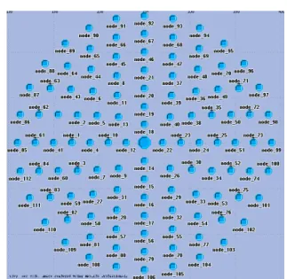
Fig. 5. Topology of 112 sensor nodes and 1 Sink.
To assess the performance of the RBF protocol, a simulation scenario was designed using OPNET® Modeler [17]. We assume that the WSN is deployed within a circular Node 1 Node 4 Node 2 Node 3 Node 41 Node 10 CTS_Response(4) CTS_Response(2) RTS DATA
DIFS SIFS SIFS
Time Time Time Time Time Time
€
t
4€
t
3€
t
2 CTS_Response(3) CTS ACK NAV NAV NAV NAV Backoff Interval slot_time€
CW
max€
t
4€
t
2€
t
3 Time 0 1…
area of a radius of 140 m. A total of 112 sensor nodes are distributed uniformly on the seven circular rings within the area as in Fig. 5. The sink is placed at the center of the area. We note that the topology is meant for this particular study, and the nodes distribution will be deployed in random fashion for our subsequent study as in real life implementation.
We suppose a transmitted signal fades according to classical propagation law in 1/rγ, where r is the transmission distance
and γ is the radio frequency (RF) attenuation exponent. Parameters are chosen in accordance with ITU-R P.1238-1 recommendation document [18] that proposes propagation law for wireless personal area networks. Table II shows the parameters used in the simulation.
TABLEII SYSTEM PARAMETERS
Parameter Value
Data_tx_rate, control data_rate 250 kbits/s
Slot_time 20 µs
Sifs_time 10 µs
Sensor Transmit Power 7 mW [8.45 dBm]
Receiver sensitivity -95 dBm
Sink Transmit Power (Beacon Signal) 1 W [30 dBm] Sink Transmit Power (CTS/ACK) 7 mW [8.45 dBm]
Packet Size 32 Bytes (256 bits)
Packet Generation Rate 10 packets/s Packet Inter-arrival Time Exponential (10 s)
Simulation time 30 s
As an illustration, the received power levels of the transmitted beacon signals for each ring are plotted in Fig. 6.
Fig. 6. RSSI (dBm) for nodes on each ring.
B. Simulation Results
We present simulation results for a sensor topology as in Fig. 5 by evaluating the end-to-end latency between the sensor nodes and the sink. The end-to-end latency refers to the amount of time elapsed when a source node generates a data packet and until the data packet is delivered to the sink. In XLM [2], with a sensor topology of 300 nodes, it considered the simulation based on event that occurs within an event radius of 20 m. In SIF [7], with two sensing fields of 50 and 75 sensors, it considered in each simulation run, only 3 sensors sending packets at a fixed rate to the sink. We considered a large number of sensors sending packets to the sink, i.e., all nodes on each ring at one time. In each
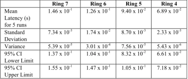
simulation scenario, we let all nodes on each ring (at one time) generate data packets and perform the RTS/CTS frame exchanges before transmitting the data packets towards the sink. For each scenario, the simulation was performed for five runs with five different random seeds. The average end-to-end latencies, standard deviation, variance, 95% confidence interval (CI) lower limit and upper limit are tabulated in Table III (for nodes on ring 7, 6, 5 and 4) and Table IV (for nodes on ring 3, 2 and 1). As an illustration, Fig. 7 gives the end-to-end latencies for one simulation run performed for all the seven scenarios.
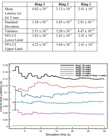
We considered a transmit power of 8.45 dBm for the sensors to let more nodes participate in the contention process for replying a CTS frame. With this power and path loss as in [18], a sensor node can reach its neighbors within a radius of 42 m, i.e., in the vicinity of 2 hops away. Nodes on ring 1 can reach the sink directly and the end-to-end latency is shown to be constant and smallest as expected. When the sink replies to the sensors with CTS/ACK frames, its transmit power is adjusted to be 8.45 dBm in order to avoid other nodes in the network from overhearing the frames which may deplete some of its energy.
For the nodes located on the outer rings that are multi-hops away from the sink, traversing through the inner rings introduce more delays when the sensors perform the contention, retransmission or defer when the medium is not idle. As indicated in the table, nodes on ring 7 which are seven hops away from the sink have the average end-to-latency of 146 ms in order to deliver data towards the sink.
Comparing to some previous works for MAC/Routing protocol that propose a sleep mode to save energy [2], the average end-to-end latency is in the order of 2 to 7 s. In this protocol, during a sleep mode, the sensor cannot sense or transmit information. With many nodes in sleep mode, the end-to-end latency increases due to retransmissions when the sender cannot find any neighbors. The protocols are more suitable for a monitoring application but not for an event-driven WSN. Our research work is meant for an event-event-driven WSN, whereby only some sensors need to send data when event occurs in the environment. Data aggregation technique among the sensors that sense similar events leads to a less number of nodes to transmit if the information is correlated with the transmitting source nodes.
TABLEIII
AVERAGE END-TO-END LATENCY (SECOND) FOR NODES ON RING 7,RING 6, RING 5 AND RING 4 FOR A LOAD OF 10 PACKETS/S
Ring 7 Ring 6 Ring 5 Ring 4
Mean Latency (s) for 5 runs 1.46 x 10⁻¹ 1.26 x 10⁻¹ 9.40 x 10⁻² 6.89 x 10⁻² Standard Deviation 7.34 x 10⁻³ 1.74 x 10⁻² 8.70 x 10⁻³ 2.33 x 10⁻³ Variance 5.39 x 10⁻⁵ 3.01 x 10⁻⁴ 7.56 x 10⁻⁵ 5.43 x 10⁻⁶ 95% CI Lower Limit 1.37 x 10⁻¹ 1.04 x 10⁻¹ 8.32 x 10⁻² 6.61 x 10⁻² 95% CI Upper Limit 1.55 x 10⁻¹ 1.47 x 10⁻¹ 1.05 x 10⁻¹ 7.18 x 10⁻²
TABLEIV
AVERAGE END-TO-END LATENCY (SECOND) FOR NODES ON RING 3,RING 2
AND RING 1 FOR A LOAD OF 10 PACKETS/S
Ring 3 Ring 2 Ring 1
Mean Latency (s) for 5 runs 4.02 x 10⁻² 3.13 x 10⁻³ 2.41 x 10⁻³ Standard Deviation 1.58 x 10⁻³ 5.65 x 10⁻⁴ 2.91 x 10⁻¹¹ Variance 2.51 x 10⁻⁶ 3.20 x 10⁻⁷ 8.47 x 10⁻²² 95% CI Lower Limit 3.82 x 10⁻² 2.43 x 10⁻³ 2.41 x 10⁻³ 95% CI Upper Limit 4.22 x 10⁻² 3.84 x 10⁻³ 2.41 x 10⁻³
Fig. 7. End-to-end Latency (s) for data delivery to the sink for sensor nodes on ring 1, ring 2, ring 3, ring 4, ring 5, ring 6 and ring 7. Packet generation rate of 10 packets/s and Exponential Inter-arrival time with mean of 10 s.
IV. CONCLUSION
In this paper, we have proposed the RBF protocol, which combines the tasks of MAC and routing via cross-layer design, to deliver sensing data from sensor nodes to the sink. Our solution uses RSSI as a parameter for the receiver-based contentions among the next-hop nodes without requirement of global or local state maintenance of the routing tables. In addition, knowledge of the geographical locations of the sensor nodes is not required, and thus eliminating the costly techniques to determine the sensor nodes’ locations. Latency has been considered as an important indicator to analyze the effectiveness of the protocol in this event-driven WSN, and the protocol has been shown to have low latency and robust data delivery. As for the future works, we would like to test the protocol with random network topology and improve the protocol by considering enhancements such as refining the approach so that node closer to the sink should have a higher probability of being picked-up as a next-hop node to forward the data. Energy efficiency technique will be considered such that nodes’ remaining energy levels are taken into account when they participate in the contention process so that the energy consumptions are evenly distributed. Other possible future research works include the study of radio propagation shadowing effects to the protocol and how to alleviate the
congestion among the nodes close to the sink or fairly spread the loads among the nodes.
REFERENCES
[1] I. F. Akyldiz, W. Su, Y. Sankarasubramaniam, and E. Cayirci, “Wireless Sensor Networks: a survey,” in Computer Networks Journal (Elsevier), 38(4):393-422, 2002.
[2] I. F. Akyildiz, M.C. Vuran and O.B. Akan, “A Cross-layer Protocol for Wireless Sensor Networks,” in Proc. Conference on Information Science
and Systems (CISS ’06), Princeton, NJ, March 22-24, 2006.
[3] Holger Füβler, Jörg Widmer, Michael Käsemann, Martin Mauve and Hannes Hartenstein, “Contention-based forwarding for mobile ad hoc networks,” in Ad Hoc Networks Journal (Elsevier), Vol. 1, No. 4, November 2003.
[4] Donggang Liu, Peng Ning and Wenliang Du, “Detecting Malicious Beacon Nodes for Secure Location Discovery in Wireless Sensor Networks,” in Proc. 25th IEEE International Conference on Distributed
Computing Systems (ICSCS’05), 2005.
[5] Dazhi Chen, Jing Deng and Pramod K. Varshney, “On the Forwarding Area of Contention-Based Geographic Forwarding for Ad Hoc and Sensor Networks,” in Proc. IEEE SECON 2005.
[6] B. M. Blum, T. He, S. Son, and J. A. Stankovic, “IGF: A Robust State-Free Communication Protocol for Wireless Sensor Networks,” in
Technical Report CS-2003-11, CS Department, University of Virginia,
2003.
[7] Dazhi Chen, Jing Deng and Pramod K. Varshney, “A State-Free Data Delivery Protocol for Multihop Wireless Sensor Networks,” in Proc.
IEEE WCNC 2005.
[8] M. Zorzi, R.R. Rao, “Geographic Random Forwarding (GeRaF) for Ad Hoc and Sensor Networks: Multihop Performance,” in IEEE Trans. on
Mobile Computing, vol. 2, Oct-Dec. 2003.
[9] Q. Fang, J. Gao, and L. J. Guibas, “Locating and Bypassing Routing Holes in Sensor Networks,” in Proc. of IEEE Infocom 2004, Hong Kong, March 2004.
[10] “IEEE Standard for Wireless LAN – Medium Access Control and Physical Layer Specification, P802.11,” 1999.
[11] T.-C. Hou, V.O. Li, “Transmission range control in multihop packet radio networks,” IEEE Trans. Commun. 34 (1) (1986) 38-44.
[12] N. Bulusu, J. Heidemann, and D. Estrin, “GPS-less low cost outdoor localization for very small devices,” In IEEE Personal Communications
Magazine, pages 28-34, October 2000.
[13] T. He, C. Huang, B. M. Blum, J. A. Stankovic, and T. F. Adelzaher, “Range-free localization schemes in large scale sensor networks,” In
Proc. of ACM Mobicom 2003, 2003.
[14] A.Nasipuri and K. Li, “A directionality based location discovery scheme for wireless sensor networks,” In Proc. of ACM WSNA ’02, September 2002.
[15] A. Savvides, C. Han, and M. Srivasta, “Dynamic fine-grained localization in ad-hoc networks of sensors,” In Proc. of ACM Mobicom
’01, pages 166-179, July 2001.
[16] Giuseppe Bianchi, “Performance Analysis of the IEEE 802.11 Distributed Coordination Function,” IEEE Journal on Selected Areas in
Communications, vol. 18, no.3, March 2000.
[17] OPNET Technologies, Inc., http://www.opnet.com/ [18] Recommendation ITU-R P.1238-1, 1997-1999