Three Telescope Nuller,
based on multi beam injection into single mode waveguide
Anders Karlsson*
a, Oswald Wallner
b, Josep Perdigues Armengol
a, Olivier Absil
ca European Space Agency, Keplerlaan 1, 2200 AG Noordwijk, The Netherlands, b Vienna University of Technology, A-1040 Vienna, Gusshausstrasse 25/389, Austria
c,Université de Liège, 17 Allée du Six Août, B-4000 Sart-Tilman, Belgium,
1. ABSTRACT
Nulling interferometry of exo-solar planets requires as a minimum two telescopes, of which one is phase shifted by 180 degrees, such that the on-axis stellar object is cancelled, while the light from the off-axis planet interferes constructively. Improvement of the nulling performance and the introduction of chopping leads to space interferometers of four or more telescopes and a separate spacecraft dedicated to beam recombination, as currently baselined for Darwin and TPF.
It has recently been demonstrated that the stellar leaks mainly affects the integration times for near-by target stars [c]. Considering that there are only a few near-by targets and that the integrations times for each of these is short compared to that of distant stars, it appears advantageous to simplify the interferometer, by accepting higher levels of stellar leaks for near-by targets.
A simple, chopping nulling interferometer can be obtained by adding one equal size telescope to the basic two telescope nulling interferometer. Modulation is obtained by applying time-varying phase-shifts to the beams before recombination, i.e. inherent modulation [d].
The recombination of 3 multi-axial beams is achieved by coupling into a single mode waveguide, leading to high modulation and coupling efficiencies, and a single focal plane [i]. Linear and circular telescope configurations are proposed and investigated, including a discussion on the need of a separate spacecraft for beam recombination. The associated transmission and modulation maps and efficiencies are calculated and discussed.
2. BACKGROUND
For detection and remote sensing of planets outside our own solar system, i.e. exo-planets, we need to separate the light from the planet and that from its parent star. The required telescope size, capable of resolving the exo-planet from its parent star, becomes unreasonably large. However, by using several separated telescopes of smaller diameters, we can readily separate stellar and planetary light. When all telescopes are pointed to the target star and distributed in a plane, orthogonal to the line of sight, the phase relation between the light from the on-axis object, i.e. the star, and off-axis objects, e.g. planets orbiting the star, will depend on the baseline between the telescopes. The stellar light can then be suppressed by nulling interferometry [e]. In essence this means that achromatic phase shifts are applied to (some of) the beams before recombination such that the on-axis light, in our case: stellar light, is cancelled by destructive interference, while the off-axis planetary light interferes constructively. The required stellar light rejection ratio (105 – 106), imposes severe optical
requirements.
Nulling interferometry will be implemented on the DARWIN spacecraft, a cornerstone mission in the Scientific Satellites Programme of ESA, with a foreseen launch in 2015. The mission has the ambitious mission objectives of: a) detection and characterization of planets orbiting nearby stars, with special emphasis on earth-like conditions and life and b) high resolution imaging by aperture synthesis. The baseline design of DARWIN has six free-flying telescope spacecraft and one
beam-combining spacecraft, possibility augmented by a spacecraft dedicated to ground communication and metrology. The beam combiner and the telescope spacecraft fly in one plane with the telescope spacecraft at equal distance from the beam combiner.
In parallel to the European efforts, the American space agency, NASA, is studying a mission with similar mission objectives, the Terrestrial Planet Finder (TPF). Given the ambitious mission objectives, ESA and NASA have made the first steps towards a collaboration on the final mission, DARWIN / Terrestrial Planet Finder. In 2002 a letter of agreement was signed, detailing how the two agencies will exchange information and cooperate in the preparatory phase of the mission.
Recent analysis [c] indicate that the stellar suppression characteristics of the nulling interferometer can be relaxed, while more emphasize is put on interferometer configurations showing fully constructive interference of the planet light. The results can be explained with the facts that a) the prime noise source, the local zodiacal cloud, is constant for all target stars while b) the stellar leakage decreases as the inverse of the distance squared. Planets orbiting the few nearby stars will, no matter which is the dominating noise source, be detected and characterized relatively fast. While detection and characterization of planets around more distant stars will suffer from the local zodiacal cloud, irrespective of the interferometer’s nulling power. Since most time during the mission is spent observing distant stars the nulling requirement can be relaxed, and the interferometer design simplified.
The nulling interferometer concept as proposed in this paper is a simplification and improvement of the DARWIN baseline design. It should be noted that the identified difficulties of beam-recombination and especially suppression of stellar photons radiated off the single mode waveguide and asymmetry of its fundamental mode, call for further analysis and study.
3. MULTI-AXIAL SINGLE-MODE BEAM RECOMBINATION
To achieve high star light rejection in a nulling interferometer, the signals within both interferometer arms have to be equal to a high degree. This requires a highly symmetric instrument setup and modal wavefront filtering [b].
Modal wavefront filtering by propagation within a single-mode waveguide equalizes the optical fields’ wavefronts. Application of modal filtering in the nulling interferometer has as a result that the quality requirements on other optical components, e.g. the telescopes, on alignment, or – in case of Earth-based instruments – adaptive optics can be relaxed. The associated technology is currently pursued by both ESA and NASA, with the goal to identify materials and technologies for single-mode waveguides in the spectral range from 4 to 20 microns [k, m, j].
The core of a nulling interferometer is its beam recombination unit, usually realized in bulk optics. Because beam splitters are inherently asymmetric and chromatic, a double-pass system is required to achieve symmetry over large spectral ranges. As an example, the Modified Mach-Zehnder beam combiner provides two constructive and two destructive outputs, where the beams at the destructive outputs experience identical transmission [a].
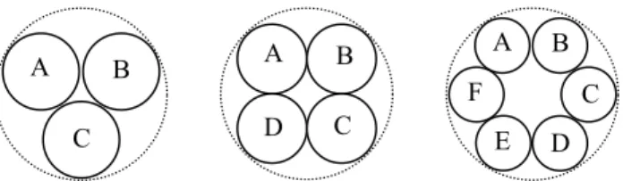
In a multi-axial single-mode beam recombination scheme the beams to be combined are parallel to each other and focussed onto the input face of a single-mode waveguide. For a circular symmetric waveguide a rotational symmetric arrangement of the input beams is required to achieve perfect destructive interference, see Fig. 1. Such an input pupil results in an asymmetric interference pattern, which is perfectly cancelled by the symmetric fiber mode [i]. To minimize the insertion loss, the input pupil should be as compact as possible and the coupling optics optimized for each configuration.
Fig. 1: Layout of circular, equal-sized beams in a circular pupil with minimum spacing.
Minimum insertion loss of about 20% is obtained for a single on-axis beam with optimized coupling optics. Even for zero beam spacing, the losses for the beam configurations as shown in Fig. 1 are clearly higher, ranging from about 33% for three beams to 50% for six beams. However, by cutting each of the input pupils into several equal segments and by recombining them, multiple circular output pupils can be created, see Fig. 2. Each output pupil has a segment from each of the telescopes.
Fig. 2: Three circular pupils are constructed from the original pupils (A, B, and C) by splitting and recombining, such that the constructed pupils have one segment from each original pupil, as indicated in the figure.
Assuming small spacings between the segments, the output pupils can be coupled into the single-mode waveguide with an efficiency close to that of the full pupil. Figure 3 shows the insertion loss of a multi-axial single-mode beam recombination scheme for pupils consisting of two (dashed line) and three (chain dotted line) segments as a function of the beam spacing. The case of the full pupil (solid line) is included as reference.
0.0010 0.01 0.1 0.5 10 20 30 40 50 60 70 80 90 100
relative beam spacing ∆d/d
in se rt io n lo ss [ % ] 3 segments 2 segments full pupil ∆d d
Fig. 3: Insertion loss of a multi-axial single-mode beam recombination scheme for pupils consisting of two and three segments as a function of the relative beam spacing ∆d/d, where d is the beam diameter.
The principle of nulling by multi-beam injection into single mode waveguide has been experimentally verified by Alcatel, using the MAII nulling breadboard [f] operated in “reverse mode”, i.e. the positions of the detector and the source simulator were swaped. Nulling was achieved to a level demonstrating the principle, but without further attempts to optimize its performance. A B C A B C A B D E F C D
C B
A
A
C
B
B
A
C
4. THREE TELESCOPE NULLING INTERFEROMETER
Nulling interferometers require can be constructed with a minimum of two apertures. In order to reduce background noise, and its fluctuations in time, internal modulation [n], is required. By subtraction of the recorded signals it is then possible to extract the science signal from the background noise. The implementation of internal modulation leads to the addition of one or more apertures in the interferometer configuration. As a result, the minimum number of telescopes in a nulling interferometer, with internal modulation, is three.
Three beams cannot be efficiently recombined using traditional beam splitters. However, as demonstrated in the preceding section, three beams can be recombined, with moderate losses, by multi-axial injection into single mode waveguide. Recalling ‘inherent modulation’, as proposed by Absil [d], a variation of internal modulation and performed by application of a time varying phase shift to the beams prior to recombination, one could imagine a nulling interferometer of three apertures, see fig. 4. Selecting equal telescopes sizes, the required phase shifts are 0°, 120° and 240°, in order to cancel the on-axis source. The output signal on the detector varies with time as the applied phase shifts are changed. The phase shifts can, for example, be created by di-electric plates, inserted in the optical paths of the interferometer.
Fig. 4: Schematic beam recombination scheme of a three telescope nuller. Modulation is obtained by alternately applying phase shifts of φ1=0°, φ2=120°, φ3=240° and φ1=0°, φ2=240°, φ3=120°.
The transmission and modulation maps depend on the spatial distribution of the telescopes in the plane of the interferometer. The distribution of the apertures can be arbitrary, making it possible to define circular, linear and any other configurations, all of which have fully constructive interference for specific off-axis angles, except for the linear configuration, which is constrained to equal distance between the telescopes in order to have fully constructive interference. In the following we will investigate the linear and triangular configurations.
φB(t) Focusing Optics Single Mode Waveguide Detector A B C φA(t) φC(t)
5. LINEAR CONFIGURATION
The linear configuration is a special case in that it requires equal spacing between the telescopes in order to give fully constructive interference in a specific direction, see figure 5. Equal optical path length can be ensured either by a) introducing a long delay line and locating the beam combiner on the central spacecraft or b) implementing the beam combiner on a free flying satellite and relaying the beams as proposed for OASIS [g], with the additional requirement that the beam combiner spacecraft forms an equilateral triangle with two of the telescopes. Alternative a) lends itself for an implementation of the interferometer on a structure, where the long delay line is made to a fixed length. Alternative b) allows variable baselines and could, for example, be implemented on four formation flying satellites.
Fig. 5: Two possible beam relay schemes for linear TTN.
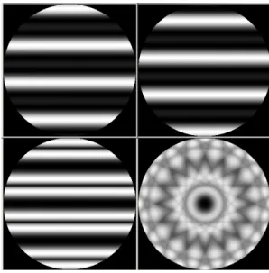
The response of the interferometer with the two sets of phase shifts (0°-120°-240° and 0°-240°-120°) are illustrated in figure 6. The maximum transmission is 67%, including coupling losses due to the mismatch between an Airy pattern and the Gaussian shape of the fundamental mode of the fibre. Due to the fact that the planetary signal is only detected half of the time, the maximum modulation efficiency is reduced to 33.5%. The mean modulation efficiency across the field-of-view is 13.1% and the RMS is 12.8%.
Fig. 6: Top: Transmission maps associated to the two sets of achromatic phase-shifters. These two maps are conjugated by central symmetry. Bottom left: modulation map for the linear TTN. Bottom right: combined modulation map for 8 different orientations of the
array. These maps are obtained at 10µm for a field-of-view diameter of 300 mas and a total baseline of 50 meters.
A B C
A
B
C
B.C.
a)
b)
6. EQUILATERAL TRIANGLE
The equilateral triangle configuration can, with advantage, be implemented on three spacecraft, of which one carries the beam combiner and a telescope. Equal optical path length is ensured by passing the beam via the third spacecraft, see fig. 7, such that each beam travels twice the distance between satellites before reaching the beam combiner. Such scheme obviously adds to the complexity of the relay optics, in that the beams are reflected off the third spacecraft and the optical path is increased.
Fig. 7: The equilateral triangular configuration implemented on 3 spacecraft. All spacecraft carry a telescope and one of them also carries the beam combiner. Equal path length is ensured by passing the beams to the beam combiner via the other spacecraft.
For a given inner working angle, i.e. angular separation in the transmission map between the null and the first constructive fringe, the required minimum inter-satellite distance of the equilateral TTN is larger than for other configurations. As a result the risk of spacecraft collision is reduced. For example, the Dual Chopped Bracewell [h], has for the same inner working angle, an inter-satellite distance 2.67 times shorter.
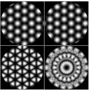
The two transmission maps and the modulation map of the equilateral TTN are illustrated in figure 8. The maximum, mean and RMS modulation efficiencies are the same as for the linear TTN as the same recombination scheme is used.
Fig. 8: Same as Fig. 6 in the case of the triangular TTN. The bottom right modulation map has been obtained by using 3 different orientations of the array.
A C
7. THREE IDENTICAL SPACECRAFT NULLING INTERFEROMETER
In figure 7 the design of spacecraft A would be different from B and C, in that they have different number of relay telescopes. The main difference though, is that satellite A would carry the beam recombination optics, the detector and the associated cooling subsystem, having as an effect that the mass of spacecraft A would be higher. Two satellite types would need to be designed, built and tested, increasing the total project cost and complexity.
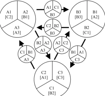
Identical spacecraft would most likely reduce the over-all project cost, but implies that each spacecraft would carry a detector. The combination of three detectors and our earlier discussion on pupils created from segments of circular input pupils, leads to an interferometer of identical spacecraft. At each telescope three pupil segments are taken from the input pupil, each segment is routed differently; clockwise, counter-clockwise and reflected, see fig. 9. Each spacecraft will then receive three sub-pupils, which together form a circular pupil, which can be injected in the single mode waveguide with minimal coupling losses.
Fig. 9: Input pupil splitting, relay scheme and combination of output pupils. The large circles indicate the input pupils (telescopes), with segment references and in brackets, the segment references of the output pupils. The small circles show the relay optics and the carried
segments.
The total number of beams to be received or transmitted from each of the spacecraft equals 12. The beams can be arranged such that they form four groups of three beams, of which two groups are received and 2 groups are transmitted. As a result each spacecraft requires relay optics consisting of two transmit telescopes and two receive telescopes.
The implementation of three focal planes and thus three beam combiners, coolers and other equipment such as RF equipment, would increase the total system mass, but introduce redundancy. For example; a detector or cooler failure would not result in mission loss but would reduce the system efficiency by a factor of one third and; RF equipment could be implemented without redundancy on each spacecraft.
A1 [C2] [B1] A2 A3 [A3] C2 [A1] [C3] C3 C1 [B2] B3 [B3] [A2] B1 B2 [C1] A2 C2 C3 B1 A1 C3 C1 B1 A3 B2 A2 A3 A1 C1 B3 C2 B2 B3
8. AMPLITUDE AND PHASE MATCHING
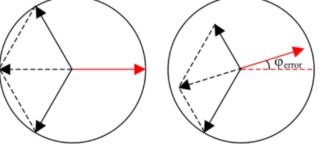
The complex amplitude of the coupled beam has been shown to depend on the matching between input beam and fundamental mode of the modal filter [i]. For example, the tilt of the input beam affects the coupling efficiency, and, if the input beam is decentered around the optical axis, also on the phase of the coupled beam, while lateral displacements of the input beam will only affect the power coupling efficiency (i.e. no impact on the phase of the coupled beam).
Fig. 10: Phase diagrams for two cases showing destructive interference. Solid arrows show input beams and dashed arrows show the sum of two input beams. Leftmost panel: Nominal case where the sum of two beams is 180º phase shifted w.r.t. the third beam. Rightmost panel:
One of the beams has a phase error, ϕerror, which is compensated by adjusting the phase of that beam itself and one other beam, resulting in destructive interference.
These properties may prove useful for fine intensity and phase adjustment. Small residual phase errors, not corrected by the achromatic phase shifter, and amplitude errors could be corrected at injection to the single mode waveguide, by an optical device capable of laterally displacing each of the individual beams in an independent and controlled way. Note that although by laterally shifting only affects the power coupling efficiency, it is also possible to correct phase errors, see figure 10. By properly displacing two of the beams, intensity and phase corrections can be applied simultaneously on the third beam in a TTN configuration.
9. DUAL OUTPUT
As compared to other proposed nulling interferometer configurations, for example the X-array [h] and others, the three telescope nuller, with the simple beam combination scheme as described in section 4, has a low planet signal reconstruction efficiency. This is explained by the fact that the three telescope nuller has a single output as compared to two complementary for the other configurations.
Complementary outputs can be created by recombining the beams as illustrated in figure 10. Each of the three input beams are spilt in two equal intensity beams. The six output beams are then pair-wise recombined with a phase shift of +90º (chop state 1) or -90º (chop state 2). The on-axis stellar light will be transmitted to the outputs with equal intensity, while off-axis light will have an intensity distribution over the outputs as a function of the phase difference incurred as a result of the interferometer’s baseline. For example, a wavefront received at two telescopes with a phase difference of 120º, will be recombined with a phase difference of 210º, resulting in 93% of the total intensity in one of the beam splitter’s outputs. The 3 left outputs from the beam splitters are recombined by multi-axial injection into a single mode waveguide. The beams are phase shifted such that the on-axis object (the star) is cancelled (-120º, 0º and +120º), assuming equal intensity beams. Some off-axis objects will interfere constructively, for example objects with 120º phase difference (chop state 1). Objects with -120º phase difference will interfere destructively on this output, while on the right output from the beam splitters, where 93% of the intensity is directed, they will interfere constructively (chop state 1).
Fig. 10: Modulation scheme with two complementary outputs. The boxes show the applied phase shifts in chop state 1 (first line) and chop state 2 (second line). Note that phase shifts due to reflection are not considered in the above diagram.
By changing the applied phase shifts, or chop state, the intensity distribution on the detectors is reversed, i.e. internal modulation [n] of the signal. Note that ideal beam splitters are not required. However, the 3 beam splitters for intensity splitting should be identical, and the 3 beam splitters used for beam combination should be identical. This could be obtained by cutting the beam splitters from the same piece of beam splitter material.
The modulation maps depend on the position of the telescopes and are thus identical, in terms of shape, to those described above. The maximum modulation efficiency is 93% before injection into the SMW. Creating three circular pupils, composed of a segment from each beam (see fig. 2), for each branch leads to a maximum modulation efficiency of 74 % after injection into the single mode waveguides. This would produce three outputs per branch, i.e. 6 output signals.
+ 90º - 90º 120º -120º + 90º - 90º + 90º - 90º -120º 120º -120º120º -120º120º S/C A S/C B S/C C
10. DISCUSSION AND CONCLUSIONS
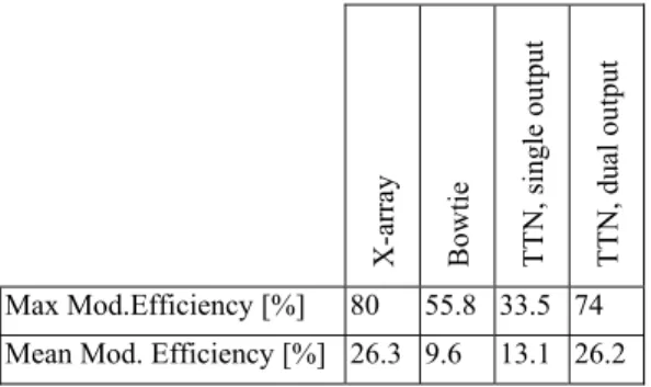
A family of nulling interferometers, based on three telescopes and multi-beam injection into single mode waveguide, has been proposed. Beam combination schemes for single and dual outputs have been proposed. The modulation efficiency of the single output TTN is inferior to the Bowtie [d] and X-array [h], see table 1. However, by creating a second output the modulation efficiency improves, such that the overall performance of the TTN interferometer is comparable to what can be achieved with other interferometer configurations.
The three telescopes of the interferometer configuration may be arbitrarily distributed in the plane orthogonal to the pointing direction. We have examined the linear and equilateral triangle configurations. For the latter configuration, it is not only possible to implement the beam combiner distributed over the three telescope spacecraft, (reducing the number of spacecraft in the formation), but also to make the spacecraft identical, reducing cost associated with development and test of the space system. However, in order to retrieve the weak science signal it may prove beneficial with an irregular distribution of the spacecraft, creating a modulation map with high and low frequencies as the array is rotated around the line of sight. The latter would require a separate spacecraft or a long optical delay line, in order to equalize the optical path lengths of the interferometer.
Assuming a total mass limit of the space interferometer, as imposed by the launcher system, the TTN compares favourably in terms of overall performance. The reason for this is to be found in the fact that the TTN requires fewer spacecraft, having as an effect that more mass and volume can be allocated to the payload. The mass and volume of the beam combination can be assumed to remain constant, while the telescope mass could be increased and thus the collecting area. The so obtained stronger science signal in combination with the somewhat lower efficiency of the TTN, leads to a total science return from the mission comparable to that of above mentioned configurations. Detailed studies of interferometer system performance are currently being pursued by ESA.
X-array Bowtie TTN, sing
le output
TTN, du
al outpu
t
Max Mod.Efficiency [%] 80 55.8 33.5 74 Mean Mod. Efficiency [%] 26.3 9.6 13.1 26.2
Table 1. Mean and maximum modulation efficiency for different configurations,including losses caused by injection into a single mode waveguide.
It is recalled that the TTN, when compared to the Bowtie configuration [d], has less strong suppression of stellar light (proportional to the square of the off-axis angle). However, when comparing the sum of stars, which could be observed during the mission lifetime, the three-telescope configuration compares favourably [c], due to the higher modulation efficiencies of the planetary light.
It is emphasized that multi-axial beam combination has, as yet, not been subject to detailed analysis, especially regarding the possibility to absorb the rejected stellar light in the cladding of the single mode waveguide. This may prove to be a major difficulty and should be verified by test.
11. REFERENCES
[a] Eugene Serabyn, Marc M. Colavita, "Fully Symmetric Nulling Beam Combiners", Appl. Opt. 40, 1668-1671 (2001) [b] Bertrand Mennesson, Marc Ollivier, Cyril Ruilier, "Use of single-mode waveguides to correct the optical defects of a
nulling interferometer", JOSA 19, 596-602 (2002)
[c] Kaltenegger, L., “Requirements on the stellar rejection for the Darwin mission”, these proceedings.
[d] Absil O., Karlsson A., Kaltenegger L., Inherent modulation: a fast chopping method for nulling interferometry, Proc. SPIE, vol. 4852, 2002, p. 431-442.
[e] Angel J.R.P., Woolf N. and Chang, 1986, A space telscope for infrared spectroscopy of earth-like planets, Nature 232, 341.
[f] Haguenauer P. et al. ”Nulling interferometric breadboard using integrated optics beam combiners, preparation to the IRSI/DARWIN mission”, SPIE-4838-133.
[g] JPL publication 99-3, The Terrestrial Planet Finder: A NASA Origins Program to Search for Habitable Palnets, edited by Chas Beichmann, N.J. Woolf, C.A. Lindensmith, May 1999, http://tpf.jpl.nasa.gov/
[h] Lay O. P., Dubovitsky S., "Nulling interferometers: the importance of systematic errors and the X-Array configuration", these proceedings.
[i] Oswald Wallner, Josep Maria Perdigues Armengol, Anders Karlsson, "Multi-axial single-mode beam combiner", these proceedings.
[j] Oswald Wallner, Viatcheslav Artioushenko, Reinhold Flatscher, "Development of silver-halide single-mode fibres for modal filtering in the mid-infrared", these proceedings.
[k] d’Aubigny Drouet Ch.Y., Walker C.K., Golish D.R., "Mid-Infrared spatial filter fabrication using laser chemical etching", these proceedings.
[m] Shaul Shalem, Abraham Katzir, "Silver Halide Infrared Transmitting Core/Clad Fibers with Small Cores", Proc. SPIE 5317 (2004)
[n] Leger, A. et al. “Could We Search for Primitive Life on Extrasolar Planets in the Near Future?”, 1996 Icarus, Volume 123, Issue 2, pp. 249-255