HAL Id: in2p3-00867506
http://hal.in2p3.fr/in2p3-00867506
Submitted on 4 Mar 2014
HAL is a multi-disciplinary open access
archive for the deposit and dissemination of
sci-entific research documents, whether they are
pub-lished or not. The documents may come from
teaching and research institutions in France or
abroad, or from public or private research centers.
L’archive ouverte pluridisciplinaire HAL, est
destinée au dépôt et à la diffusion de documents
scientifiques de niveau recherche, publiés ou non,
émanant des établissements d’enseignement et de
recherche français ou étrangers, des laboratoires
publics ou privés.
G. Olry, F. Chatelet, C. Commeaux, N. Gandolfo, D. Grolet, C. Joly, J.
Lesrel, D. Longuevergne, R. Martret, G. Michel, et al.
To cite this version:
G. Olry, F. Chatelet, C. Commeaux, N. Gandolfo, D. Grolet, et al.. Spiral2 cryomodules B tests
results. 16th International Conference on RF Superconductivity (SRF2013), Sep 2013, Paris, France.
pp.95-99. �in2p3-00867506�
SPIRAL2 CRYOMODULES B TESTS RESULTS
G. Olry
#, F. Chatelet, C. Commeaux, N. Gandolfo, D. Grolet, C. Joly, J. Lesrel, D. Longuevergne,
R. Martret, G. Michel, L. Renard, A. Stephen, P. Szott, IPN Orsay, CNRS-IN2P3 Université
Paris-Sud, Orsay, France
Y. Gomez-Martinez, UJF/CNRS-IN2P3/INPG, LPSC, Grenoble, France
P-E. Bernaudin, R. Beunard, R. Ferdinand, A. Lefevre, GANIL/SPIRAL2, Caen, France
Abstract
Assembly and tests of the SPIRAL2 superconducting linac's cryomodules at CEA/Saclay and IPN/Orsay have now reached cruising speed after having faced a series of problems, among them contamination. 19 cryomodules are composing the whole Linac and IPN Orsay is in charge of the 7 cryomodules B, housing two 88 MHz, beta 0.12 Quarter-Wave Resonators. Three cryomodules have been assembled and successfully tested up to the nominal gradient of 6.5 MV/m for all cavities with also cryogenic losses within specifications. Two of them are fully qualified and already delivered to GANIL. The third one showed misalignment of one cavity which could lead to partial disassembly if needed. This paper presents the results of those cryomodules tests as well as the status of the remaining ones.
INTRODUCTION
GANIL is presently extending its facility with the new SPIRAL2 project which aims at producing heavy radioactive beams of high intensities: it will provide intense beams of neutron-rich exotic nuclei (106–1011 pps
in the mass range 60 to 140) created by the ISOL production method. Many details can be found in [1-3].
The accelerator is based on a multi-beam superconducting linac, composed of two different families of cryomodules, which will deliver 5 mA deuterons up to 40 MeV and 1 mA heavy ions up to 14.5 MeV/u. Recent achievements and updated status of the linac construction and installation can be found in [4].
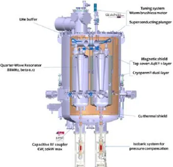
Each cryomodule houses 88 MHz independently-phased QWRs (Quarter Wave Resonator): one beta 0.07 in cryomodule A developed by the CEA/IRFU and two beta 0.12 in cryomodule B designed by IN2P3/IPNO (see Fig. 1). Both institutes have had to deal with pollution problems [5] during several months before getting very good RF and cryogenics performances leading to the first cryomodules qualification [6].
In this paper, we present the last results of the two qualified cryomodules B which have been already delivered to GANIL and the upcoming activities on the five other ones.
2010-2011: BAD RESULTS
IPNO which is in charge of the assembly and the test at 4 K of the 7 cryomodules B (called CMB1, CMB2…CMB7) shall deliver them to GANIL within the specifications listed in Table 1.
We will not describe the cryomodule in this paper. Many details on the cryomodule components and also the tests of the qualification cryomodule can be found in several papers [7-9]. After the good performances of this qualification cryomodule and the delivery of the 6 series cryomodules, we started, beginning of 2010, the assembly of the 3 first cryomodules.
Figure 1: Cryomodule B.
Table 1: Main Specifications for Cryomodule Qualification
Min. accelerating
gradient > 6.5 [MV/m] Pressure sensitivity < -8.0 [Hz/mbar]
Cavity alignment
(cylindricity) < 1.20 [mm] Total dynamic
losses at 4 K and
6.5 MV/m < 36.0 [W] Beam vacuum < 5 10-7 [mbar]
Beam vacuum leaks < 5 10-10 [mbar.l/s]
Pollution and Mechanical Problems
These 3 first cryomodules CBM1, CMB2 and CMB3 have been assembled and tested between September 2010 and June 2011. Unfortunately, we observed two main problems on every cryomodule:
___________________________________________ #[email protected] c○ 2013 by the respecti v e authors
high X-ray dose (> dozens of mSv/h) and cavity quenchs at low accelerating field (often below 4 MV/m)
and high mechanical hysteresis (hundreds of Hz) and “negative” backslash (frequency overshoot while changing the moving direction of the plunger) of the tuning system because of a swinging motion of the plunger (see Fig. 2).
Figure 2: Cavity frequency evolution with respect to plunger displacement.
This led to the disassembly of all cryomodules and, for months, intensive work has been done to track down the origin of the different sources of pollution (see Fig. 3 for example). In parallel, a complete analysis of the tuning system operation has been carried out.
Figure 3: Rust particles inside the pumping tubes and of sparks on the antenna tip marks.
2012: NEW CRYOMODULE PROCESSING
To solve the problems, we changed and improved our cleaning and assembly procedures (Fig. 4), especially in clean room with new high pressure rinsing, active drying and particle counting stages. A quality control plan was established for all components assembled. The RF coupler preparation and conditioning process were improved; its antenna was also electropolished.Figure 4: Particles counting stage and new guiding system for plunger introduction.
To test those improvements in cavity’s preparation and new solutions for the tuning system, we used a special version of the CMB2 cryomodule, called “hybrid”. This cryomodule had one cavity with beta=1 antenna and the other one cavity with its coupler, no common vacuum between the two cavities and additional temperature sensors.
Three tests were necessary to get good RF performances (Accelerating gradient up to 8 MV/m with reduced X-ray doses) and a satisfying tuning system operation with no more “negative” backlash and drastically reduced mechanical hysteresis (see Fig. 5).
Figure 5: Cavity frequency evolution with respect to plunger displacement.
This nice result shown on Figure 5 was obtained at room temperature and needed to be validated at 4 K.
2013: CRYOMODULES QUALIFICATION
Thanks to the good results of the hybrid cryomodule, we started again the assembly and test of the series cryomodules.December 2012: CMB2
CMB2 was tested in December 2012 and showed very good performances: gradients up to 8.3 and 9.2 MV/m and no “negative” backslash during the tuning system operation. We also measured a reduction of the radiation dose with respectively, 3.5 and 0 mSv/h in the cavities at 6.5 MV/m (Fig. 6). The dynamic losses were 12% below the target (i.e. 36 W)
Despite these good performances, the cryomodule was not qualified because of misalignment of the MB03 cavity (cylindricity of 2.54 mm instead of 1.2 mm). This problem is now clearly understood. The cavities were pre-aligned at room temperature before the cooling down process and this operation led to additional tensions into the vertical and horizontal rods used to move the cavity from the outside. The MB03 cavity was “blocked” into a tilted position and no action was possible on the vertical rods. New procedures for the alignment were established: during the assembly, before the cool down and during the alignment process at 4 K. This works very well now.
c○ 2013 by the respecti v e authors
Figure 6: Forward power (left ordinate axis) and Radiation dose (right ordinate axis) vs. Eacc for MB01 (blue diamonds) and MB03 (green diamonds) cavities.
April 2013: CMB1
This cryomodule was the first qualified.
As for CMB2, the RF conditioning process of the couplers was performed at 300 K and 4 K without any difficulties in a short time; between 45 and 90 minutes up to 6 kW in CW mode (Fig. 7). This emphasises rather more all the progresses done during the couplers preparation phases [10].
Figure 7: RF conditioning process up to CW 6 kW (blue curve).
The two cavities reached 8 MV/m. We decided not to exceed this value in order to limit the risk of a potential degradation of the cavity by field emission ignition. As for CMB2, one cavity showed no X-ray at 6.5 MV/m and the second one several mSv/h. The tuning systems reacted nicely as they did with CMB2. The dynamic losses were below 30 W and the cavities were aligned better than 0.35 mm of cylindricity for the worst one.
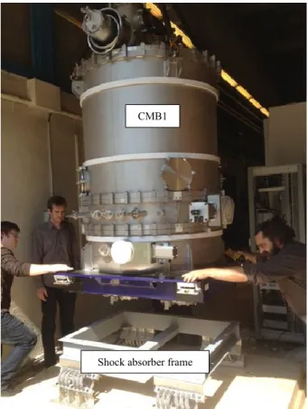
After this qualification, we decided to deliver the cryomodule to GANIL. The transport was done in August with a dedicated truck. The cryomodule is fixed on a specific shock absorber frame (see Fig .8), designed to damp all frequencies higher than 10 Hz and limit the accelerations to a maximum value of 5g in the horizontal planes and 10g in the vertical plane (i.e. specifications for the RF coupler window ceramic). Two 3-axis accelerometers were installed to record the shocks during
the transport. One was set on the truck and the second one onto the cryomodule top plate. About 20 events below 1g absolute were recorded on the cryomodule whereas measurements up to 5 g were recorded on the accelerometer fixed on the truck’s floor.
Figure 8: CMB1 “kiss landing” operation on the shock absorber frame.
September 2013: CMB3
The CMB3 cryomodule was tested end of September-beginning of October and validated in 4 days.
As for CMB1, the RF couplers were conditioned in several hours at 300 K and 4 K without any problems and the tuning systems motions were validated as well (Fig . 9).
Figure 9: MB02 cavity frequency evolution (red curve) and displacement instruction (blue curve) as a function of time.
As illustrated in Figure 10, we saw for the first time no X-ray for both cavities at 6.5 MV/m.
RF conditioning of MB12 cavity coupler
Shock absorber frame CMB1 quench quench c○ 2013 by the respecti v e authors
The total dynamic losses at 6.5 MV/m was about 27 W and the alignment within the specifications (a factor of 3 better).
Figure 10: Forward power (blue diamonds) and Radiation dose (red squares) vs. Eacc for MB02 (upper graph) and MB14 (lower graph) cavities.
This cryomodule has been also shipped to GANIL and only one event was recorded (4.2 g in the horizontal y axis) by the accelerometer fixed onto the cryomodule’s top plate (see Fig. 11). This event is typical from a sudden braking.
Figure 11: Recorded event during the transport of CMB3. Maximum value of 4.2 g was recorded (green curve).
CONCLUSION AND OUTLOOK
Thanks to intensive and tedious work done by the IPNO team mainly on cavity preparation, cryomodule assembly and tuning system operation, two cryomodules have been validated and delivered to GANIL (see Table 2). For the coming weeks, we plan to test again in November CMB2 by applying the same procedure of pre-alignment as for CMB1 and CMB3. Moreover, this cryomodule will be also connected to warm section which will include a Bunch Extension Monitor (BEM), then tested again. There are 2 goals associated with this new experiment: to measure the background level of the BEM with X-rays emitted by the neighbouring cavities.
to verify the connection procedure between the cryomodule and the warm section by opening the cryomodule valve and comparing the X-ray doses before and after connection.
The fourth cryomodule (CMB4) is presently been assembled and should be finished mid of December. The remaining 3 cryomodules will be assembled and tested every 2 months from January 2014. The last transportation should be done just before summer 2014. Table 2: Cryomodules B Tests Results Summary
Unit Specs CMB1
validated CMB2 validated CMB3
Max. acc. Gradient MV/m > 6.5 >8.0 >8.0 >8.0 >8.0 >8.0 >8.0
Total losses @4K, 6.5MV/m W < 36.0 29.5 32 27
Static losses @4k W <12.5 17 18 19
Pressure sensitivity Hz/mbar < 8.0 5.7 5.1 5.3 5 5.2 4.5
Beam vacuum mbar < 5.0e-7 < 6.0e-8 < 6.0e-8 <5.0e-8
Beam vacuum leaks mbar.l/s < 5e-10 < 1e-10 < 1e-10 < 5e-11
Cavity alignment mm 1.2 0.16 0.34 0.88 2.54 0.24 0.38 c○ 2013 by the respecti v e authors
ACKNOWLEDGMENT
The author wants to thank all people at IPNO of the SPIRAL2 cryomodules B team for their hard work which led to these remarkable results.
REFERENCES
[1] http://www.ganil-spiral2.eu.
[2] M-G. Saint-Laurent, “Future opportunities with Spiral2 at GANIL”, AccApp07, Pocatello, July 2007.
[3] M. Lewitowicz, “The SPIRAL2 Project: Physics and Challenges”, Zakopane Conference on Nuclear Physics, Zacopane, September 2008.
[4] R. Ferdinand et al., “Status and challenges of the SPIRAL2 SRF linac”, MOIOA02, these proceedings.
[5] P. Bertrand et al., “SPIRAL2 accelerator construction progress”, Linac 2012, Tel Aviv, September 2012, TH2A02, p. 773 (2012).
[6] P-E. Bernaudin et al., “Assembling, testing and installing the SPIRAL2 superconducting linac”, IPAC 2013, Shangai, May 2013, TPHWO001, p. 3752 (2013).
[7] G. Olry et al., “Development of a beta 0.12, 88 MHz, quarter wave resonator and its cryomodule for the SPIRAL2 project”, SRF05, Ithaca, July 2005.
[8] G. Olry et al., “SPIRAL2 cryomodules: Status and first tests results”, SRF 2009, Berlin, September 2009, THOBAU04, p 495 (2009).
[9] P-E. Bernaudin et al., “Status of the SPIRAL2 superconducting LINAC”, IPAC10, Kyoto, May 2010, MOPD025, p. 732 (2010).
[10] Y. Gomez-Martinez et al., “Last SPIRAL2 couplers preparation and RF conditioning”, TPH054, these proceedings. c○ 2013 by the respecti v e authors