HAL Id: tel-02196785
https://pastel.archives-ouvertes.fr/tel-02196785
Submitted on 29 Jul 2019
HAL is a multi-disciplinary open access
archive for the deposit and dissemination of sci-entific research documents, whether they are pub-lished or not. The documents may come from teaching and research institutions in France or abroad, or from public or private research centers.
L’archive ouverte pluridisciplinaire HAL, est destinée au dépôt et à la diffusion de documents scientifiques de niveau recherche, publiés ou non, émanant des établissements d’enseignement et de recherche français ou étrangers, des laboratoires publics ou privés.
communications professionnelles critiques
Alaa Daher
To cite this version:
Alaa Daher. Optimisation des réseaux cellulaires pour les communications professionnelles cri-tiques. Réseaux et télécommunications [cs.NI]. Université Paris-Saclay, 2019. Français. �NNT : 2019SACLT009�. �tel-02196785�
Thèse
de
doctorat
NNT
:
2019SACL
T009
Optimisation des réseaux cellulaires pour
les communications professionnelles
critiques
Thèse de doctorat de l’Université Paris-Saclay préparée à Télécom ParisTech
Ecole doctorale n◦580:
Sciences et Technologies de l’Information et de la Communication (STIC)
Spécialité de doctorat: Réseaux, Information et Communication
Thèse présentée et soutenue à Paris, le 28 Mars 2019, par
A
LAA
DAHER
Composition du Jury :
Marceau COUPECHOUX
Professeur, Télécom ParisTech Directeur de thèse
Philippe GODLEWSKI
Professeur, Télécom ParisTech co-Directeur de thèse
Rami LANGAR
Professeur, Université Paris-Est Rapporteur
Loutfi NUAYMI
Professeur, IMT Atlantique Rapporteur
Maryline HELARD
Professeur, INSA Rennes Examinatrice
Salah Eddine EL AYOUBI
Maître de Conférences, CentraleSupélec Examinateur
Jérôme BROUET
Ingénieur de Recherche, Thales Examinateur
Jean Marc KELIF
Telecom ParisTech
Laboratory for communication and processing of information (LTCI)
Network and Computer Science department (INFRES)
Optimizing Cellular Networks for Business
and Mission-Critical Communications
Thesis submitted for the degree of
Doctor of Philosophy
by:
Alaa DAHER
Paris, the 28th of March 2019
J
U
R
Y
Marceau COUPECHOUX Supervisor Professor Telecom ParisTech Philippe GODLEWSKI Co-Supervisor Professor Telecom ParisTech Rami LANGAR Reviewer Professor University Paris East Loutfi NUAYMI Reviewer Professor IMT Atlantique Maryline HELARD Examiner Professor INSA Rennes Salah Eddine EL AYOUBI Examiner Associate Professor CentraleSupélec Jérôme BROUET Examiner Research Engineer Thales
Résumé
Les communications professionnelles et critiques sont établies soit entre utilisateurs du secteur de la sûreté publique soit entre acteurs opérants des infrastructures critiques. Du fait des fortes exigences en termes de couverture, de priorité d’accès, de fiabilité et de résilience, sans oublier les services supplémentaires pour les utilisateurs professionnels, ces communications utilisent généralement les technologies PMR (Professional Mobile Radio). Vu la croissance des demandes de services, des changements importants sont attendus dans le domaine de la PMR. Les technologies PMR historiques échouent en effet à fournir des services à débits de données élevés, tels que les services vidéos et le transfert de photos. Ainsi, l’adaptation des technologies utilisées par les opérateurs commerciaux à la PMR apparaît comme une solution prometteuse. D’autre part, la prochaine génération de réseaux cellulaires prévoit une nouvelle variété d’applications et de services, dont les exigences de performances sont hétérogènes. Ils se classent en trois groupes: enhanced Mobile BroadBand(eMBB), massive Machine-Type Communications (mMTC) et Ultra-Reliable Low Latency Communications(URLLC). Récemment, les communications critiques ont été classées dans dans la famille URLLC des cas d’usage car elles sont prioritaires par rapport aux autres types de communications dans le réseau.
Dans ce contexte, nous concentrons à renforcer la couverture des réseaux radio fournissant des com-munications de groupe, service essentiel fournit par les technologies PMR, afin de satisfaire les besoins. Tout d’abord, on évalue la performance des transmissions unicast et multicast, c’est à dire, les transmis-sions Multicast/Broadcast Single Frequency Network (MBSFN) et Single-Cell Point-To-Multipoint (SC-PTM), en termes de qualité radio, d’efficacité spectrale du système et de couverture de cellules, tout en considérant des configurations MBSFN statiques. Puis, nous étudions un modèle analytique pour estimer le Signal to Interference plus Noise Ratio(SINR) dans un réseau MBSFN.
En outre, nous proposons un algorithme simple de répétitions sans requête, comme alternative à l’algoritgme Hybrid Automatic Repeat re-Quest (HARQ), afin d’améliorer la couverture du réseau en présence de communications de groupe. En considérant les caractéristiques du canal radio, ainsi que les contraintes de délai de service, nous justifions que notre modèle fournit un important gain par rapport aux algorithmes de répétitions traditionnels.
Enfin, on évalue le compromis entre la couverture et la capacité d’un réseau utilisant les transmissions multicast, qui évolue en fonction de la taille du cluster de stations serveuses. On formule alors un problème d’optimisation dont l’objectif est de maintenir une probabilité de blocage acceptable du système, tout en maximisant le SINR moyen du groupe d’utilisateurs. Pour chaque groupe, on choisit le cluster de cellules d’une manière dynamique, en se fondant sur la minimisation d’une fonction sous-modulaire, qui prend en compte le trafic de chaque cellule du réseau à travers certains poids, ainsi que le SINR moyen du groupe. Ces poids sont optimisés au moyen de la méthode Nelder-Mead, dans le but de diriger la probabilité de blocage vers un certain seuil. Les résultats obtenus montrent l’importance du regroupement dynamique des cellules dans l’amélioration de la capacité et la couverture du système.
Abstract
Business- and mission-critical communications are communications between professional users either from the public safety sector or operating critical infrastructures. Owing to special coverage, priority access, reliability and resilience requirements, as well as additional services for professional users, these communications are conveyed by Professional Mobile Radio (PMR) networks. Driven by the demand growth, significant changes are taking place in the PMR industry. The existing PMR technologies are indeed not well suited to provide high data rates mobile services like video and photo transfers; hence, the adoption of commercial technologies for mission-critical communications is gaining strong momentum. On the other hand, the next generation cellular networks are envisioned to support a large variety of applications and services with heterogeneous performance requirements, i.e., enhanced Mobile BroadBand (eMBB), massive Machine-Type Communications (mMTC) and Ultra-Reliable Low Latency Communications (URLLC). Recently, mission-critical communications have been classified in a URLLC use case family, characterized by the need to a higher priority over other communications in the networks.
In this context, we focus on enhancing the coverage of wireless networks providing group communications, the main service allowed by PMR networks, taking advantage of the current technologies (e.g. Multimedia Broadcast/Multicast Service), to meet the mission-critical communications needs. First, we evaluate the performance of unicast and multicast transmission techniques, i.e., the Multicast/Broadcast Single Frequency Network (MBSFN) and Single-Cell Point-To-Multipoint (SC-PTM), in terms of radio quality, system spectral efficiency and cell coverage, assuming static MBSFN configurations. Then, we introduce an analytical model to derive an approximate closed-form formula of the Signal to Interference plus Noise Ratio (SINR) in a MBSFN network.
Furthermore, we propose a simple repetition scheme without request, as an alternative to Hybrid Automatic Repeat re-Quest (HARQ), in the aim of improving the network coverage in presence of group communications. By considering the wireless channel characteristics, as well as the service delay constraints, we show that our proposed scheme provides significant gains over traditional repetition schemes.
Finally, we assess the trade-off in the cluster’s size of serving cells which arises between network coverage and capacity in multi-point transmissions. We formulate an optimization problem to maintain an acceptable system blocking probability, while maximizing the average SINR of the multicast group users. For group calls, a dynamic cluster of cells is selected based on the minimization of a submodular function that takes into account the traffic in every cell through some weights and the average SINR achieved by the group users. Traffic weights are then optimized using a Nelder-Mead simplex method with the objective of tracking a blocking probability threshold. Results show the importance of dynamic clustering in improving system capacity and coverage.
Contents
List of Figures ix
List of Tables xiii
1 Introduction 1
1.1 Mission Critical Communications . . . 2
1.1.1 Second Generation (2G) and Professional Mobile Radio (PMR) . . . 4
1.1.2 Fourth Generation (4G) . . . 5
1.1.3 Fifth Generation (5G) . . . 6
1.2 Multimedia Broadcast/Multicast Service . . . 8
1.2.1 MBMS Transmission Techniques . . . 8
1.2.2 System Aspect Differences Between MBSFN and SC-PTM . . . 11
1.2.3 MBMS System Architecture . . . 13
1.2.4 MBMS Channels . . . 15
1.3 Thesis Contributions . . . 17
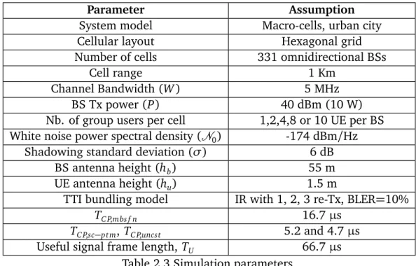
2 SC-PTM or MBSFN for Mission-Critical Communications? 19 2.1 Introduction . . . 20 2.2 System model . . . 21 2.2.1 Network Model . . . 21 2.2.2 SINR Evaluation . . . 22 2.2.3 Spectral Efficiency . . . 24 2.2.4 TTI Bundling . . . 26 2.3 Simulation Results . . . 27 2.3.1 Simulation Settings . . . 27 2.3.2 SINR Distributions . . . 28
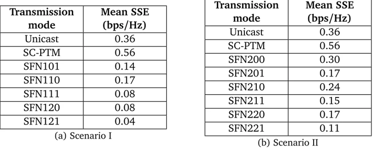
2.3.3 System Spectral Efficiency . . . 30
2.3.5 Cell Range . . . 33
2.3.6 TTI Bundling Gain . . . 35
2.4 Conclusion . . . 37
3 SINR Model for MBSFN Networks 39 3.1 Introduction . . . 40 3.2 System model . . . 41 3.2.1 Network model . . . 41 3.2.2 SINR evaluation . . . 41 3.3 Analytical Approach . . . 43 3.3.1 Analytical model . . . 43
3.3.2 SINR Closed-Form Formula Assuming Shadowing . . . 45
3.4 Simulation Results . . . 48
3.4.1 Simulation Parameters . . . 48
3.4.2 Deterministic Path-Loss . . . 49
3.4.3 Impact of Shadowing . . . 49
3.5 Conclusion . . . 53
4 A Repetition Scheme for MBSFN 55 4.1 Introduction . . . 56
4.2 System Models . . . 57
4.2.1 Link Level Model . . . 58
4.2.2 Rayleigh Fading Channel . . . 58
4.2.3 Rayleigh Fading Simulation Model . . . 61
4.2.4 System Level Model . . . 65
4.3 Link Level Abstraction . . . 65
4.3.1 Overall Architecture . . . 65 4.3.2 Effective SNR . . . 67 4.3.3 BLER Evaluation . . . 68 4.4 Repetition Scheme . . . 68 4.4.1 Design Principles . . . 68 4.4.2 Proposed Scheme . . . 70 4.5 Simulation Results . . . 72 4.5.1 Simulation Parameters . . . 72
4.5.2 Validation of the Link Level Abstraction . . . 73
4.5.3 Repetition Scheme Results for EVA50 channel . . . 74
Contents vii
4.5.5 Cell Radius Gain . . . 79
4.6 Conclusion . . . 83
5 A Dynamic Clustering Algorithm for Multi-Point Transmissions 85 5.1 Introduction . . . 86
5.2 Model and Problem Formulation . . . 89
5.2.1 System Model . . . 89
5.2.2 Traffic Model and Preliminary Results . . . 90
5.2.3 Problem Formulation . . . 94
5.3 A Dynamic Clustering Algorithm . . . 95
5.3.1 Main Routine . . . 95
5.3.2 Group Call Clustering . . . 95
5.3.3 Cell Weights Optimization . . . 100
5.3.4 Complexity Analysis . . . 104
5.4 Simulation Results . . . 104
5.4.1 Simulations Settings . . . 104
5.4.2 Group Call Multi-point Transmission . . . 105
5.4.3 Objective Function and Blocking Probabilities . . . 106
5.4.4 SINR Improvements . . . 107
5.4.5 Performance Evaluation Based Minimum Group SINR . . . 108
5.4.6 Impact of Traffic Intensity . . . 108
5.5 Conclusion . . . 115
Conclusion and Further Work 117 Publications 119 Bibliography 121 Appendix A Submodular Functions Minimization 131 A.1 Introduction . . . 132
A.2 Submodular Functions . . . 132
A.2.1 Notations . . . 132
A.2.2 Definitions . . . 132
A.2.3 Submodular Functions Properties . . . 133
A.3 Submodular Function Minimization . . . 133
A.3.1 Problem Formulation . . . 133
A.3.3 Convex Closure . . . 138
A.4 Equivalent Optimization Problems . . . 140
A.4.1 Minimal Minimizer . . . 140
A.4.2 Linear Optimization over the Base Polyhedron . . . 143
A.5 Min-Norm Algorithm . . . 143
A.5.1 Initialization . . . 143
A.5.2 Linear Optimization over the Base Polyhedron . . . 143
A.5.3 Optimality Test . . . 144
A.5.4 Norm Minimization over the Affine Hull . . . 144
A.5.5 Line Search . . . 145
A.5.6 Algorithm Termination . . . 145
List of Figures
1.1 Mission critical communication users. Source: ETELM. . . 2
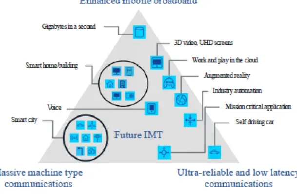
1.2 Next generation mobile networks use case scenarios[23]. . . 7
1.3 MBSFN definitions [34]. . . 10
1.4 MBMS system architecture[43]. . . 14
1.5 Enhanced channel architecture due to MBMS[47]. . . 16
1.6 MBSFN channels mapping[32]. . . 17
2.1 SFN212 configuration. . . 22
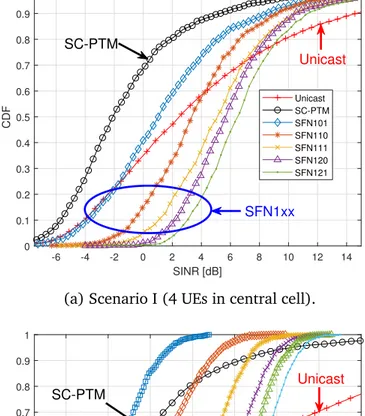
2.2 SINR CDF of different transmission modes. . . 29
2.3 Probability distribution of CQI indexes (Scenario I - 4 UEs/BS). . . 31
2.4 Probability distribution of CQI indexes (Scenario II - 4 UEs/BS). . . 32
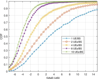
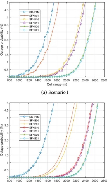
2.5 Minimum SINR CDF of SC-PTM for different numbers of group users per cell. 33 2.6 Outage probability vs. cell range. . . 34
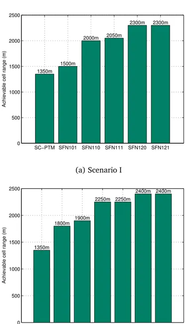
2.7 Maximum cell range (for a 1% outage). . . 35
2.8 Impact of TTI bundling on coverage (1% outage) and SSE. . . 36
3.1 MBSFN network model. . . 42
3.2 Comparison of the analytical model with simulations assuming path-loss exponentsη = 2.7, 3.5 and 4. . . . 49
3.3 Comparison of the analytical model with simulations assuming cell ranges R= 500 m, 2500 m and 5000 m. . . 50
3.4 Comparison of the analytical model with simulations assuming different MBSFN area configurations. . . 51
3.5 Comparison of the analytical model with Monte Carlo simulations and Fenton-Wilkinson approach assuming R= 1500 m, η = 3.5 and σ = 3, 6 and 8 dB. Left: SINR as a function of UE-BS distance. Right: CDF of the SINR. . . 52
4.1 Wave’s arrival angles in Jakes model. . . 63
4.3 Repetition Schemes. . . 70
4.4 Comparison between link level abstraction and link level simulations using Matlab LTE Toolbox or Vienna LTE simulator. . . 74
4.5 Link Level Simulations using Matlab LTE Toolbox. . . 75
4.6 BLER vs. SNR for various frequency hopping steps and time delays and for
L= 1, 2, 3, and 4 repetitions for EVA50 channel, SISO case. . . 76
4.7 SNR thresholds for different repetition schemes at target B L ER= 10−1for SISO case and EVA50 channel (λF in kHz andλT in ms). . . 77
4.8 BLER vs. SNR for MIMO 2x2 with variousλT andλF, and L= 1, 2, 3 and 4
repetitions, for EVA50 channel. . . 78
4.9 BLER vs. SNR for EVA50 and MIMO 2x2 channel, with variousλF,λT = 1 ms and L= 1, 2, 3 and 4 repetitions. . . 79
4.10 SNR thresholds for different repetition schemes at target BLER=10−1 (λ
F in
K Hz andλT in ms), assuming different antenna configurations for EVA50. 80
4.11 SNR thresholds for different repetition schemes at target BLER=10−1 (λ
F in
kHz andλT in ms), assuming different antenna configurations for EPA3. . . 81
4.12 Cell range in MBSFN and SC-PTM urban networks for a target BLER=10−1 and outage probability of 2% (λF in kHz and λT in ms) for EVA50 and SFN120. SC-PTM is with MIMO 4x4 andλF = 720 kHz. . . . 81
4.13 Cell range in MBSFN and SC-PTM urban networks for a target BLER=10−1
and outage probability of 2% (λFin kHz andλT in ms) for EPA3 and SFN120. SC-PTM is with MIMO 4x4 andλF = 720 kHz. . . . 82
5.1 Network model: White cells are part of a MBSFN synchronization area. Cell borders are represented using Voronoi tessellation. Red stars represent User Equipments (UEs) of a group. A (multicast) group of users is served by a cluster of cells of the synchronization area. . . 91
5.2 Simplex operations in R2 (white dots indicate the worst vertices before operations; solid dots indicate new simplex). . . 101
5.3 Evolution of function ΨU along the iterations of Algorithm4. . . 106
5.4 Comparison of min-norm algorithm with greedy clustering to minimize functionΨ. . . . 107
5.5 Evolution of the objective function G, cell weights and blocking probabilities along the iterations of Algorithm6. . . 109
5.6 Clustering evolution along Algorithm 6iterations for a given group. The cluster serving the group is formed by the blue cells, while the white cells are interfering. The links show the best server of each UE. . . 110
List of Figures xi
5.7 Evolution of the objective function G and blocking probabilities along the iterations of globalized bounded Nelder-Mead (NM) algorithm. . . 111
5.8 Comparison of group mean, minimum and UEs SINR CDF of SC-PTM, full MBSFN cooperation transmissions with proposed clustering scheme obtained at the end of Algorithm6. . . 112
5.9 Evaluation of the group minimum and UEs SINR using the proposed scheme, compared to a modified scheme based on exhaustive approach to evaluate functionΨU upon to minimum group SINR. . . 113
5.10 Impact of the traffic load on network performance. . . 114
A.1 Submodular Polyhedron P(F) and base polyhedron B(F) for n = 2 (left) and
List of Tables
2.1 SINR, MCS and Spectral Efficiency mapping table in OFDM downlink
chan-nel[55, Table 7.2.3-1], [56]. . . 25
2.2 TTI bundling model parameters for QPSK, 16-QAM and 64-QAM modula-tions[57]. . . 27
2.3 Simulation parameters. . . 28
2.4 Mean SSE of different transmission modes (4UEs/BS). . . 31
2.5 Mean SSE (in bps/Hz) of transmission modes for different numbers of group users per cell. . . 33
3.1 SINR analytical model simulation parameters. . . 48
4.1 Coherence Bandwidth of typical multi-path fading channels. . . 68
4.2 Coherence time of typical PMR UE speed. . . 69
4.3 Repetition algorithm variables. . . 71
4.4 Link Level simulation parameters. . . 73
Chapter 1
Introduction
Contents
1.1 Mission Critical Communications . . . . 2
1.1.1 2G and PMR . . . 4
1.1.2 Fourth Generation (4G) . . . 5
1.1.3 Fifth Generation (5G) . . . 6
1.2 Multimedia Broadcast/Multicast Service . . . . 8
1.2.1 MBMS Transmission Techniques . . . 8
1.2.2 System Aspect Differences Between MBSFN and SC-PTM . . . 11
1.2.3 MBMS System Architecture . . . 13
1.2.4 MBMS Channels . . . 15
1.1
Mission Critical Communications
Business and mission-critical communications are communications between professional users either from the public safety and security sector (police, army, fire fighters), operating critical infrastructures (like metro or railway companies, airports...), or public utilities (electricity, gas, water), see Figure1.1.
Figure 1.1 Mission critical communication users. Source: ETELM.
Effective communications are the key to a successful response to emergency and disaster situations. Indeed, the ability of the first responder emergency services to communicate among themselves affects the ability to save lives. This is reflected in increasing public investment in mission-critical communication systems. Therefore, these systems have some specific and severe requirements, such that:
• High reliability and availability: as specified in 3rd Generation Partnership Project (3GPP) Release 16, the system shall be available for 99.9999% of time[1].
• Call priority and preemption: the system shall assign different levels of priority to calls and interrupt low priority calls on arrival of high priority calls that do not find available resources.
1.1 Mission Critical Communications 3
• Coverage: coverage plays such a large role in mission-critical communication net-works, since losing the signal can mean a life or death situation. In order to extend coverage range in uplink channel, high transmit power has been enabled by the system in specific bands[2].
• Resilient/Isolated network: any Base Station (BS) should be able to act alone in routing calls between network entities that stay operational, e.g., after a disaster had partially caused some network equipment to fail[3].
• Fast call setup time lower than 300 ms[4].
• Network inter-operability: communications with users located on external networks. Moreover, unlike public cellular networks like Global System for Mobile communications (GSM), Third Generation (3G) or Fourth Generation (4G) mobile networks, mission-critical communication networks are characterized by additional services, e.g. Mission-Critical Push-To-Talk (MCPTT) [5], Mission-Critical Video (MCVideo) [6] and Mission-Critical
Data (MCData)[7] including group call communication with low call setup time, mobile
communication systems for railways[8], maritime communication services [9], etc.
Besides these services, group communications are one of the most important and in-dispensable services of mission-critical communication networks. Group communications provide an efficient management of the rescue teams, and allow sending commands and sharing information with all contributors in a disaster area. Indeed, a public safety commu-nications system provides the means for first responders to accomplish their mission by communicating simultaneously with their collaborators in a variety of media. In such sys-tems, individuals in a fire brigade or a police department are typically organized into groups, with different responsibilities. These groups can be predefined or formed on-demand, may have geographic areas to cover, and may be organized based on types of skills or activities to be performed. Within and across those groups, some individuals with supervisory or dispatch authority and responsibility should be able to manage and coordinate the efforts of the first responders. Further, some individuals may be able to receive multiple group communications simultaneously, using their device to listen to the one with the highest priority as signalled by the system. The network shall then allow the coexistence of many active groups at the same time, and each individual can be registered to many groups at same time. It’s worthwhile to note that communication to group members is not confined to speech, as data messaging (e.g. text, image, video...) can also be sent in parallel to speech, and may be sent from a group member who is not currently speaking.
To meet these critical additional requirements and services, mission-critical communica-tions rely on reliable and secure Professional Mobile Radio (PMR) networks.
In this context, we focus on enhancing the coverage of PMR networks providing group communications, taking advantage of the current technologies (e.g. Multimedia Broad-cast/Multicast Service (MBMS)), to meet the mission-critical communication needs.
In the rest of this chapter, we introduce the main developments in the commercial mobile networks to meet the PMR networks requirements. Then, we show the main features of the MBMS introduced by the 3GPP to convey Point-To-Multipoint (PTM) transmissions. Finally, we provide the main contributions of the thesis.
1.1.1
Second Generation (2G) and PMR
Most of the deployed wireless systems for mission-critical communications are today based on PMR technologies, such as TErrestrial Trunked RAdio (TETRA), TETRA for POLice (TETRAPOL), or Association of Public-safety Communications Officials-Project 25 (APCO P25), meet most of the aforementioned requirements. However, these networks are mainly devoted to provide a wide range of voice services, but have a limited possibility to provide high data rates mobile services like video streaming, files transmission (maps, databases, pictures...), ubiquitous Internet and Intranet access or Device-To-Device (D2D) communica-tion, which have a strong impact on the efficiency and the responsiveness of the emergency services. Therefore, worldwide there is a great interest of governments and organizations involved in public safety and security towards the provision of such wide range added-value services, in PMR networks, in order to improve the situational awareness and enhance the life-saving operations.
Even if some efforts have been done to enhance PMR systems and to offer higher communication capacity, achievements are still behind those made in the commercial world that recently has developed the 3GPP Long Term Evolution (LTE) technology. Hence, there is a great consensus in adapting the LTE technology to provide IP-based broadband services with the security and reliability typical of PMR networks, which answer to the professional and critical communication needs.
Indeed, many railway researches, including the Future Railway Mobile Communication System (FRMCS) project triggered by the International Union of Railway (UIC), estimate that LTE can meet the needs for transferring railway data in the long term[10]. Moreover,
governments in many countries, including the United States, Belgium and the Republic of Korea have also been surveying how to utilize the LTE system for public safety com-munications, either to augment their existing systems, or to provide a future migration path[11,12].
1.1 Mission Critical Communications 5
1.1.2
Fourth Generation (4G)
The adoption of mainstream commercial technologies, such as LTE and Long Term Evolution Advanced (LTE-A), for business- and mission- critical communications has been discussed in literature [13–17]. Initially designed for public networks, the LTE standard needs some
specific enhancements to meet the requirements of PMR. In this context, adopting LTE as PMR broadband technology needs that some specific applications and functionalities requested by railway as well as public safety and security operators, such as MCPTT, dispatch services, priority management, group communications and direct communications, be included in the releases of the 3GPP standard, also guaranteeing interoperability with actual PMR systems. Thus, the 3GPP has been handling various specification items for supporting the public safety features, and technical specification groups in the 3GPP have established such improvements in Release 12 and 13 specifications, which include:
• Group communications: Group Communication System Enabler (GCSE) for LTE[18]
and Mission-Critical Push-To-Talk (MCPTT) over LTE[5] have been introduced into
3GPP specifications in Release 12 and Release 13 respectively, in order to support group communications together with Push-To-Talk (PTT) voice application and its evolution toward multimedia services. Further, the MBMS, introduced in Release 6, to support such communications (see Section1.2).
• Proximity Services (ProSe): in order to enable D2D communications, without the need to have coverage from a network infrastructure, Proximity Services (ProSe) has been introduced by 3GPP under Release 12 [19, 20]. Together with group
communications, D2D communications are among the key requirements for mission-critical voice services.
• Coverage: 3GPP has specified a higher power transmit class in Release 11 to improve system coverage[2].
• Enhanced Evolved Universal Terrestrial Radio Access Network (EUTRAN) sharing: intended to add flexibility in sharing network resources, 3GPP has introduced in Release 12 an enhanced resources sharing mechanism between critical and non-critical users[21].
• Isolated EUTRAN operation: in order to improve network resiliency, 3GPP has intro-duced in Release 13 the isolated EUTRAN operation for public safety to enable any BS to act alone in case of disasters[22].
1.1.3
Fifth Generation (5G)
Nowadays, Fifth Generation (5G) is viewed as the next revolution within the technology industry and has the potential to encompass every aspect of daily life, from a consumer, business, and industry perspective. Besides enhancing the traditional Mobile BroadBand (MBB) use case, 5G is envisioned to support a large variety applications and services, with heterogeneous performance requirements. Thus, the also known next generation mobile networks, will have to cope with a high degree of heterogeneity in terms of services, device classes, deployment types, mobility levels[23], etc.
Indeed, in addition to the classical MBB traffic demands of high throughput and capacity, where 5G networks will provide rates of up to 10 times faster than current 4G networks, it is expected that these networks will have the capacity to connect billions of objects (Internet of Things (IoT) applications), as well as providing new requirements of achieving low latency and high reliability for many services and use cases[24]. These new services are
not only for human communications; actually, Machine-Type Communications (MTC) are gaining a strong momentum, as they pave the road to a broad range of use cases, which can be classified into two main categories:
• Massive Machine-Type Communications (mMTC): consists of large numbers of low-cost, small and low-power devices, with high requirements on scalability and increased battery lifetime, such as sensors and meters, and enables new services such that IoT, building automation, assisted living, etc.
• Ultra-reliable Machine-Type Communications (uMTC): also known as Ultra-Reliable Low Latency Communications (URLLC), they encompass services requiring very high reliability, ultra-reliable low latency (going down to the millisecond level[1,23])
and uninterrupted and robust exchange of data. The URLLC enable real-time control and automation of dynamic processes (e.g. industrial factory automation, smart grid distribution, traffic management and safety), Vehicule-to-anything (V2X) applications. Furthermore, the uMTC have been classified into many use cases families[24]. Such that
the “higher reliability, higher availability and lower latency” use case family, characterized by moderate rates in most cases, and what matters most is that the messages are transmitted quickly and reliably, and that the network and its services are consistently available with minimal downtime; industrial control and drone connectivity are typical areas of this use case family. Another example of uMTC use case families is the “very low latency”, characterized by a system requirement to carrying data very quickly between the sender and receiver; this type of communication is highly needed in e.g. tactile internet[25].
1.1 Mission Critical Communications 7
Consequently, mission-critical communications have been classified in a URLLC use case family, characterized by the need to a higher priority over other communications in the networks, and require some means of enforcing this priority, e.g. fire brigade personnel having a higher priority over other users on the site of the fire. Moreover, use cases that provide coverage and services in remote or catastrophe-stricken area have been included in this family.
Figure1.2illustrates some usage scenarios envisioned for 5G networks.
Figure 1.2 Next generation mobile networks use case scenarios[23].
By this means, 5G networks will lead the revolution of mission-critical communications. For example, with the advanced networking capabilities, first responders will go far beyond basic MCPTT to add group chat, video, file or location sharing. Moreover, fire fighters will be able to share a live video of a disaster site among team members, as well as receive videos from drones, surveillance cameras, planes and satellites in real-time. Going beyond traditional communication modalities, 5G networks will also facilitate the inclusion of other participants into a mission-critical exchange; think about all the sensors which are now becoming part of the communication network, e.g. temperature sensors, humidity sensors, wind speed and direction sensors; each of those “things” can become a life-saving thing, greatly assisting in an important critical mission. We can also see an army of robots being useful in case of nature disasters, or search and rescue operations[26].
The aforementioned studies have outlined the adoption and integration of PMR function-alities, specifications, requirements and applications in LTE and next generation networks. However, the wide coverage is an important and critical requirement for business- and mission-critical communications, while, in contrary to classical mobile networks, capacity is not the main issue in practical deployments of PMR networks, as experienced by ETELM. Thus, more resources can be used to improve system coverage, while maintaining accept-able capacity levels in PMR networks to meet their requirements. Such schemes have not been widely used in classical LTE deployments, owing to the importance of capacity in these networks. In this perspective, we introduce the multicast transmissions in mobile networks in the following section. Then, we evaluate their performance and we propose some optimization techniques to improve system coverage in the following chapters.
1.2
Multimedia Broadcast
/Multicast Service
The Multimedia Broadcast/Multicast Service (MBMS) was introduced in 3GPP Release 6 to provide multimedia services over mobile networks in efficient means by sharing common radio resources among group of users[27]. By utilizing a common channel to send the same
content to multiple receivers, MBMS improves the scalability of broadcast and multicast in cellular networks, and minimizes the usage of network resources.
In order to provide better coverage and throughput for cell edge users, the Multi-cast/Broadcast Single Frequency Network (MBSFN) was introduced in 3GPP Release 9 under the name of evolved Multimedia Broadcast/Multicast Service (eMBMS). Henceforth, for notational brevity, we use the MBMS notation.
In this section, we introduce the MBMS transmission modes, system architecture and the MBMS channels.
1.2.1
MBMS Transmission Techniques
MBMS data can be delivered either by Point-To-Point (PTP) or Point-To-Multipoint (PTM) transmissions[28]. In Point-To-Point (PTP) (or unicast) mode, a dedicated channel is
established with each User Equipment (UE) to carry MBMS information, while in PTM, a common channel is used to simultaneously convey the information to multiple (multi-cast transmission) or all (broad(multi-cast transmission) User Equipments (UEs) requesting the corresponding data. The system level performance of PTP and PTM transmissions has been evaluated in[29], focusing on retransmission strategies. Soares et al. have proposed
1.2 Multimedia Broadcast/Multicast Service 9
in[30] a UE counting mechanism for Universal Terrestrial Radio Access Network (UTRAN)
to decide the switching point between PTP and PTM modes.
Since it is expected that the radio resources increase linearly with the number of UEs receiving the same data in PTP transmission, PTM improves the resource allocation. However, PTM transmission efficiency mainly depends on the UE in the group with worst radio conditions.
The PTM transmission of MBMS data in the EUTRAN uses either Single-Cell Point-To-Multipoint (SC-PTM), or MBSFN. For each MBMS session, the Multi-cell/multicast Coordination Entity (MCE) makes the decision on whether to use SC-PTM or MBSFN in the MBMS service area, defined as the group of cells transmitting the service. In the following sections, we introduce some aspects of these transmission modes.
Multicast/Broadcast Single Frequency Network (MBSFN)
The Multicast/Broadcast Single Frequency Network (MBSFN) is a simulcast transmission technique introduced to support MBMS transmission in LTE networks. In MBSFN, a time-synchronized common waveform is transmitted simultaneously from a set of Base Stations (BSs) using the same resource blocks. The corresponding cells form the so called MBSFN area. This area can be static, i.e., defined a priori by the operator, or dynamic. In this case, the set of transmitting BSs is dynamically adapted to the UE group spatial distribution. In this context, a dynamic clustering algorithm for MBSFN networks is introduced in Chapter5. In such a transmission, the UE receives copies of the signal with different delays, amplitudes and phases depending on the distance to each BS. Therefore, the UE may treat the multi-cell transmissions in the same way as multi-path components of a single-cell transmission without incurring any additional complexity[31]. It can thus benefit from
spatial diversity, increased useful signal power and reduced Inter-Cell Interference (ICI) (since the received signals from neighbor BSs inside the MBSFN area will be considered as constructive signals). In order to further reduce the inter-cell interference, a set of reserved
cellsaround the MBSFN area can be deployed, in which there is no transmission during
active MBSFN subframes. Moreover, MBSFN is designed to only support extended Cyclic Prefix (CP), which reduces Inter-Symbol Interference (ISI) to the UEs and allows the UE to combine signals from different BSs located far away from each other. These properties lead to Signal to Interference plus Noise Ratio (SINR) improvement, especially at cell edge and thus increased cell coverage[32,33]. MBSFN uses the Multicast Traffic CHannel (MTCH)
to convey the data on specific subframes.
MBSFN synchronization area: An area of the network where all BSs are synchronized
in order to perform MBSFN transmissions. MBSFN synchronization areas can support one or more MBSFN areas. On a given frequency layer, a BS can only belong to one MBSFN synchronization area.
Note that the MBSFN synchronization area is independent from the definition of MBMS service area.
Figure 1.3 MBSFN definitions[34].
MBSFN area: The MBSFN area is a specific area where one or multiple BSs, within a
MBSFN synchronization area, transmit the synchronized signals. It includes the BSs which contribute to the MBSFN transmission and advertise its availability, as well as the reserved cells. A BS can be part of several MBSFN areas[35].
MBSFN reserved cell: A cell within a MBSFN area, which does not contribute to the
MBSFN transmission, is called MBSFN reserved cell. It may be allowed to transmit for other services, at limited power, on the resources allocated for the MBSFN transmission in the belonging area, in order to reduce the ICI.
Single-Cell Point-To-Multipoint (SC-PTM)
The Single-Cell Point-To-Multipoint (SC-PTM) was introduced in 3GPP Release 13 as complementary bearer type of MBMS transmission[36]. SC-PTM reuses the MBMS system
architectures (logical entities and interfaces) and relies on PTM transmissions. However, the synchronized multi-BS transmission is abandoned, i.e., PTM transmission is performed on a per-cell basis. If a group of users requesting the same service is distributed over several cells, involved BSs use independently PTM for the users under their coverage and may interfere each other. Contrary to MBSFN, SC-PTM uses the Physical Downlink Shared CHannel (PDSCH), so that the multiplexing with unicast transmissions is more flexible[37]. Furthermore, SC-PTM transmission enhances coverage and transmission
1.2 Multimedia Broadcast/Multicast Service 11
efficiency by enabling the Hybrid Automatic Repeat re-Quest (HARQ) re-transmissions based on the uplink HARQ and Channel State Information (CSI) feedback from connected UEs[38]. SC-PTM can also activate the Transmission Time Interval (TTI) bundling feature
that consists in sequentially transmitting multiple redundancy versions of every transport block to increase the probability of good reception. We study this feature in Chapter2
as it does not increase the transmission delay compared to HARQ, and we introduce an alternative scheme for MBSFN networks in Chapter4.
1.2.2
System Aspect Differences Between MBSFN and SC-PTM
In this section, we show some system aspect differences between MBSFN and SC-PTM transmission modes, in terms of allocation of the transmission area, scheduling and resource allocation, channel utilization and latency.
Static/dynamic MBMS area
As aforementioned, we designated by MBMS area the area where one or multiple BSs transmit the MBMS data, i.e., the set of BSs which are serving the UEs requesting the corresponding service. The provisioning of such area highly depends on the service to be transmitted. For some services (e.g. mobile TV), it is assumed that interested UEs are widely spread over the network and the MBMS should be delivered in a large pre-planned area, therefore, the MBSFN becomes the suitable transmission technology as it assumed that most BSs belong to the MBMS area.
On the other hand, the UEs distribution is quite different in another services (e.g. critical communications), where the interested UEs are concentrated on several (neighbor or non-neighbor) BSs; likewise, some services might be geographically restricted. In both cases, the MBSFN transmission may becomes non-efficient since it may occur in BSs where no interested UEs requesting the service are served by these transmitters; hence, SC-PTM is quite suitable and efficient for these services as the SC-PTM transmission area can be dynamically determined, on a per cell basis, according to the users distribution [37,
39]. Therefore, taking advantage of performance improvements achieved by MBSFN
transmissions, especially in network coverage, the need arises to define an algorithm which defines the MBSFN area dynamically with respect to UEs group conditions (see Chapter5).
Scheduling and resource allocation
For MBSFN, a subset of radio resources (up to 6 subframes per radio frame[40]) could be
channels. However, multiplexing with unicast data in the same subframe is not allowed, even when the amount of the group data to be sent is instantaneously small. Moreover, the MBSFN subframes are rather statically configured according to service data rate, required Modulation and Coding Scheme (MCS) (depends on radio conditions of all UEs group members inside the MBSFN area) and coverage target, and can’t be dynamically adjusted according to the number of active groups and their traffic load. Thus, radio resources configured for MBMS might be unnecessarily wasted when provisioned for some services. However, both SC-PTM and unicast transmissions use PDSCH and they have the same radio frame structure, hence the radio resources could be flexibly shared between these transmission schemes in the same radio frame, leading to prevent any waste in spectrum resources that can be fully utilized[37,41]. Hence, SC-PTM can be seen as a solution to
improve system capacity and scalability compared to MBSFN transmissions (see Chapter2). Although the capacity is not the main issue in PMR, however, SC-PTM transmissions must be considered, in PMR, as normal enablers for multicast transmissions since they allowed some techniques to improve system coverage, e.g. TTI bundling, which are not adopted for MBSFN in current standards. Moreover, SC-PTM may represent a benchmark for a trade-off analysis between system’s coverage and capacity, presented in Chapter5.
Physical channel utilization
Multicast/Broadcast Single Frequency Network (MBSFN) is only transmitted on single antenna port, and it is expected that the reference signals should be redesigned in order to support multiple antenna port transmission for MBSFN. While SC-PTM transmission is more flexible than MBSFN due to the support of multiple antenna port transmission, since it is based on PDSCH, i.e., transmit diversity could be applied for SC-PTM to increase the radio efficiency[37].
Moreover, MBSFN subframes only support extended Cyclic Prefix (CP) to enable the signal combining of the synchronized transmissions from multiple BSs in a large area. However, the longer CP of OFDM symbols implies a lower code rate for a given MCS, or a lower MCS has to be used to achieve the same BLock Error Rate (BLER) (compared to normal CP) for a given SINR, which leads to a system capacity lost. When the MBMS area is small or only consists of one cell, the use of extended CP is actually not needed; thus, SC-PTM is more flexible than MBSFN in such scenario of small areas due to the support of normal CP[42].
1.2 Multimedia Broadcast/Multicast Service 13 Latency
Single-Cell Point-To-Multipoint (SC-PTM) can support shorter latency, comparing to MBSFN, when establishing new MBMS sessions; in fact, the time to setup and notify the receiving group members of the MBMS bearer setup for a new group communication, in MBSFN transmission, is dominated by the Multicast Control CHannel (MCCH) modification period, which can take the value 5.12 s or 10.2 s[37].
Network planning
The network planning and deployment for SC-PTM is quite easier than that of MBSFN, since MBMS data is sent on a per cell basis and synchronization between multiple sites is not required[37].
1.2.3
MBMS System Architecture
Although SC-PTM and MBSFN will bring capacity and Quality of Service (QoS) gains to the mobile networks, their implementations need costly modifications to the network architecture. Therefore, in order to support MBMS operation in radio networks, 3GPP has introduced new logical network entities, as well as user and control plane interfaces to interconnect them. An evolved architecture is then introduced, as depicted in Figure1.4. LTE network is comprised of the access network and the core network, known as Evolved Universal Terrestrial Radio Access Network (EUTRAN) and Evolved Packet Core (EPC) respectively. Within EUTRAN, the BSs are the collectors of the information that has to be transmitted over the air-interface. In the following, we summarize some functionalities of other network entities that contribute in MBMS operation.
Multi-cell/multicast Coordination Entity (MCE)
The MCE is a logical control entity involved in the session control signaling. It is responsible for allocation of time and frequency resources used by BSs in the MBSFN area (refer to Section1.2.1) for multi-cell MBMS transmission, as well as the selection of the MCS, used on the radio bearers, that guarantees the coverage requirements. The MCE is also responsible for services admission control; indeed, it can decides to un-establish the radio bearers of the new MBMS service if the radio resources are not sufficient, or may preempt radio resources from other radio bearers of ongoing MBMS services[32,34]. Furthermore,
it coordinates the transmission of synchronized signals from different BSs, and decides to use SC-PTM or MBSFN (refer to Section1.2.1) in the transmission of the MBMS data. A
Figure 1.4 MBMS system architecture[43].
BS is served by a single MCE, which can be integrated as part of the BS, or as stand-alone entity (as in Figure1.4). Moreover, the dynamic clustering algorithm of the MBSFN area, proposed in Chapter5, can be implemented in the MCE, owing to its crucial role in MBMS session control[34].
eMBMS GateWay (eMBMS-GW)
The eMBMS GateWay (eMBMS-GW) is physically located between the evolved Broad-cast/Multicast Service Center (eBM-SC) and the BS. Its main function is the forwarding of MBMS user data packets to each BS transmitting the service by means of IP multicast, by allocating an IP multicast address, for each MBMS session, to which the BS should join to receive MBMS user data. Furthermore, the eMBMS-GW performs MBMS session control signaling (session start/update/stop) towards the EUTRAN via the Mobility Management Entity (MME) to set up MBMS radio bearers[32,34]. It is logically split into two domains:
the first is related to user plane, while the other is related to control plane. Likewise, it is connected to EUTRAN by two distinct interfaces, namely M1 and M3 respectively.
1.2 Multimedia Broadcast/Multicast Service 15 evolved Broadcast/Multicast Service Center (eBM-SC)
The eBM-SC is the entry point for content providers, or any external broadcast/multicast source, into the Evolved Packet Core (EPC). Indeed, it is the entity in charge of introducing the multimedia content into the network. For this purpose, it plays the role of traffic shaping and authorizing content provider and terminal requests, as well as the scheduling of broadcast and multicast sessions. Also, it controls the security, billing, in addition to the start and end of MBMS transmissions. Finally, the eBM-SC synchronizes the transmitted data among BSs by means of SYNC protocol[32].
1.2.4
MBMS Channels
In SC-PTM, similarly with unicast transmissions, the MBMS data is carried over PDSCH, and the corresponding downlink assignments are dynamically provided by Physical Downlink Control CHannel (PDCCH). Each SC-PTM session is identified by a Group-Radio Network Temporary Identifier (RNTI), shared among a group of UEs to allow them receiving the transmitted MBMS data[44].
On the other side, a MBSFN area can provide many MBMS services. Based on their QoS, these services are classified into groups. Hence, all services in one group, having the same QoS requirement, are multiplexed in time domain and transmitted using the same MCS, by a specific transport channel for MBMS at the Medium Access Control (MAC) layer, so-called Multicast CHannel (MCH), mapped on the Physical Multicast CHannel (PMCH) of the physical layer[34,45,46]. Regarding the air interface, there are two logical channels
related to MBMS in downlink: Multicast Traffic CHannel (MTCH) and Multicast Control CHannel (MCCH). Both channels are mapped on the MCH and used by UEs that receive MBMS traffic[45]. The relationship between the logical, transport and physical downlink
channels for MBMS is shown in Figure1.5.
Some functions of these channels are described in the following sections.
Multicast Traffic CHannel (MTCH)
The MTCH is a PTM downlink channel used to carries data, corresponding to a certain MBMS, to the UEs, via Radio Link Control (RLC) Unacknowledged Mode (UM) due to the broadcast nature of the transmission, where feedback is not available from the UE in the uplink[45,47]. A MBSFN area can support many MBMS services, resulting in multiple
Figure 1.5 Enhanced channel architecture due to MBMS[47].
Multicast Control CHannel (MCCH)
The MCCH is a PTM downlink channel used to provide the MBMS control information of one or several MTCH, from the network to UEs, including the subframe allocation (positions and number) assigned to MCH, as well as the used MCS[45–47]. Note that there is four
MCS allowed for the MCCH: MCS index 2, 7 (both Quadrature Phase Shift Keying (QPSK)), 13 (16-Quadrature Amplitude Modulation (QAM)), 19 (64-QAM)[47].
In each MBSFN area, there is always one MCCH, associated to one or multiple MTCH, multiplexed onto the MCH (as depicted in Figure1.6). For MCCH and MTCH, the UE shall not perform RLC re-establishment when moving between cells of the same MBSFN area [34]. As for the MTCH, MCCH uses RLC UM in the transmission [47].
Multicast CHannel (MCH)
The MCH is used to transport multiple MBMS, multiplex in time-domain, and assigned to one group due to their equivalent QoS requirement, in one MBSFN area.
A MBSFN area contains one or more MCH, and the time in which all MCH share the resources is named Common Subframe Allocation (CSA) and given in the unit of radio frame. The CSA pattern is periodically repeated with the CSA period. The MCH Subframe Allocation (MSA) for every MCH carrying MTCH is defined by the CSA pattern, the CSA
1.3 Thesis Contributions 17
Figure 1.6 MBSFN channels mapping [32].
period and the MSA end, that are all signalled on MCCH. The MSA end indicates the last subframe of the MCH within the CSA period[34].
Physical Multicast CHannel (PMCH)
The MCH, which carries the MBSFN data, is finally mapped into the PMCH. In each PMCH subframe, only one MCH can be allocated. This physical channel has different characteristics than PDSCH, such that the extended CP and the modified reference signal pattern.
Moreover, unlike PDSCH used in SC-PTM transmissions, the advanced link adaptation schemes, such as MCS adaptation to UE Channel Quality Indicator (CQI) and TTI bundling, are not adopted for PMCH in the current 3GPP Releases. We show that, in Chapters2and4, applying such technologies for MBSFN transmissions will lead to a higher spectral efficiency, improved scalability and coverage.
1.3
Thesis Contributions
This thesis primary objective is to propose and evaluate the main techniques that im-prove mobile networks coverage, a crucial requirement for business- and mission-critical communications.
In this context, the aforementioned radio transmission techniques of multicast/broadcast communications presented in Section1.2.1with their main characteristics and differences, are evaluated in Chapter2in terms of radio quality and coverage gain, and their impact on
the system capacity and System Spectral Efficiency (SSE) is shown, under different UEs distribution scenarios and network configurations. Moreover, we show the ability of TTI bundling to trade-off coverage for capacity, so it can provides a flexible solution to improve the network coverage.
Since Multicast/Broadcast Single Frequency Network (MBSFN) is envisioned to be a key technology for business- and mission- critical communications, the need arises to define simple and efficient dimensioning rules for such networks. The SINR is an important key performance parameter since other metrics such as outage probability and capacity can be deduced from it. Thus, in Chapter3, we introduce an analytical model to derive an approximate closed-form formula of the SINR in a MBSFN. The proposed model takes into account ISI due to the different propagation delays between the UE and its serving BSs.
In Chapter4, we propose a simple repetition scheme without request as an alternative to Hybrid Automatic Repeat re-Quest (HARQ) for group communications. When transport blocks are re-transmitted several times, a trade-off arises between coverage and capacity on the one hand, coverage and delay on the other hand. The performance of our scheme is evaluated using a link layer abstraction based on the Mean Instantaneous Capacity (MIC) together with BLER vs. Signal to Noise Ratio (SNR) curves in Additive White Gaussian Noise (AWGN). With this approach, we obtain very quick results for various schemes. We carefully design our repetition scheme by considering the channel characteristics and the service delay constraints. The proposed scheme could be adopted by next generation MBSFN or SC-PTM networks in order to increase the coverage of mission-critical networks. In MBSFN networks, the full cooperation among all cells of an area achieves the highest cooperative gain, but has stringent impact on system capacity. A trade-off in the cluster’s size of serving cells thus arises between high SINR and network capacity. To assess this trade-off, we formulate in Chapter5an optimization problem to maintain an acceptable system blocking probability, while maximizing the average SINR of the multicast group users. For every multicast group to be served, a dynamic cluster of cells is selected based on the minimization of a submodular function that takes into account the traffic in every cell through some weights and the average SINR achieved by the group users. Traffic weights are then optimized using a Nelder-Mead simplex method with the objective of tracking a blocking probability threshold. The proposed clustering scheme is compared to full cooperation and to SC-PTM schemes. Results show the importance of dynamic clustering in improving system capacity and coverage.
Finally, the results of these studies are summarized along with the perspectives for the future work in Section5.5.
Chapter 2
SC-PTM or MBSFN for Mission-Critical
Communications?
Contents
2.1 Introduction . . . . 20 2.2 System model . . . . 21 2.2.1 Network Model . . . 21 2.2.2 SINR Evaluation . . . 22 2.2.3 Spectral Efficiency . . . 24 2.2.4 TTI Bundling . . . 26 2.3 Simulation Results . . . . 27 2.3.1 Simulation Settings . . . 27 2.3.2 SINR Distributions . . . 282.3.3 System Spectral Efficiency . . . 30
2.3.4 Impact of Group Size . . . 32
2.3.5 Cell Range . . . 33
2.3.6 TTI Bundling Gain . . . 35
2.1
Introduction
One of the main services of Professional Mobile Radio (PMR) is the group communication; in general, a number of first responders for public safety, or railway company agents, etc., need to form a group for communicating with each other or sharing the common data for collaboration on their mission. A such service can be seen as a Multimedia Broadcast/Multicast Service (MBMS), firstly introduced by 3rd Generation Partnership Project (3GPP) for Universal Mobile Telecommunication System (UMTS) in Release 6, as a Point-To-Multipoint (PTM) content delivery to provide multimedia services over mobile networks in efficient means by taking advantage of the broadcast nature of the radio channel[48].
Multimedia Broadcast/Multicast Service (MBMS) flows are transmitted either by Mul-ticast/Broadcast Single Frequency Network (MBSFN), or Single-Cell Point-To-Multipoint (SC-PTM). The MBSFN technology is a natural enabler for such services because it offers PTM communications. In this approach, several Base Stations (BSs) transmit the same signal to group users and thus increase their Signal to Interference plus Noise Ratio (SINR), especially at cell edge. In MBSFN, the transmission of MBMS data can occur in cells, in which there are no user interested in receiving the session, thus, radio resource waste can occur. Moreover, the transmitting cells should be synchronized, which imposes additional delays in session’s establishment. SC-PTM has thus been proposed in 3GPP Release 13 as an alternative to overcome these issues. In SC-PTM, multicast transmission is performed on a per cell basis, which aims at increasing the System Spectral Efficiency (SSE)[36].
The performance of MBSFN and SC-PTM has been discussed in literature and recent 3GPP technical reports. In [49], an analytical model for the capacity and coverage
esti-mations in MBSFN transmission were proposed. Alexiou et al. presented in[50] a study
on performance and cost analysis of different MBSFN deployments, but mainly focus on forward error correction impact. Different selection techniques of Modulation and Cod-ing Scheme (MCS) have been evaluated for MBSFN assumCod-ing Channel State Information (CSI) feedback, e.g. in[32,33]. In references [32,33,49,50], SC-PTM is however not
considered.
Some system aspect differences between MBSFN and SC-PTM have been presented in Section1.2.2. Authors of[28,38] focus on the gains brought by Hybrid Automatic Repeat
re-Quest (HARQ). In[28], deployment strategies of MBSFN are not investigated although
they have crucial impact on its performance. The 3GPP report[51] is the closest to our study
in this chapter. A performance comparison of SC-PTM, MBSFN and unicast transmission modes are presented. The authors show that SC-PTM outperforms MBSFN in terms of SSE,
2.2 System model 21
owing to the efficient use of radio resources only in cells in which there are User Equipment (UE) interested in receiving the session. However, the authors didn’t consider the selection of appropriate MCS for each MBSFN session, since the CSI feedback is not adopted by the standard. Also, the trade-off between coverage gain ensured by MBSFN and transmission reliability in terms of outage probability has not been investigated; although this trade-off is crucial for mission critical communications[52].
System aspect differences between multicast transmission modes have been presented in Section1.2.1. In this chapter, we evaluate the performance of MBSFN, SC-PTM and unicast transmissions in different UE’s distribution scenarios and network configurations, in terms of SINR distribution, SSE, outage probability and cell range. We study the trade-off between coverage and reliability, and we provide engineering rules for the deployment of group communication services. We also show the impact of the Transmission Time Interval (TTI) bundling feature.
The rest of this chapter is organized as follows: In Section2.2, we introduce the system model and parameters in Section2.2. Section2.3presents and discusses the simulation results. Finally, conclusions are summarized in Section2.4.
2.2
System model
In this section, we introduce our system model, the SINR and Spectral Efficiency (SE) evaluation formulas of unicast, SC-PTM and MBSFN transmissions, as well as the model used in our study to evaluate the TTI bundling gains.
2.2.1
Network Model
We consider the downlink of a cellular network with omnidirectional BSs implementing either MBSFN, SC-PTM or unicast transmissions. LetX be the set of all cells (or BSs) in the network.
In MBSFN transmission, we consider several network deployment configurations. We designate by "SFNatr" a given configuration, where there are "a" rings of cells with active User Equipments (UEs) requesting the considered service, "t" rings of cells transmitting synchronously the service without active UEs, and "r" rings of reserved cells. In such network, there are also "o" rings of cells which are outside the MBSFN area. LetXa,Xt,
Xr and Xo be the sets of BSs inside cell rings "a", "t", "r" and "o" respectively; hence:
X = Xa∪ Xt∪ Xr∪ Xo. To simplify, let ˙X = Xa∪ Xt. An example of such configuration
Xa
Xt
Xr
Xo
Figure 2.1 SFN212 configuration.
In SC-PTM and unicast transmissions, the MBMS data is transmitted in BSs supporting active UEs, and all other BSs act as interfering transmitters.
2.2.2
SINR Evaluation
In this section, we introduce the SINR formulas for unicast, SC-PTM and MBSFN transmis-sions.
Unicast
In a unicast transmission, the SINR experienced by UE u is given by:
γucst(u) =
g0uP0
P
b∈X \{0}
gbuPb+ N , (2.1)
where b= 0 is the index of the Base Station (BS) providing the maximum receive power to UE u, called serving BS or best server; Pbis the transmit power of BS b; and gbuis the channel
gain between BS b and UE u; andN is the thermal noise power given by [53]: N = N0W,
whereN0 denotes the white noise power spectral density, and W the system bandwidth.
2.2 System model 23
log-normal random variable characterizing shadowing,ξbuis a zero-mean Gaussian random
variable with standard deviationσ in dB; κ is a constant and η is the path-loss exponent. Note that the Inter-Symbol Interference (ISI) is assumed to be negligible in unicast and SC-PTM transmissions, owing to the Cyclic Prefix (CP).
SC-PTM
In a SC-PTM transmission, the SINR of user u is defined in the same way as for unicast transmission since all BSs that do not serve u are interfering:
γsc−ptm(u) = γucst(u). (2.2)
MBSFN
In SC-PTM and unicast transmissions, the signals originating from all BSs except the serving BS are viewed as Inter-Cell Interference (ICI). On the contrary, in MBSFN, the signal received from an BS of the MBSFN area is part of the useful received signal, provided that the propagation delay does not exceed the CP duration.
To account for this, we define the weight function of the useful portion of a received MBSFN signal as[49]: ωbu= 0 τbu< −TU 1+τbu TU −TU ≤ τbu< 0 1 0≤ τbu< TP 1−τbu− TP TU TP ≤ τbu< TP+ TU 0 otherwise (2.3)
whereτbu is the difference in propagation delay between signals from BS b and serving BS 0 at UE u, i.e.,τbu= dbu−d0u
c ; c is the light propagation speed. Variable TU is the duration of
the useful part of Orthogonal Frequency-Division Multiplexing (OFDM) symbol and TP is the duration of the OFDM CP.
Therefore, the SINR experienced by UE u, in a MBSFN transmission, can be expressed as[49]: γmbs f n(u) = P b∈ ˙X ωbugbuPb P b∈ ˙X (1 − ωbu)gbuPb+ P b∈Xo gbuPb+ N . (2.4)
2.2.3
Spectral Efficiency
The Modulation and Coding Scheme (MCS) plays a crucial role in the Spectral Efficiency (SE) evaluation[49,54]. In the downlink channel of Long Term Evolution (LTE) systems,
the Channel Quality Indicator (CQI) index is fed back to the BS in order to assign the appropriate MCS. The estimated CQI index relies on the SINR experienced by the user u and can be obtained by:
CQIu= max{i|γth,i≤ γ(u), for i = 1...M}, (2.5)
where M is the total number of CQI, and is 15 in 3GPP Release 15 specifications[55]; γth,i
is the SINR switching threshold for the CQI i, andγ(u) is the SINR experienced by the user u (i.e. γucst(u), γsc−ptm(u) or γmbs f n(u)). These thresholds depend on transmission
chain parameters, thus, different sets of thresholds have been provided in literature. In[56],
Fan et al. provided a set of thresholds determined with similar system parameters of ours. On the other hand, each CQI index is defined by a modulation and a coding rate fixed in 3GPP standards[55, Table 7.2.3-1]. Therefore, the corresponding spectral efficiency is obtained by multiplying the coding rate by the number of bits sent with the associated modulation; e.g., the efficiency of CQI 3 is given by: 1024193 x2= 0.377.
The SINR thresholds[56], modulation order, code rate and efficiency [55] of each CQI
index are summarized in Table2.1.
In PTM transmissions, the UEs of a group listen to a common channel, share the same time and frequency resources, as well as same MCS. Thus, different MCS selection approaches, under different goals, have been proposed in the literature[32,33], such that:
• The MCS that ensures the maximum SE over all the users of the group. • The MCS that achieves a target SE.
• The MCS ensuring that even the UE with the lowest SINR receive the data.
However, in the context of mission-critical communications, the latter approach is the one that ensures the best coverage, owing to the fact that all UEs, even those with the lowest SINR, will receive the MBMS data. Therefore, in multicast transmissions, we select the MCS based on the minimum SINR among those experienced in a group, from which we determine the SE of the group. Moreover, because of the possible multi-cell transmission, resources are used in several cells for a given group. To take into account these two effects and to be able to compare the transmission schemes, we need to define a System Spectral Efficiency (SSE).
2.2 System model 25 CQI Index Modulation Order Code Rate (x1024) Efficiency (bps/Hz) SINR Thresholdγth (d B) w/ 10% BLER 0 Out of Range 1 QPSK 78 0.1523 -9.478 2 120 0.2344 -6.658 3 193 0.377 -4.098 4 308 0.601 -1.798 5 449 0.877 0.399 6 602 1.1758 2.424 7 16-QAM 378 1.4766 4.489 8 490 1.9141 6.367 9 616 2.4063 8.456 10 64-QAM 466 2.7305 10.266 11 567 3.3223 12.218 12 666 3.9023 14.122 13 772 4.5234 15.849 14 873 5.1152 17.786 15 948 5.5547 19.809
Table 2.1 SINR, MCS and Spectral Efficiency mapping table in OFDM downlink channel[55, Table 7.2.3-1], [56].
Let consider a user u served by the reference cell of index 0. LetU0the group of users
to which u belongs and which are served by BS 0. At least, letUX˙ be the group users that
are served by the MBSFN area of u.
Unicast
In unicast transmissions, the SE (in bps/Hz), SEucst(u), is derived from γucst(u), based on
the appropriate MCS (see Table2.1). Note that SE does not depend on the rest of the group. In order to take into account the fact that the information is sent to every user separately, the SSE is defined by dividing the SE by|U0|, and taking the expectation as follows:
SS Eucst ≜ E[S Eucst(u)
|U0|
] (2.6)
where the expectation is taken over user locations, group characteristics (spatial distribution, size), cells, and channel variations.
![Figure 1.3 MBSFN definitions [ 34 ].](https://thumb-eu.123doks.com/thumbv2/123doknet/2857906.71199/29.892.117.777.335.532/figure-mbsfn-definitions.webp)
![Table 2.1 SINR, MCS and Spectral Efficiency mapping table in OFDM downlink channel [ 55 , Table 7.2.3-1], [ 56 ].](https://thumb-eu.123doks.com/thumbv2/123doknet/2857906.71199/44.892.130.767.160.571/table-sinr-spectral-efficiency-mapping-downlink-channel-table.webp)
![Table 2.2 TTI bundling model parameters for QPSK, 16-QAM and 64-QAM modulations [ 57 ].](https://thumb-eu.123doks.com/thumbv2/123doknet/2857906.71199/46.892.298.621.617.847/table-tti-bundling-model-parameters-qpsk-qam-modulations.webp)