HAL Id: tel-02292877
https://pastel.archives-ouvertes.fr/tel-02292877
Submitted on 20 Sep 2019HAL is a multi-disciplinary open access archive for the deposit and dissemination of sci-entific research documents, whether they are pub-lished or not. The documents may come from teaching and research institutions in France or abroad, or from public or private research centers.
L’archive ouverte pluridisciplinaire HAL, est destinée au dépôt et à la diffusion de documents scientifiques de niveau recherche, publiés ou non, émanant des établissements d’enseignement et de recherche français ou étrangers, des laboratoires publics ou privés.
Optimal Coordination of Chassis Systems for Vehicle
Motion Control
Moad Kissai
To cite this version:
Moad Kissai. Optimal Coordination of Chassis Systems for Vehicle Motion Control. Automatic Control Engineering. Université Paris Saclay (COmUE), 2019. English. �NNT : 2019SACLY004�. �tel-02292877�
NNT
:
2019SA
CL
Y004
OPTIMAL COORDINATION OF
CHASSIS SYSTEMS FOR VEHICLE
MOTION CONTROL
Thèse de doctorat de l’Université Paris-Saclay préparée à l’École Nationale Supérieure de Techniques Avancées et au Groupe Renault École doctorale n◦573 INTERFACES (EDI) Spécialité de doctorat: AutomatiqueThèse présentée et soutenue à Palaiseau, le 17/06/2019, par
M
OADK
ISSAIComposition du Jury :
Tarek Raïssi
Professeur, Conservatoire National des Arts et Métiers
(Cedric-Lab) Président
Valentin Ivanov
Privatdozent, Technische Universität Ilmenau (Department of
Mechanical Engineering) Rapporteur
Olivier Sename
Professeur, Institut polytechnique de Grenoble - Grenoble INP
(GIPSA-lab) Rapporteur
Barys Shyrokau
Professeur Assistant, Delft University of Technology (Intelligent
Vehicles Group - Department of Cognitive Robotics) Examinateur Bruno Monsuez
Professeur, ENSTA ParisTech (U2IS) Directeur de thèse Adriana Tapus
Professeur, ENSTA ParisTech (U2IS) Co-directrice de thèse Xavier Mouton
Docteur, Renault (Systèmes Châssis) Invité Didier Martinez
i
Declaration of Authorship
I, Moad KISSAI, declare that this thesis titled, “OPTIMAL COORDINATION OF CHAS-SIS SYSTEMS FOR VEHICLE MOTION CONTROL” and the work presented in it are my own. I confirm that:
• This work was done wholly or mainly while in candidature for a research degree at this University.
• Where any part of this thesis has previously been submitted for a degree or any other qualification at this University or any other institution, this has been clearly stated.
• Where I have consulted the published work of others, this is always clearly attributed.
• Where I have quoted from the work of others, the source is always given. With the exception of such quotations, this thesis is entirely my own work.
• I have acknowledged all main sources of help.
• Where the thesis is based on work done by myself jointly with others, I have made clear exactly what was done by others and what I have contributed my-self.
Signed: Date:
iii
“We cannot solve our problems with the same thinking we used when we created them.”
v
Acknowledgements
The work presented in this thesis would not have been possible without the close collaboration of many people.
I would like to express my deep gratitude to my research guide, my main re-search supervisor, Professor Bruno Monsuez, for his patient guidance, enthusiastic encouragement and useful critiques of this research work. I have learnt extensively from him, including how to explore new possibilities, how to change the problem perspective and how to approach it methodically.
My special words of thanks should also go to Professor Adriana Tapus, my sec-ond research supervisor, for her valuable and constructive suggestions during the planning and development of every research paper and every step of this work. Her willingness to give her time so generously has been very much appreciated.
My heartfelt thanks to Dr. Xavier Mouton, for believing in my ideas and his assis-tance for pushing the envelope within the teams of Renault while keeping our ego in check. He has been a great mentor these past years.
My grateful thanks go also to Dr. Didier Martinez for his priceless tips in con-trol engineering, and for his help in carrying the experimentations and data post-processing and analysis.
I would also like to extend my thanks to every member of the chassis systems department of Renault for their help in offering the necessary resources in pursuing this research.
I gratefully acknowledge the Group Renault for providing the financial support for this work.
My warmest thanks go to my uncle Abdelbasset and his wife Zakia for keeping the family ties tight and attending every big event despite their busy schedule.
A special thanks to my source of joy, my younger brother that knows always how to put a smile on my face.
Last, but by no means least, I wish to thank my parents for their encouragement throughout my study. Their unconditional moral support helped me to stay always positive and motivated.
vii
Contents
Declaration of Authorship i
Acknowledgements v
List of Figures xvii
List of Tables xix
List of Abbreviations xxi
List of Symbols xxiii
1 General Introduction 1
1.1 Research purposes . . . 3
1.2 Research Contribution . . . 4
1.3 Development process . . . 5
1.4 Dissertation Outline . . . 6
I THE CURRENT APPROACH 9 2 State of Art 13 2.1 Coordination Strategies . . . 14
2.2 Tire Couplings . . . 16
2.3 Vehicle Modeling . . . 18
2.4 Secondary Objectives . . . 20
3 The Downstream Coordination Approach 23 3.1 Control Architecture . . . 23
3.2 System Modelling . . . 24
3.3 Control Synthesis. . . 25
3.3.1 Reference generation . . . 25
3.3.2 Standalone subsystems controllers. . . 26
3.3.3 Coordination strategy . . . 26
Pure Subsumption . . . 27
Largest Modulus Activation . . . 28
Artificial Neural Network . . . 28
Fuzzy Logic . . . 29
viii
II THE UPSTREAM APPROACH 37
4 Control Architecture 41
4.1 Centralized control . . . 41
4.2 Supervisory control. . . 42
4.3 Multi-layered architecture . . . 43
4.4 Contributions . . . 45
5 Global Vehicle Modelling 47 5.1 Multi-body approach . . . 47
5.2 Vehicle dynamics . . . 48
5.2.1 Dynamic torsor calculation . . . 49
Linear equations of motion . . . 49
Angular equations of motion . . . 51
5.2.2 Exterior forces torsor calculation . . . 53
The dynamic resultant theorem . . . 54
The dynamic moment theorem . . . 54
5.2.3 The sprung mass dynamics . . . 55
5.3 Model simplification and validation . . . 56
5.4 Contributions . . . 63
6 Tire Modeling Review 65 6.1 Tire physical fundamentals . . . 66
6.1.1 Friction . . . 66
6.1.2 Longitudinal Force . . . 67
6.1.3 Lateral Force . . . 68
6.1.4 Global Friction Force . . . 69
6.2 Tire behavioral models . . . 70
6.2.1 Empirical Models . . . 70
Holmes Model . . . 70
The Magic Formula of Pacejka . . . 71
Brach equations for combined slip . . . 72
Kiencke’s Model . . . 73
6.2.2 Theoretical Models . . . 74
The Brush model . . . 74
The Brush Model Derivatives . . . 79
The physical model of Dugoff . . . 81
Modified Dugoff Model . . . 81
LuGre Model . . . 82
Gim’s Model . . . 82
6.2.3 Comparison. . . 83
6.3 Tire physical models linearization . . . 84
6.3.1 Longitudinal force linearization . . . 84
6.3.2 Lateral force linearization . . . 85
6.3.3 Dynamic saturation. . . 86
6.3.4 Summary . . . 86
6.4 Simulation and analysis of the linearized model . . . 87
6.4.1 Brush-based and Dugoff-based linearized models comparison 87 6.4.2 Linearized Dugoff-based model evaluation . . . 88
6.5 Tire models comparison . . . 89
ix
6.5.2 Case of Pure Side Slip. . . 89
6.5.3 Case of Combined Slip . . . 90
The Longitudinal Force . . . 90
The Lateral Force . . . 91
6.5.4 Tire models’ assignment. . . 92
Vehicle Dynamics Simulation . . . 92
Vehicle Motion Control . . . 92
Vehicle States Estimation . . . 93
Tire Construction . . . 93
6.6 Validation and relevance of the new tire model . . . 94
6.6.1 Comparison of linear models . . . 94
6.6.2 Further improvements . . . 97
6.6.3 Controllability . . . 98
6.6.4 Relevance of the new tire model . . . 98
6.7 Contributions . . . 99
7 Friction Circle Estimation 101 7.1 Tire normal forces . . . 101
7.2 Friction estimation strategy . . . 102
7.2.1 Tire Slip . . . 105 Longitudinal slip . . . 105 7.2.2 Side-slip. . . 106 7.2.3 Tire Forces . . . 106 7.3 Accelerations Estimation. . . 107 7.4 Contributions . . . 107
8 Robust Control Synthesis 109 8.1 High-level control . . . 109
8.1.1 H∞ design guidelines . . . 110
Definition . . . 110
Control specifications interpretation . . . 110
Explicit uncertainty . . . 113
Control synthesis . . . 114
Case of Multi-Inputs Multi-Outputs (MIMO) systems . . . 116
Practical drawbacks and improvements . . . 116
8.1.2 µ Synthesis . . . 117
8.2 Low-level control . . . 118
9 Control Allocation 121 9.1 Static Control Allocation (CA) . . . 122
9.1.1 Ganging . . . 122 9.1.2 Daisy chaining . . . 122 9.2 Dynamic CA . . . 123 9.2.1 Precomputed laws . . . 123 9.2.2 Repeated optimization . . . 124 III APPLICATIONS 129 10 Case of ARS-VDC Coordination 133 10.1 Chassis Systems Presentation . . . 133
x
10.1.2 Braking-based Vehicle Dynamics Control . . . 134
10.2 Downstream Approach. . . 134
10.2.1 Control Architecture . . . 135
10.2.2 System Modelling . . . 135
Active Rear Steering (ARS) transfer function . . . 137
Vehicle Dynamics Control (VDC) transfer function . . . 137
10.2.3 Control Synthesis . . . 138
Yaw rate reference . . . 138
Coordination strategy . . . 139
Controllability analysis . . . 140
Subsystems’ Controllers synthesis . . . 141
10.3 Upstream Approach . . . 143 10.3.1 Control Architecture . . . 143 10.3.2 System Modelling . . . 144 Tire forces . . . 145 Generalized forces . . . 146 Effectiveness matrix . . . 146 10.3.3 Control Synthesis . . . 147 High-level controller . . . 148 CA strategy . . . 148 Low-level controllers . . . 153
10.4 Comparison of coordination approaches . . . 154
10.4.1 Matlab/Simulink R Simulations . . . 155
Rapid lane changing . . . 155
ARS failure in slalom maneuver. . . 156
Random braking while steering . . . 157
10.4.2 Amesim R Simulations . . . 159
µ-split maneuver . . . 160
ARS failure . . . 161
10.4.3 Co-simulation results. . . 163
Comparison of methods when no failure - ISO 3888-1:1999(E) 164 Comparison of methods when failure . . . 166
Comparison of CA solvers. . . 168
Multi-behavioral CA . . . 169
10.5 Conclusion . . . 172
10.6 Contributions . . . 173
11 Case of ARS-VDC-RTV Coordination 175 11.1 Vehicle Motion Control . . . 175
11.1.1 High-Level Control . . . 175
The Relative Gain Array (RGA) . . . 176
Bode Diagrams . . . 177 Controller Design . . . 178 11.1.2 Middle-Level Control . . . 180 11.1.3 Low-Level Control . . . 181 11.2 Co-Simulation Results . . . 181 11.2.1 Control Robustness . . . 181
Linear Time InvariantH∞controller . . . 181
Gain-scheduledH∞ controller . . . 183
Relevance of lateral velocity control . . . 184
xi
11.3 Conclusion . . . 188
11.4 Contributions . . . 189
12 Case of Autonomous Vehicles with EPAS-VDC-4WD-TV 191 12.1 System Modeling . . . 191
12.2 Vehicle Motion Control . . . 192
12.2.1 High-Level Control . . . 193
12.2.2 Middle-Level Control . . . 194
12.2.3 Low-Level Control . . . 195
12.3 Tunable Motion Behavior. . . 196
12.3.1 Reference Tuning . . . 196
12.3.2 Tuned CA . . . 197
12.4 Co-Simulation Results . . . 198
12.4.1 Relevance of Advanced Chassis Systems . . . 198
Without Torque Vectoring . . . 198
With Torque Vectoring . . . 200
12.4.2 Motion Feelings Tuning . . . 201
First Approach: Reference Tuning . . . 201
Second Approach: Tuned CA . . . 204
Mixed Approach . . . 204
12.5 Conclusion . . . 206
12.6 Contributions . . . 206
13 Experimental Results: A First Feedback of the ARS-VDC Case 209 13.1 Modeling Methods . . . 210
13.1.1 Experimental Identification . . . 211
The 4-Wheel Steering (4WS) system identification . . . 211
The VDC system identification . . . 214
13.1.2 Analytic Modeling . . . 216
13.2 Robust Control Design . . . 217
13.2.1 H∞ Synthesis. . . 217 13.2.2 µ Synthesis . . . 218 13.2.3 Comparison. . . 218 13.3 CA . . . 221 13.4 Results . . . 222 13.4.1 Control Robustness . . . 222 13.4.2 Benefits of Optimal CA. . . 225 13.5 Conclusion . . . 226 13.6 Contributions . . . 226
14 Relevance of Optimal Control Allocation for Future Vehicles 231 14.1 Relevance of the New Classification . . . 231
14.2 Necessity of a More Accurate Tire Model . . . 232
14.3 Comparison of the two approaches . . . 232
14.3.1 Complexity . . . 232
14.3.2 Cost . . . 233
14.3.3 Safety . . . 233
14.3.4 Potential. . . 235
xii
14.5 Summary . . . 237
15 General Conclusion 239 15.1 Contributions . . . 239
15.2 Future Works . . . 241
15.2.1 Real vehicle implementation . . . 241
15.2.2 Robustness-Performance Compromise . . . 241
15.2.3 Adaptability to Actuators’ Aging . . . 242
15.2.4 Adaptability to Friction Change . . . 242
Machine Learning . . . 242
Robotic Vision . . . 243
New Sensor Technology . . . 243
15.2.5 Multi-Sense . . . 244
Motion References . . . 244
CA Tuning . . . 244
Motion Feelings Formalization . . . 246
15.2.6 Architecture Standardization and Openness . . . 246
Publications 251
xiii
List of Figures
1.1 V-model for over-actuated control system design . . . 6
2.1 Time-line of active safety systems introduction in passenger cars . . . 13
2.2 Possible categories of tire modeling approaches . . . 16
3.1 Structure of the downstream coordination approach . . . 23
3.2 Decentralized control structure . . . 24
3.3 The bicycle model . . . 25
3.4 Simplified control architectures when design is made independently . 27 3.5 The control architecture that should be considered in a downstream approach . . . 27
3.6 Pure Subsumption coordination . . . 27
3.7 Largest Modulus Activation coordination . . . 28
3.8 Artificial Neural Network coordination . . . 29
3.9 Fuzzy Logic coordination . . . 29
3.10 Benefits of a coordinated control in the gg-diagram . . . 31
3.11 Signal flow for a hybrid electric vehicle motion control . . . 33
3.12 Autonomous driving systems in “the Next Two concept" . . . 39
3.13 The possible future intelligent chassis . . . 40
4.1 Structure of the upstream coordination approach . . . 41
4.2 Centralized control structure. . . 42
4.3 Supervisory control structure . . . 42
4.4 Multi-layered control architecture . . . 43
4.5 General block diagram of the integrated vehicle motion control . . . . 45
5.1 Vehicle Axis System (ISO 8855-2011) . . . 47
5.2 The sprung and unsprung masses decomposition . . . 48
5.3 14-DOF vehicle dynamic model . . . 53
5.4 The 15 DOF chassis of Amesim . . . 56
5.5 3D aspect of the Magny-Cours race track with hills area . . . 57
5.6 Magny-Cours trajectory . . . 57
5.7 Validation of the vehicle model: longitudinal speed . . . 61
5.8 Validation of the vehicle model: lateral speed . . . 61
5.10 Validation of the vehicle model: roll velocity . . . 61
5.9 Validation of the vehicle model: vertical velocity of the sprung mass . 62 5.11 Validation of the vehicle model: pitch angle . . . 62
5.12 Validation of the vehicle model: yaw rate . . . 62
6.1 ISO tire coordinate system . . . 66
6.2 Indentation phenomenon . . . 66
6.3 Adhesion phenomenon. . . 67
6.4 Friction mechanisms.. . . 67
xiv
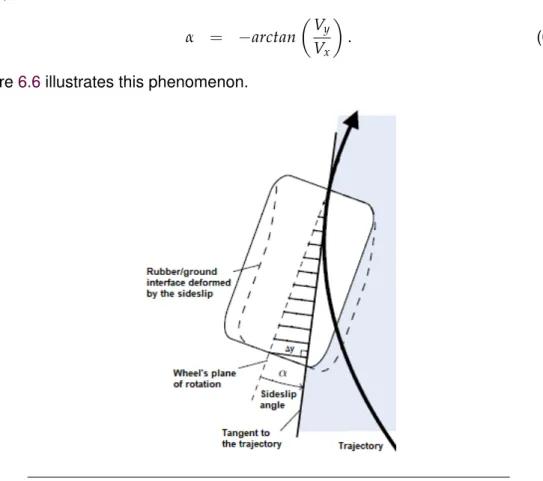
6.6 The side-slip. . . 69
6.7 The friction ellipse concept . . . 70
6.8 Combined side force and brake force characteristics . . . 70
6.9 Forces interactions in a combined slip . . . 72
6.10 Friction coefficient for different surface types. . . 74
6.11 The Brush model . . . 75
6.12 Side view of Brush model when braking . . . 76
6.13 Top and side view of Brush model at pure side-slip . . . 76
6.14 Brush model deformation at combined slip . . . 77
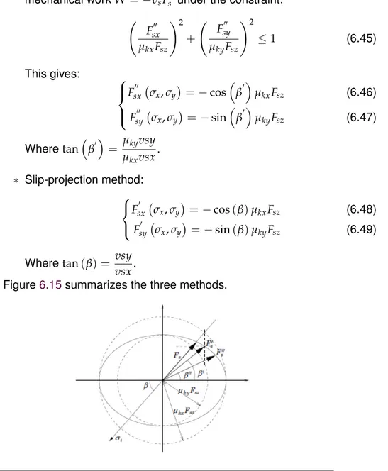
6.15 Illustration of methods to describe kinetic friction in case of anisotropic friction . . . 79
6.16 Comparison of models’ longitudinal force shapes in combined slip . . 84
6.17 Comparison of Pacejka model with both linearized models in com-bined slip . . . 87
6.18 Variation of the longitudinal force slope with respect to side-slip angle (Linearized Dugoff-based model) . . . 88
6.19 Variation of the lateral force slope with respect to longitudinal slip (Lin-earized Dugoff-based model) . . . 88
6.20 Comparison of tire models in case of pure longitudinal slip . . . 89
6.21 Comparison of tire models in case of pure side-slip . . . 90
6.22 Comparison of tire models in case of combined slip. . . 91
6.23 Comparison of tire models in case of combined slip. . . 91
6.24 Wavy sipes used for water evacuation . . . 94
6.25 The chassis model of 15 degrees of freedom in Amesim environment 95 6.26 Amesim comparison of Pacejka model with linearized models - longi-tudinal force. . . 96
6.27 Amesim comparison of Pacejka model with linearized models - lateral force . . . 96
6.28 Amesim comparison of Pacejka model and linearized models with and without transient behavior . . . 97
6.29 Linearized tire module with varying-parameters . . . 99
7.1 The friction ellipse concept. . . 101
7.2 Normal forces on tires in left hand cornering while braking . . . 103
7.3 The friction coefficient estimation method . . . 104
8.1 Illustrative system in a closed loop . . . 110
8.2 Typical shape ofTr→ewith its weighting functionW1 . . . 112
8.3 An illustrative real closed loop system . . . 113
8.4 Example of a double criteriaH∞ problem . . . 114
8.5 H∞standard problem . . . 115
9.1 Schematic representation of daisy-chain method . . . 123
10.1 Active Rear Steering Actuator . . . 134
10.2 Differential braking system. . . 134
10.3 Structure of the downstream coordination approach . . . 135
10.4 Downstream control architecture scheme in case of ARS-VDC coor-dination . . . 138
10.5 Comparison of ARS and VDC angle commands. . . 140
10.6 Variation of the vehicle natural frequency with respect to the longitudi-nal speed . . . 142
xv
10.7 Structure of the upstream distribution approach . . . 144
10.8 The four-wheeled planar vehicle model. . . 147
10.9 Upstream control scheme in case of ARS-VDC coordination. . . 148
10.10 Front wheel steering profile for a rapid lane changing . . . 155
10.11 Yaw rate response for a rapid lane changing . . . 155
10.12 Rear steering angle in a rapid lane changing . . . 156
10.13 Front lateral force in a rapid lane changing . . . 156
10.14 Rear steering angle when failure . . . 156
10.15 Yaw rate when rear steering failure . . . 157
10.16 Brake forces for the upstream approach in case of ARS failure . . . . 157
10.17 Vertical loads taken account of in upstream approach . . . 158
10.18 Yaw rate response in random braking . . . 158
10.19 Rear steering angle while random braking . . . 158
10.20 Cornering stiffness affected by random braking . . . 159
10.21 Amesim high-fidelity vehicle model . . . 160
10.22 Yaw rate control comparison - µ-split maneuver . . . 160
10.23 Brake torques comparison - µ-split maneuver . . . 161
10.24 Lateral rear tire force saturation - µ-split maneuver . . . 161
10.25 Yaw rate control comparison - ARS failure . . . 162
10.26 Brake torques in the downstream approach - ARS failure . . . 162
10.27 Brake torques in the upstream approach - ARS failure . . . 163
10.28 Co-simulation procedure . . . 163
10.29 Double lane-change track . . . 164
10.30 Comparison of the proposed method and the classical one when no failure . . . 165
10.31 Rear steer angle when no failure . . . 165
10.32 VDC activation when no failure . . . 165
10.33 Number of iterations of the CA algorithm at each sampling time when no failure . . . 166
10.34 Rear steer angle when ARS fails . . . 166
10.35 Comparison of the proposed method and the classical one when ARS fails . . . 167
10.36 Comparison of the VDC activation in the proposed method and the classical one when the ARS fails . . . 167
10.37 Number of iterations of the CA algorithm when there is a failure . . . 167
10.38 Fault-tolerance feature of the control logic . . . 168
10.39 Comparison of CA algorithms one when ARS fails. . . 169
10.40 VDC activation using CGI algorithm when ARS fails . . . 169
10.41 Longitudinal acceleration depending on driving behavior . . . 170
10.42 Lateral acceleration depending on driving behavior . . . 170
10.43 Vehicle’s yaw rate depending on driving behavior . . . 170
10.44 Longitudinal speed depending on driving behavior. . . 171
10.45 Front-left tire braking torque depending on driving behavior. . . 171
10.46 Rear steering angle depending on driving behavior . . . 171
10.47 Rear lateral tire stiffness depending on driving behavior . . . 172
11.1 Vehicle motion multi-layered control architecture . . . 175
11.2 Bode diagrams for the longitudinal velocity. . . 177
11.3 Bode diagrams for the lateral velocity . . . 177
11.4 Bode diagrams for the yaw rate . . . 178
xvi
11.6 Yaw rate control with different crossover frequencies . . . 182
11.7 Different controllers for the yaw rate . . . 182
11.8 Different controllers for the yaw rate . . . 183
11.9 Various speed control using GSH∞ . . . 183
11.10 Lateral speed control using GSH∞ . . . 184
11.11 Yaw rate control using GSH∞ . . . 184
11.12 Illustration of the difference between motion behaviors . . . 185
11.13 ISO 3888-1:1999(E) standard with friction variation . . . 186
11.14 Longitudinal speed control when vertical dynamics are ignored . . . 186
11.15 Lateral speed control when vertical dynamics are ignored . . . 186
11.16 Yaw rate control when vertical dynamics are ignored . . . 187
11.17 Longitudinal speed control when vertical dynamics are considered . 187 11.18 Lateral speed control when vertical dynamics are considered . . . . 187
11.19 Yaw rate control when vertical dynamics are considered . . . 188
11.20 Importance of vertical dynamics for friction estimation. . . 188
12.1 The global control architecture . . . 193
12.2 Magny-Cours trajectory with the maximum performance of a vehicle without torque vectoring . . . 199
12.3 Case of vehicle’s loss of control when no torque vectoring is ensured . 199 12.4 Maximum speed tracking with Torque Vectoring . . . 200
12.5 Engine torques distribution at Magny-cours . . . 200
12.6 Braking torques distribution at Magny-cours . . . 201
12.7 Maximum yaw rate tracking with Torque Vectoring . . . 201
12.8 Trajectories in all simulations . . . 202
12.9 Yaw rate responses in case of reference tuning . . . 202
12.10 Steering wheel angle in case of reference tuning . . . 203
12.11 Engine torques in case of reference tuning . . . 203
12.12 Lateral acceleration in case of reference tuning . . . 203
12.13 Lateral acceleration in case of CA tuning . . . 204
12.14 Yaw rate responses in case of CA tuning . . . 204
12.15 Steering wheel angle in case of CA tuning . . . 205
12.16 Lateral acceleration in case of mixed tuning . . . 205
12.17 Steering wheel angle in case of mixed tuning . . . 205
13.1 The prototype experimented. . . 209
13.2 Real yaw rate response of the vehicle using only a PI for the ARS. . . 210
13.3 Real ARS actuator using only a PI . . . 210
13.4 The identification problem in an over-actuated vehicle . . . 212
13.5 Comparison of the measured response and the estimated ones . . . . 212
13.6 Comparison of bode diagrams for different speed values . . . 213
13.7 Set of uncertain models including the varying nominal model and iden-tified experimental models . . . 214
13.8 Set of uncertain models for a speed of70km/h . . . 214
13.9 Comparison of the measured response and the estimated ones for the 4WS actuator . . . 215
13.10 Comparison of the measured response and the estimated ones for the VDC . . . 215
13.11 The amount of the VDC delay in an open-loop experimental test . . . 216
13.12 Poles-zeros analysis . . . 217
xvii
13.14 Comparison ofH∞ synthesis and µ synthesis . . . 219
13.15 Nichols plots comparison of reduced high-level controllers applied to isolated uncertain vehicle dynamics . . . 219
13.16 The high-level controller performances on the set of uncertain vehicle dynamics . . . 220
13.17 The low-level controller performances on the set of uncertain 4WS system dynamics plus the uncertain vehicle dynamics . . . 220
13.18 Co-simulation of the yaw rate control . . . 222
13.19 Yaw rate control using the identified model . . . 223
13.20 Comparison of the experimental response and the simulated one . . 223
13.21 Response of Amesim model using the new controller . . . 224
13.22 Comparison of the controllers with and without taking into account the actuator speed limits . . . 224
13.23 Comparison of systems coordination methods . . . 225
14.1 Unsuitability of the downstream approach . . . 234
15.1 Future adaptive multi-objective CA architecture . . . 245
xix
List of Tables
3.1 Pros and cons of downstream coordinators. . . 30
4.1 Pros and cons of upstream architectures. . . 46
10.1 Double lane-change dimensions of sections . . . 164
xxi
List of Abbreviations
4WD 4-Wheel Drive 4WS 4-Wheel Steering
ABS Anti-lock Braking System ACC Active Cruise Control
ADAS Advanced Driver Assistance Systems ADS Active Differential System
AFS Active Front Steering AI Artificial Intelligence APF Auxiliary Particle Filter ARC Active Roll Control ARS Active Rear Steering AS Adaptive Suspension ASA Active Set Algorithms CA Control Allocation CAN Controller Area Network
CGI Cascading Generalized Inverses CoG Center of Gravity
DOF Degrees Of Freedom DYC Dynamic Yaw Control ECUs Electronic Control Units
EPAS Electric Power-Assisted Steering ESP Electronic Stability Program FEM Finite Element Methods FPI Fixed-Point Iteration GCC Global Chassis Control HIL Hardware-In-the-Loop ICC Integrated Chassis Control IEKF Iterated Extended Kalman Filter IP Interior Point
IPR Intellectual Property Rights
LIDAR Laser Imaging Detection And Ranging LMI Linear Matrix Inequality
LP Linear Programming
LPV Linear with Parameters Varying MBD Model Based Design
MIMO Multi-Inputs Multi-Outputs MPC Model Predictive Control
OEMs Original Equipment Manufacturers PID Proportional-Integral-Derivative QP Quadratic Programming
RADAR RAdio Detection And Ranging RGA Relative Gain Array
xxii
RTV Rear Torque Vectoring SAS Semi-Active Suspension SBW Steer-By-Wire
SISO Single-Input Single-Output SLS Sequential Least Squares SMC Sliding Mode Control
SQP Sequential Quadratic Programming TV Torque Vectoring
VDC Vehicle Dynamics Control WLS Weighted Least Squares WPI Weighted Pseudo-Inverse
xxiii
List of Symbols
α the side-slip
αf front equivalent side-slip αr rear equivalent side-slip β side-slip angle of the vehicle
Γ the general acceleration
δ the general dynamic moment δf front wheel angle
δr rear wheel angle e tracking error
ζ the damping ratio of the vehicle θ pitch angle of the sprung mass κ longitudinal slip
µ resulting friction coefficient µk kinetic friction coefficient µs static friction coefficient µx longitudinal friction coefficient µy lateral friction coefficient σ the general angular moment
Σ the overall vehicle system
σ0 rubber longitudinal lumped stiffness (LuGre’s parameter) σ1 rubber longitudinal lumped damping (LuGre’s parameter) σ2 viscous relative damping (LuGre’s parameter)
σx theoretical longitudinal slip σy theoretical lateral slip
φ roll angle of the sprung mass ψ yaw angle of the vehicle ω wheel’s angular velocity
Ωc the overall vehicle’s angular velocity ωn the natural frequency of the vehicle ax longitudinal acceleration of the vehicle ay lateral acceleration of the vehicle B control effectiveness matrix B] pseudo inverse of B
B stiffness factor (Pacejka’s parameter) C shape factor (Pacejka’s parameter) Cα cornering stiffness of the tire
C∗α tire varying cornering stiffness with respect to κ, µ, and the vertical load Fz cp tread element stiffness
Cs longitudinal stiffness of the tire
C∗s tire varying longitudinal stiffness with respect to α, µ, and Fz Csp equivalent overall pitch suspension damping
xxiv
csi,j suspension’s damping
D peak value (Pacejka’s parameter) E curvature factor (Pacejka’s parameter)
Fitot combination of tire forces projected at the axis "i"
Fxi,j i−j longitudinal tire force Where "i" is front or rear, and "j" is right or left
Fyi,j i−j lateral tire force
Fyf equivalent lateral force at the front axle
Fyr equivalent lateral force at the rear axle
Fzi,j vertical load on thei−j tire
g standard gravity
G Center of Gravity of the overall vehicle Gs Center of Gravity of the sprung mass
Gu f Center of Gravity of the front unsprung mass of a mass Gur Center of Gravity of the rear unsprung mass
hf the vertical distances betweenO and G hg the horizontal distance betweenO and G
hG height of the Center of Gravity (CoG) with respect to the ground hO height of the center of the roll/pitch axis
hs the vertical distance betweenGsandO
Iik inertia moment in the directioni of the mass Sk with respect to its CoG
Iijk inertia moment in the planij of the mass Sk with respect to its CoG
Iu f the inertia tonsor of the massSu f
Ixu f the inertia moment in the longitudinal direction with respect toGu f
Iyu f the inertia moment in the lateral direction with respect toGu f
Izu f the inertia moment in the vertical direction with respect toGu f
Iz yaw inertia moment of the overall vehicle with respect to its CoG K controller
kφf the front anti-roll bar stiffness
kφr the rear anti-roll bar stiffness
Kp equivalent overall pitch suspension stiffness Kr equivalent overall antiroll bar stiffness ksi,j suspension’s stiffness
L vehicle’s wheelbase
lf distance between the front axle and the vehicle’s center of gravity lr distance between the rear axle and the vehicle’s center of gravity ls the horizontal distance betweenGs andO
O the roll center of the vehicle M mass of the overall vehicle
Mitot combination of moments generated by tire forces with respect to the axis "i"
Ms mass of the sprung mass
Mu f mass of the front unsprung mass Mur mass of the rear unsprung mass
Mvdc yaw moment generated by the VDC system ∑ Mz self-aligning moments of the tires
qz distribution of the vertical load R wheel’s dynamic radius Rc the vehicle’s body frame Rg the inertial frame of reference s Laplace operator
xxv
Ss the sprung mass
Su f the front unsprung mass Sur the rear unsprung mass
SV vertical shift (Pacejka’s parameter) t vehicle’s track in case oftf =tr Tb brake torque
Td driving torque
tf front rear track of the vehicle tr rear track of the vehicle
usi,j control forces of the active suspensions
V vehicle’s resulting speed vs sliding speed
vst stribeck velocity
vwx the longitudinal component of the tire velocity at the tire/road interface vwy the lateral component of the tire velocity at the tire/road interface Vx longitudinal velocity of the vehicle
Vy lateral velocity of the vehicle
Vz vertical velocity of the sprung mass
Wu non-singular weighting matrix affecting control distribution among the actuators Wv non-singular weighting matrix affecting the prioritization among the virtual control
components
xri,j vertical profile of the road
xsi,j vertical travel of suspensions
xti,j vertical travel of tires
xxvii
1
1 General Introduction
In today’s automotive sector, driving experience, vehicle safety, and environmental protection are key competitive criteria. Original Equipment Manufacturers (OEMs) propose constantly new attractive subsystems to stand out from their competitors. Recently, a large interest has been given, to autonomous vehicles in particular. These vehicles are gathering different stakeholders that were formerly far from mo-bility problems. Automation promises indeed safer and smarter vehicles. Several re-searches has been carried out in robotic vision, sensor fusion, decision algorithms, big data management, and others. However, a full autonomous vehicle requires the ability to make its own decision like a human would do. Car manufacturers, taxi companies, and car-sharing services rely on Artificial Intelligence (AI) to over-come this complexity. The main philosophy is saying that most of accidents are caused by human factors, such as the lack of attention or fatigue of the driver, so we should replace this driver by an intelligence that is tireless and always attentive. The problem is that validating a complex autonomous system accurately and effi-ciently is non-trivial (due to the large number of internal and external, predictable and unpredictable parameters). Any visual perception system based on machine learning cannot be 100 % accurate (Shi et al., 2017). Hence, the system may fail for a specific input pattern and accurately estimating its failure rate can be extremely time-consuming (Shi et al.,2016). One can affirm in this case that the AI will not be necessarily better than humans are, and could induce accidents that humans could have avoided.
A complementary solution that car manufacturers are working on is the over-actuation of the vehicle itself (Shyrokau and Wang, 2012) (Soltani, 2014), (Bhat,
2016). Giving the vehicle new features such as the ability of steering the rear wheels (Yim, S.,2015), distributing the brake torques or/and the engine torques differently between left and right tires (Siampis, Massaro, and Velenis, 2013) and so on, can expand the vehicle’s performance and generate new motion possibilities and car behaviors. As soon as the vehicle is "aware" of its environment and a trajectory is planned, chassis systems should be actuated in a way to ensure reference1tracking
with the desired behavior dynamics. To do so, the vehicle has in fact more than one subsystem per control axis (Soltani,2014). These subsystems cannot be controlled by the human driver directly. Therefore, an over-actuated vehicle that can control each one of its subsystems in harmony may exceed the human driver capabilities (Kuisma,2001).
In addition, advances in Electronic Control Units (ECUs) make the cost of vehi-cle embedded systems constantly decreasing. Subsequently, the number of chassis systems and Advanced Driver Assistance Systems (ADAS) implemented within a single vehicle grows rapidly (Heißing and Ersoy,2011). These embedded systems may influence differently the same physical variable of the vehicle to be controlled. For example, an Electronic Stability Program (ESP) (Liebemann et al.,2004) gener-ating a yaw moment through differential braking in emergency situations acts on the vehicle’s yaw rate. At the same time, the Electric Power-Assisted Steering (EPAS)
2 Chapter 1. General Introduction
that generates an additional torque at the steering column to help the driver steer (Soltani, 2014), also influence the vehicle’s yaw rate. In this simple situation, one can suggest that each system should be activated in a specific scenario. The ESP can be only activated in emergency situations, shutting down the EPAS assist. The EPAS should be always activated in the rest of the situations, without the ESP being involved. First of all, this limits the potential of the vehicle as only one system is acti-vated at a time, and therefore, the vehicle would not cope with specific situations that might be handled if both systems are superposed. Secondly, this strategy can be only conceivable if few subsystems are involved. According to the growing number of embedded systems into a single passenger car, we believe that the over-actuation problem should be tackled differently.
The over-actuation problem exists already in today’s passenger cars. Ground vehicles integrate more than a single chassis system (Soltani,2014). Because these subsystems act on the same vehicle, interactions arise. The complexity of these interactions increases as the number of subsystems increases. We can already see the difficulties that this would induce regarding autonomous vehicles. These vehicles require a large amount of subsystems to operate at the same time. Conflicts would be more numerous and more complex to handle, and it would be hard for automotive engineers to foresee all the possible scenarios. The problem is that each vehicle subsystem comes from a different supplier and therefore has an independent control logic in order to satisfy a specific objective. Due to financial competition matters, car manufacturers tend to vary their suppliers to ride shotgun on the automotive market. Unfortunately, in this case, the objectives intended to be fulfilled by each subsystem might compete and induce contradictory logic: if a braking-based yaw control is used to reduce over-steer or under-steer, the longitudinal acceleration demand in a cornering operation will deteriorate. Rather than feeling supported, the driver might get the feeling of being under-ruled.
Since implementing a new hardware is always expensive, improvements must be provided by the synergies that already exist between subsystems (Coelingh, Chaumette, and Andersson,2002). If instead of implementing competing systems, subsystems get coordinated, over-actuation would offer new opportunities to im-prove the overall system’s safety and performance (Zhang and Jiang, 2008). This could be done by developing a supervised global chassis control system, where in-formation is shared by many subsystems. In this case, less resources are required, and computational costs are decreased avoiding unnecessary duplication (Coelingh, Chaumette, and Andersson, 2002), and achieving what is commonly known as in-teroperability (Gordon, Howell, and Brandao, 2003). Since this will influence the vehicle’s overall behavior, the high-level control architecture should be designed by car manufacturers. And as long as different suppliers are concerned, a standard-ization of actuators, sensors, and software components interfaces is crucial. The development of this architecture requires a close collaboration between vehicle man-ufacturers and their suppliers. Any proposed solution should respect the Intellectual Property Rights (IPR) of both sides (Navet and Simonot-Lion,2008).
Aside from the performance and safety improvement, the coordination of several systems may lead to the use of the same sensors, a central ECU and so on (Selby,
2003). An obvious example is the integration of the 4WS and the ESP. Both system can control the yaw rate of the vehicle, and therefore, both of them need the yaw rate response signal. Implementing these systems separately may lead to a duplication of sensors increasing the cost of the overall system. For good measure, when the systems integrated influence the same physical variable, a degree of tuning is pro-vided through software (Selby, 2003). The same car may therefore perform more
1.1. Research purposes 3
comfortable riding behavior, or in contrast, a sporty setting. A coordinated chassis can then reach a broader range of people and a larger market.
1.1
Research purposes
The main purpose of this work is to propose a new classification of integrated con-trol architectures, compare them in order to speculate about what would be the best coordination approach for future vehicles, and propose the necessary guidelines to develop it. We expect to sensitize the different stakeholders about the necessity of reinventing the chassis systems coordination architecture. This would have a large impact on the way car manufacturers collaborate with their suppliers. Indeed, chang-ing the position of the different subsystems in the control architecture would have a direct influence on the inputs/outputs of each subsystem. New constraints are to be expected for controllers design. This would not be the first try, as in (Gordon, Howell, and Brandao,2003) a classification of integrated control methodologies for road vehicles has been proposed. The architectures have been differentiated as centralized, supervisory, hierarchical, and coordinated control. However, no discus-sion is provided so as to assign an architecture to a specific goal. Another recent classification was proposed by (Ivanov and Savitski,2015), where the classification has been simplified to affect the architectures to the desired goals. Two classes were proposed: single-criterion and multi-criterion integration motion control. In the single-criterion integration motion control approach, the integrated systems are com-bined to improve one single aspect of the vehicle. In the multi-criterion integration motion control approach, the combined systems aim to manage different concur-rent vehicle dynamics. However, for each class, we can find diffeconcur-rent combination methodologies depending on the problem’s complexity.
The new classification should enable a fast positioning for car manufacturers to adopt a specific approach. In addition, the comparison of the different approaches should make possible speculations about the right architecture to be adopted by future vehicles, and provide few guidelines regarding its development. More specifi-cally, the new architecture should be (Kissai, Monsuez, and Tapus,2017):
• adaptive to face environmental changes and drivers’ preferences,
• fault-tolerant and propose some degraded modes to best achieve control ob-jectives even in case of one or more actuators failures,
• reconfigurable to provide a soft transition from one set of available actuators to another configuration without penalizing the vehicle’s stability,
• flexible so the control architecture would not be specific to any control design method,
• extensible to incorporate rapidly new systems and technologies without re-designing the overall architecture,
• modular so each component of the architecture can be developed indepen-dently and rapidly,
• and offer some degree of openness to support different control logics without jeopardizing the intellectual property rights of the different automotive stake-holders.
4 Chapter 1. General Introduction
Car stakeholders should then show some flexibility in sharing their products to ac-celerate autonomous vehicles development. Consequently, there is a huge need for standardization and benchmarking of this type of architectures.
We expect that by coordinating integrated automotive systems, we can improve the vehicle handling, maneuverability, and stability, especially through optimum uti-lization of each subsystem. The goal is then to develop different coordinated control architectures, for different systems combination in order to compare them. That is to say that we want to prove that a modular coordinated control architecture do not depend on a specific combination of systems but can be easily broaden to a large set of chassis systems and ADAS.
This should come with the satisfaction of specific objectives. Mainly, we focus on the vehicle’s safety, performance and passenger’s comfort. As in some cases not all the objectives can be satisfied at the same time, one objective should be prioritized over another and the control strategy should at least satisfy the most prior objective. For example, an ideal situation would be a vehicle operating in a safe and comfort-able manner. The vehicle should detect fast enough a pedestrian crossing the road for example, decelerate slowly without inducing any discomfort, until complete stop-page if necessary. However, in some unpredictable situations, like a falling package from a truck in front of the ego-vehicle, the latter should steer as quickly as possi-ble to avoid the obstacle. Comfort in this case may be sacrificed in order to ensure passengers’ safety. Moreover, this control strategy should be executable in real-time with low computational cost. One of our goals is also to implement successfully the control logic in a real vehicle.
Many coordination architectures have been proposed in the literature without a clear justification of their choice. To the best of our knowledge, this is mainly due to the fact that no references, standards or benchmarks exist to lead automotive engineers to favor one strategy over another. That is why this thesis will focus on first defining different approaches to tackle the problem of system coordination, and then detail the development of the most suitable one for future vehicles.
1.2
Research Contribution
A main difference if not the main difference that we distinguished from the different architectures reviewed, is the position of the coordination layer in the control flow. Two main approaches could be adopted to deal with subsystems combination prob-lem: The first one consists in treating the interactions and the eventual conflicts after the subsystems’ operations. The idea of the second one is to control the commands distribution to the different subsystems before their operations in order to gener-ate the desired synergies and avoid conflicts. We call the first approach systems downstream coordination, and the second, systems upstream coordination. Both approaches have been developed and compared through different embedded sys-tems combinations. Our research enabled us to evaluate the pros and cons of each approach and their relevance for future vehicles. This thesis questions the current coordination approach to face future challenges of over-actuated vehicles. The sim-plicity of today’s approaches comes with a lack of potential to solve problems that are more complex. An alternative approach is then developed and detailed to serve as a reference to be followed by automotive control engineers in the future. The contributions of this research can be summarized in the following:
1.3. Development process 5
2. Giving the general guidelines of the downstream approach development adopted by industrials nowadays,
3. Proposing a structured development of the future multi-layered upstream ap-proach that should be adopted by car manufacturers,
4. Development of a new linear tire model with varying parameters to take into account the combined slip phenomenon in the control synthesis stage,
5. Development of a general yet simple full-body vehicle model that can be used for high-level global chassis control design,
6. Proposing a simple new method to estimate the friction coefficient,
7. Adaptation of both approaches into different systems combination to give few insights about the strength and performance of every approach in the context of practical applications,
8. Comparison of both approaches by co-simulation procedure for more realistic results,
9. Utilization of the optimization-based Control Allocation (CA) algorithms for fault-tolerance features to show the benefits in the safety context,
10. Utilization of qualitative objectives in the CA scheme in order to improve the passengers’ comfort,
11. Primary in-vehicle experimentation of both architectures to give an idea about the real world challenges.
1.3
Development process
The development of both architecture are based on the well-accepted "V" develop-ment process. This approach is well-accepted for mechatronic systems developdevelop-ment although it originates from system engineering and software development (Soltani,
2014). This method consists of feedback steps starting from requirement definition and ending up with in-vehicle validation. As the control architecture differs from a coordination approach to another, the "V" development process slightly differs to fit every architecture requirements. This is detailed in Part III where we expose the de-velopment of each architecture in different scenarios. We recall the general concept of the "V" development process in Figure1.1(Holtmann, Meyer, and Meyer,2011).
As the Figure 1.1 shows, the system should be decomposed before its imple-mentation. This goes along the same line as developing a modular architecture. In this research, two different architectures are developed to compare between a down-stream coordination approach and an updown-stream one. At the design stage, several methodologies can be adopted. Here, a Model Based Design (MBD) methodology is selected as it has proven its effectiveness along with the "V" development pro-cess in control system development (Nicolescu and Mosterman,2010). Even if both approaches differ at the architectural level, the main steps remain:
• System Modeling: here the physical representations of the system dynamics are mathematically described. This a the key step in an MBD design method-ology due to the fact that the control logic developed is closely related to the model itself,
6 Chapter 1. General Introduction
FIGURE1.1: V-model for over-actuated control system design.
• Controllers Synthesis: here the different algorithms required to control the ve-hicle dynamics are developed based on the system modeling,
• Coordination Strategy Development: as the overall system is over-actuated, coordination between subsystems should be ensured in order to satisfy the high-level requirements. This is done differently depending on the approach adopted.
After the design step, the overall architecture should be implemented in such a way to be executed in real-time. Several requirements at the software level should be fulfilled. The global system can be integrated within the vehicle for field testing after-wards. The "V" development process goes in several loops as the Figure1.1shows. That means that in the ascending part of the V cycle, we do not proceed to the next step unless we validate the needs of the corresponding bloc at the descending part. This dissertation follows this development process for both approaches.
1.4
Dissertation Outline
In order to bring the necessary answers for the issues listed above, this thesis is arranged as follows:
• Part I presents the current approach adopted by most of car manufacturers today.
– Chapter 2 gives first a global state of art about coordination strategies and modeling limitations that led to specific control synthesis choices. – Chapter 3 presents the downstream coordination approach. The
con-trol architecture is illustrated, the vehicle modeling usually used in this approach is described, and the control synthesis is outlined.
• Part II introduces our proposal regarding chassis systems coordination: the upstream approach.
1.4. Dissertation Outline 7
– Chapter 5 exposes our development of a global vehicle model.
– Chapter 6 gives an overview on tire modeling and shed light on the need of a new tire model, especially when several subsystems are activated at the same time.
– Chapter 7 proposes a simple method of estimating the necessary states needed for friction circle estimation.
– Chapter 8 gives general guidelines on the robust controllers synthesis procedure adopted in this thesis.
– Chapter 9 explains the main concept of the upstream approach: CA.
• In Part III several systems combination examples are exposed where both ap-proaches are applied and compared.
– Chapter 10 presents the case of the integration of both the 4WS system and the VDC system.
– Chapter 11 documents the development of the integration of the 4WS system, the VDC system and a Rear Torque Vectoring (RTV) system. Here, focus is put more on the ability of the upstream distribution ap-proach to handle such a complex system. Additional features as friction estimation are tested through co-simulation in this chapter.
– Chapter 12 details the design of a 4-Wheel Drive (4WD) system with Torque Vectoring capabilities as well as VDC in an autonomous driving context. More importantly, we show how the upstream approach can be beneficial for future autonomous vehicles using qualitative objectives. – Chapter 13 describes few experimental results in case of the
implemen-tation of both of the already available 4WS and VDC systems in Renault’s cars.
• Chapter 14 summarizes the benefits of each approach. We specifically spec-ulate about the relevance of optimal CA for future over-actuated vehicles. • Chapter 15 presents an overview of this work and identifies the key
conclu-sions to be drawn. Based on the outcomes of this thesis, future areas of re-search are highlighted at the end.
9
Part I
11
Before getting into the heart of this thesis, we will first look at the current ap-proach and see why it was adopted until these days. As mentioned before, today’s vehicles are already over-actuated. While a single passenger car may incorporate several embedded systems, few of them can act on the same physical variable. In the example of the integration of both the 4WS system and the VDC system, which is the case of the prototype presented in Chapter13, both systems can influence the vehicle’s yaw rate. Without any planned coordination strategy, conflicts may arise and jeopardize the stability of the vehicle and the safety of the passengers.
Nevertheless, chassis systems can be very different. In the case of the 4WS-VDC integration, the first system is based on the lateral force of tires while the sec-ond is based on the longitudinal force of tires using the vehicle’s brakes. The 4WS enables steering the rear wheels and acts directly on the lateral motion of the car. The VDC creates a yaw moment through a differential braking between right and left tires. This influence not only the yaw rate of the vehicle but also its longitudinal speed. The two systems can then be activated in different situations to satisfy dif-ferent requirements. For example, the 4WS can be activated in a comfort mode to make the vehicle more maneuverable, and the VDC can be activated only in emer-gency situations as obstacle avoidance where the vehicle needs also to decelerate in order to stay controllable.
These rule-based strategies can be very simple to develop without generating any large additional costs. This is very attractive from an industrial point of view, which probably was the reason behind adopting it in most passenger cars. In this part, we describe a state-of-the-art not only of the coordination strategies but also of the modeling and the simplifications adopted in order to design rapidly the current control approach. We after give the general guidelines of developing this approach from the general architecture to the control synthesis.
13
2 State of Art
For ground vehicles, safety is not the only concern. Passenger cars have always been subject to people’s fascination. From the very beginning, passenger cars were not considered as only a transportation device, but also an object of luxury and plea-sure. Car manufacturers and equipment suppliers are always racing to propose new technologies in order to improve the cars’ performances while keeping an accept-able level of safety. This competition is about to become fiercer with the upcoming autonomous vehicles. Not only every car manufacturer and every equipment sup-plier is working on this new generation of passenger cars, but also additional stake-holders are taking part in the race. This is mainly due to the fact that autonomous vehicles would require additional knowledge as artificial intelligence, sensor fusion, cyber-security, and so on, which was not included in the know-how of the automotive industry. Several experimental researches are published in the literature showing that these advanced vehicles are close than never to invade public roads.
The development of chassis systems has been ongoing since the late 1970’s (Selby,2003). Before the 1970’s, passive safety systems were sufficient to ensure passengers’ security. With the increasing number of vehicles on the roads, more complex situations have arisen. Active systems made their entry into the automotive market to help the driver control its vehicle when these complex situations are en-countered. These situations are the main reason of fatal accidents and a significant number of them can be avoided thanks to active safety systems (Liebemann et al.,
2004). An overview of the ADAS proposed in the last three decades is shown in Figure2.1.
FIGURE2.1: Time-line of active safety systems introduction in pas-senger cars (Gerard,2011).
Active systems have been introduced gradually as a luxury option to become a standard in all passenger cars. A fully autonomous system is thus a natural evolution towards safer and more comfortable vehicles. At first, systems based on longitudinal tire forces were used for vehicle’s longitudinal control, and systems based on lateral
14 Chapter 2. State of Art
tire forces were used for vehicle’s lateral control. It started with the Anti-lock Braking System (ABS) in 1978 (Gerard,2011). This system consists of relaxing the brakes to retrieve adherence capabilities and then braking again to decelerate the vehicle. The major goal of ABS was to reduce the distance of braking for better longitudinal control. With the appearance of systems such as the ESP (Liebemann et al.,2004), the previous approach was no longer valid. This system consists of a differential braking between right and left tires to provide a yaw moment and control the yaw rate. This is also the case for any system that uses different right longitudinal tire forces than left ones as the Torque Vectoring (TV) system (Velardocchia,2013). In other words, systems based on longitudinal tire forces can be used for vehicle lateral control. When several subsystems control the same physical quantity, the overall system becomes over-actuated. If no coordination is ensured, conflicts may occur causing the vehicle’s loss of control. In Figure2.1, we can also see that the inte-grated systems are designed for single-objective performances. For example, the ESP uses the brake to generate a yaw moment and stabilize the vehicle (Liebemann et al., 2004), Active Cruise Control (ACC) controls the throttle to keep regulatory safe distance between vehicles (Moon, Moon, and Yi, 2009), EPAS generates an additional torque at the steering column to help the driver steer (Soltani,2014) and so on. This is about to change with the arrival of autonomous vehicles. The vir-tual pilot has to handle combined operations. For example, let us consider the high speed cornering maneuver. In the present situation, the human pilot controls the longitudinal motion, and unconsciously, its interaction with the lateral motion. Ac-tive steering systems (for example the 4WS system (Brennan and Alleyne, 2001)) or, in hazardous situations, brake-based yaw control systems (for example the ESP (Velardocchia,2013)) control the lateral dynamics to ensure the vehicle stability. In contrast, the virtual pilot has to handle multi-objective control problems. Both lon-gitudinal and lateral motions should be controlled at the same time. The dynamic couplings between these physical variables should be taken into account.
2.1
Coordination Strategies
In the coordination context, one common industrial practice is to study the influ-ence of each subsystem on the overall vehicle off-line, then to develop rule-based algorithms to prioritize the most influencing subsystem or the least consuming one depending on the prior objective (Selby, 2003), (Ivanov and Savitski, 2015), (Kis-sai, Monsuez, and Tapus,2017). This requires a deep understanding and an expert knowledge on vehicle dynamics to predict the influence of each actuator over an another, and foresee the possible conflicts. For example, the work in (Velardocchia,
2013) used Active Differential System (ADS), ESP, and TV to improve the vehicle lat-eral performances. A simple method based on prioritizing one system over another has been used. A more complex method based on Artificial Neural Network had been adopted in (Nwagboso, Ouyang, and Morgan,2002). This method consists of simple averaging via non-linear interpolation function weights. These functions could be chosen to ensure smooth transitions between coordination modes. A larger re-view can be found in (Kissai, Monsuez, and Tapus,2017).
These rules or prioritizing strategies are based on a deep understanding of the vehicle dynamics. The automotive engineer has to foresee the possible conflicting scenarios, and then elaborate strategies to overcome them. Over the years, car manufacturers have in fact developed an expertise and a certain know-how that al-low them to counter some hazardous situations. As long as a al-low number of chassis
2.1. Coordination Strategies 15
systems is concerned, rule-based approaches might be sufficient to handle most conflicting situations (Selby,2003). However, the more we get closer to autonomous driving, the more chassis systems are added, the higher the complexity gets. As broad as an expert knowledge could be, it cannot foresee all the possible situations. Automotive engineers can only hope to avoid the scenarios imagined in pre-studies. As long as optimization is not explicitly formalized, we cannot prove that any rule-based approach is the best existing solution. That is why most of the time only a single objective is targeted (Ivanov and Savitski,2015). Using only a limited amount of subsystems in a rule-based approach, or in some cases, prioritize one system over another, limit the potential of the overall vehicle. Conflicted scenarios that could be avoided might happen and objectives that could be fulfilled might be abandoned. Since the vehicle is over-actuated, secondary objectives could be achieved. Con-trol objectives should be then mathematically formalized to enable optimization of chassis systems coordination. A search for an optimal solution, or at least a sub-optimal one, should be carried out to ensure a "state of play" of existing solutions, and whether or not an additional subsystem is needed to ensure specific perfor-mances. This can only be ensured if we act differently on the subsystems refer-ences. Interactions should be mathematically formalized and managed before allo-cating the commands. Because of the over-actuation, the system of equations to be solved has more unknowns than equations. To top it all off, each actuator has its own position and speed limits. Command vectors are then constrained. This problem has been already encountered in flight-control systems. While ganging has been used in many of these systems, optimization-based methods have become necessary re-garding advanced aircraft with more numerous actuators (Bodson, 2002). This is called the CA problem. In an over-actuation context, where various solutions can be found and secondary objectives can be fulfilled, not only conflicts could be handled, but also better performances could be achieved and secondary objectives can be fulfilled. Unlike a rule-based approach, the conflicts here are prevented rather than mitigated.
In the automotive sector, optimization methods are considered too complex and too time-consuming to be implemented in a passenger car (Ivanov and Savitski,
2015). Yet, dramatic increases in computing speed and algorithms efficiency have been elaborated. We believe that it is high time for optimization-based methods to be implemented in passenger cars. Better solutions can be provided, secondary objectives can be ensured, and the overall performance can be enhanced.
In addition, in the CA framework, fault-tolerance is naturally managed and recon-figuration strategies are softer (Johansen and Fossen,2013). These characteristics constitute a major aspect for autonomous vehicles’ safety. In this context, the com-mon industrial practice is making critical safety systems redundant. In (Anwar and Chen,2007) a redundancy-based fault detection and isolation regarding the Steer-By-Wire (SBW) system has been proposed. The goal was to reduce the total number of redundant road-wheel angle sensors while maintaining a high level of reliability. Authors of (Bishop and Spong, 1998) used a switched control scheme in order to control redundant planar robotic manipulators. An example has also been given in (Zhang and Jiang, 2008) to demonstrate the effectiveness of a fault-tolerant con-trol against partial actuator failures. However, several expensive systems cannot be redundant in commercial ground vehicles. As different systems can influence the same physical quantity in an over-actuation context, we should take benefit from the existing synergies between different chassis systems (Coelingh, Chaumette, and Andersson,2002). This can ensure some sort of complementarity between systems with different natures. So if a system fails, another completely different system can
16 Chapter 2. State of Art
take over. Techniques used to solve the redundancy problem can be used to solve over-actuation problems. But caution should be taken in the control technique to em-ploy, as in this case, the control should switch from a system with a given behavior to another one with a different behavior. For this reason, CA methods are more rel-evant, as contrary to the existing reconfiguration methods that modify controllers to tolerate faults, CA methods only change allocation laws. On one hand, this is advan-tageous in a way that allocation laws take account of systems with different natures, and on the other hand, stability of the closed-loop system after reconfiguration is guaranteed (Yang, Kim, and Lee,2010).
2.2
Tire Couplings
As far as combined maneuvers are concerned, dynamic couplings should be taken into consideration. Since the tire is the only effector between the vehicle and the road (Soltani,2014), one of the most important couplings is the combined slip. Sev-eral accidents are triggered by a poor managing of tire forces. A more precise tire model is needed for an effective coordination of chassis systems. In this context, two major approaches are adopted: empirical methods or theoretical methods. Figure
2.2depicts the various differences between the two approaches (Pacejka,2005).
FIGURE2.2: Possible categories of tire modeling approaches (taken from (Pacejka,2005)).
Six parameters are considered in (Pacejka,2005):