HAL Id: dumas-00636818
https://dumas.ccsd.cnrs.fr/dumas-00636818
Submitted on 28 Oct 2011HAL is a multi-disciplinary open access archive for the deposit and dissemination of sci-entific research documents, whether they are pub-lished or not. The documents may come from teaching and research institutions in France or abroad, or from public or private research centers.
L’archive ouverte pluridisciplinaire HAL, est destinée au dépôt et à la diffusion de documents scientifiques de niveau recherche, publiés ou non, émanant des établissements d’enseignement et de recherche français ou étrangers, des laboratoires publics ou privés.
Optimizing data storage for MapReduce applications in
the Azure Clouds
Radu Tudoran
To cite this version:
Radu Tudoran. Optimizing data storage for MapReduce applications in the Azure Clouds. Perfor-mance [cs.PF]. 2011. �dumas-00636818�
Optimizing data storage
for MapReduce applications
in the Azure Clouds
Report
Radu Marius Tudoran [email protected]
Supervisors: Gabriel Antoniu, Luc Boug´e, Alexandru Costan {Gabriel.Antoniu,Luc.Bouge,Alexandru.Costan}@irisa.fr
ENS de Cachan, IFSIC, IRISA, KerData-Team
June 2011
Abstract
In this report we address the problem of data management in clouds for the MapRe-duce programing model. In order to improve the performance of data-intensive appli-cations, we designed a distributed file system deployed on the computation nodes of public clouds. This approach exploits the data locality principle by moving the data close to the computation. The read performance increases up to 2 times and the write performance increases up to 5 times, compared to the traditional remote storage tech-niques used in public clouds. Encouraged by these results, we developed a customized MapReduce platform, relying on our distributed file system, and optimized it for data-intensive applications. We illustrate the benefits of our approach using a joint genetics and neuroimaging application for studying the variability between individuals, based on univariate data analysis. By adjusting the design of our MapReduce platform to meet the requirements of this application, we were able to reduce its computation time by up to 4 times.
Keywords:Cloud Computing, Cloud Storage, MapReduce, PaaS, Data-Intensive Applications, Neuroimaging
Contents
1 Introduction 2
1.1 Cloud computing . . . 2
1.2 A taxonomy of clouds . . . 2
1.3 Public clouds and their challenges . . . 4
1.4 Data-intensive applications on public clouds . . . 5
2 Cloud storage for data-intensive applications 6 2.1 Motivation . . . 6
2.2 State-of-the-art . . . 7
2.2.1 MapReduce model . . . 7
2.2.2 Azure model . . . 10
3 Application study: Joint neuroimaging and genetic analysis 12 3.1 Description of the application . . . 13
3.2 Analysis of data patterns . . . 14
3.3 Analysis of computation . . . 14
4 Contribution I: A DFS for Azure Clouds 15 4.1 Motivation . . . 15
4.2 BlobSeer . . . 16
4.3 A-BlobSeer . . . 17
4.4 Autonomic properties . . . 20
5 Contribution II: MapReduce in Azure 21 5.1 Context . . . 21
5.2 AMR . . . 22
5.3 A-BMR . . . 24
6 Contribution III: Iterative MapReduce 26 6.1 Motivation . . . 27
6.2 Iterative A-BMR . . . 28
7 Evaluation 29 7.1 Contribution I: A-BlobSeer . . . 30
7.2 Contribution II: A-BMR . . . 32
7.3 Contribution III: Iterative A-BMR . . . 35
8 Future Work 36
1
Introduction
The amount of data that is processed today is extremely large and more and more appli-cations can be classified as data-intensive. The spectrum of such appliappli-cations is very wide, ranging from governmental and commercial statistics, climate modeling, cosmology, genet-ics, bio-informatgenet-ics, high-energy physics [29] to commercial ones. With the emergence of the recent infrastructures like cloud computing platforms, achieving highly efficient data man-agement is a critical challenge. The overall application performance is highly dependent on the properties of the data management service. The purpose of this work is to explore new ways in which the execution of data-intensive applications in public clouds can be op-timized.
1.1 Cloud computing
Cloud computing is animated by the idea of just using the infrastructure without managing it. Companies like Microsoft, Amazon, Google or Yahoo! have transposed this to industry. Cloud computing allows developers to concentrate on the business value rather on the start-ing budget. The clients of commercial clouds rent computstart-ing power (virtual machines) or storage space (virtual space) dynamically, according to the needs of their business. One of the accepted definitions for this concept is the following:
Clouds are a large pool of easily usable and accessible virtualized resources ... dynami-cally reconfigured to adjust to a variable load (scale), allowing ... an optimum resource utilization. This pool of resources is typically exploited by a pay-per-use model ... by means of customized SLAs [36].
According to this definition, a user of the cloud pays only the price for the needed resources at a certain and is able to scale on demand the resources according to the load. Cloud com-puting has appeared as an application-driven paradigm governed by business rules (i.e. ”converting capital expenses to operating expenses” (CapEx to OpEx), or, for capturing the eco-nomic benefits, we can use the ”pay as you go” syntagm [13]).
According to Buyya et al. [14],
Cloud computing promises reliable services delivered through next-generation data cen-ters that are built on compute and storage virtualization technologies.
1.2 A taxonomy of clouds
With respect to the ways clouds can be used, the ”de facto” consensus achieved led to the definition of 3 major exploitation levels: Infrastructure as a Service (IaaS), Platform as a Service (PaaS) and Software as a Service (SaaS) [13, 30, 36]. They can be conceptually viewed in Figure 1. The particularities of these will be highlighted and examplified.
Figure 1: Cloud layers [30]
IaaS-Infrastructure as a Service. It offers a large set of computing resources (computation power or storage capacity) [30, 36], offering a simple on-line interface through which the infrastructure can be used. The users recieve an account for logging to the front end and for launching multiple VM instances on the cloud. The infrastructure is exploited by means of virtualization, being highly dynamic and allowing the creation of ad-hoc systems on de-mand. Instead of buying servers, disks or networking equipment, cloud consumers rent and customize virtual machine images. Fees are charged in general, on a utility basis that reflects the amount of raw resources used: storage space-hour, bandwidth, aggregated CPU cycles consumed, etc. [30]. The most successful cloud systems at IaaS level are: Amazon EC2 [2], Nimbus [9], OpenNebula [11, 34], Eucalyptus [3, 32].
PaaS-Platform as a Service. It offers the possibility to exploit clouds in a different manner than using the virtualized infrastructure. Users can directly use a software platform, the requested hardware being provided transparently [36]. As it can be intuited, it is constructed on top of IaaS, providing a higher level of programming and freeing the customer from configuring VMs. A common way to develop applications at this level is to comply with specific roles, like in the case of MapReduce or Azure. These models will be detailed in section 2.2. The developers program at a higher level, concentrating only on the code for the applications that will run inside the cloud, possibly conformed to a specific architecture (e.g. Web Role and Worker Role for Azure) or/and on the data, which is stored through simple methods (e.g. HTTP requests). MapReduce [19] with its open implementation, called Hadoop [6], has recently gained a lot in popularity. The model consists in providing only 2 functions: Map and Reduce and the platform is responsible for everything else (data flow, launching the workers, etc.) In addition, Microsoft also offers Dryad [23], which has the same programing principles as MapReduce, but is more general. The additional features provided, allow more complex data flows and compositions between the workers.
SaaS-Software as a Service. It is the highest level at which clouds can be used by the cus-tomers. Notorious examples of such services are given next. Google offers Google Docs [4], where users can store their documents out there and are able to access them from any place. Microsoft Live Services [8] with Live.com is a set of personal Internet services and software designed to bring together in one place all of the relationships, information and interests people care about most, like mail, account, messenger, office etc.. Other players in the mar-ket like Amazon Web Services [2] or saleforce.com concentrate mostly on E-commerce. These become more and more popular, being addressed to all types of users, relieving them from
installing software, updates or patches [30]. In general a simple web browser is enough for accessing these softwares, as they can be reached from any location based on an ID.
Others. As the popularity of cloud grows, new types of exploitation appear besides the 3 mentioned above. Microsoft Azure [7] has successfully deployed its SQL Database into the Azure cloud. The major advantage is that it can be used identically as a normal database, having all the benefits of the cloud. They refer to it, as DataBase as a Service DaaS [17, 22], but more common Data as a Service is used. The SaaS concept can even be extended to the notion of Models as a Service (MaaS) where semantic annotations and ontologies are used to compose computational models and execute them as a conceptual whole [28]. If the current trends holds, new such concepts will continue to appear, but as it can be expected, they can be integrated in one of the three main categories, as DaaS could be considered as part of the PaaS, or MaaS from SaaS.
Let us notice that there are no strict borders between the layers. Since they are built on top of each other, the functionality can be easily enriched to reach an upper level. As an example an IaaS system with MPI configured could be easily proposed as a PaaS infrastructure. 1.3 Public clouds and their challenges
Public clouds describes the traditional main-stream sense of cloud computing, whereby
re-sources are dynamically provisioned on a fine-grained, self-service basis over the Internet from an off-site third-party provider who bills on a fine-grained utility computing basis. In addition to the resources, the providers also offers guarantees like security and privacy and the possibility to scale the system (rent nodes) with no constraints. However, cloud com-puting still has some issues that must be overcome. The nature of these challenges could be expressed as:
Data management. It still needs a lot of work. Currently there is no concurrency at IaaS level or there is a very simple mechanism at PaaS level [22]. Complex applications with high concurrency can suffer or even cannot benefit from the cloud technology until better scheme for concurrency are delivered. There are limitations on the size of the objects that can be stored [2, 7], which can create some complications in the development process. The fine-grain access is another issue since, for example, IaaS provides just simple mech-anisms like get and put for managing the data, and these operations cannot access just small parts.
Computational. The cloud ecosystem is heterogeneous [34] and this is reflected at several levels. The diverse experience of various cloud costumers starts with the network con-nection that the cloud has, which can be either regular or high-performance. If we refer to mitigating the applications between clouds, the problem of compatibility also rises. The need of moving between clouds, contrasts with the lack of standards regarding the deployment of VMs [34, 28]. But there are efforts regarding this issue [28], for instance the Open Geospatial Consortium [10] has created an annual process between the major stakeholders for developing such standards.
Security issues. In general, there are simple password mechanisms for identification, but more secured methods for authentication have been developed [12]. Recent studies have shown that a limit of the potential damage in case of an attack would be needed
(e.g. fine-grained delegation or limits on the traffic [33]). Another issue concerns the total trust that the clients must have in the cloud owner regarding their data. A security measure can be the encryption of data stored inside the clouds. The encryption can be the solution also for legal constraints, like data confidentiality.
Programing models. These imposed when using cloud technology could also create draw-backs. Referring to the imposed architectures like Web Role and Worker Role in Azure [17], not all applications can comply to them. Moreover, the stateless feature imposed by a load-balancer (distributes the requests among nodes) creates difficulties for existing REST (representational state transfer) applications, which are mostly statefull to miti-gate into clouds. Issues regarding MapReduce programs refer to data location aware-ness, since the efficiency depends on the placement of the mappers close to the data. 1.4 Data-intensive applications on public clouds
In general, the data-intensive applications are found at IaaS and PaaS levels. It makes sense, since from the point of view of the user the SaaS level delivers a full product, everything being transparent for the customer.
At IaaS level, clients typically run a distributed application using a set of VMs encapsulat-ing it, runnencapsulat-ing under certain restrictions, accordencapsulat-ing to some agreements made with the providers. Direct access to local storage space on the physical machine is usually denied: clients are instead provided with a specialized storage service that they can access through a specific API. The application and the environment in which they run have to be configured according to the particularities of the infrastructure.
At PaaS level, the clients provide the application that complies with the software platform that is offered. In addition to a remote storage that is offered by the providers, spe-cialized file systems have been designed, such as HDFS, the default storage layer of Hadoop’s MapReduce framework [6] (detailed in sections 2.2).
Although clouds are by definition governed by business rules, not only business applica-tions are meant to be run inside it. Besides commercial use, clouds are very interesting also for scientific applications. Powerful scientific workflows started to be run in different cloud platforms and in addition there are efforts to migrate the MapReduce paradigm in public clouds. As an overview of what must be provided for scientific applications, we can men-tion [33]:
Data Durability. - Raw data that is lost can add additional costs, since a new computation will be needed to recompute it, so it should be durable.
Data Availability. - Since application can imply co-allocation of expensive resources, data should be present when needed.
Data Usability. - The customer should not concentrate on how to get their data, but rather on the logic of the applications.
Data Security. - Science applications often share data between multiple parties or institu-tions, so the providers must both protect data and allow complex sharing mechanisms There are several studies that aim to analyze the advantages of cloud computing for sci-entific computation [25]. Juve et al. [25] have carried the analysis with 3 different types of
workflows, from astronomy, seismology and bioinformatics, showing encouraging results. However, the various studies like this one share some common views about the require-ments of the applications that should be provided in the future in clouds. Depending on the access pattern, they highlight the utility of caching mechanisms and data locality that can decrease the costs [33]. Other issues refer to fine-grained access [33] or concurrency [22] since there is a lack of support for such attributes. As a conclusion, for scientific workflows in clouds we can say that the road is open, and as time passes and clouds will mature, we will see more and more such applications running in clouds, lured by the mirage of infinite power and storage [25].
2
Cloud storage for data-intensive applications
Cloud computing offers both computation and storage capacity on demand. However, the existing solutions from the cloud ecosystem, do not always provide answers for all needs. A particular case of application that we are interested in are the data-intensive applications, which have as main requirement the need for efficient data transfer. In order to satisfy this requirement, the computation platform in which the application is executed must use an appropriate storage backend which will permit efficient data manipulation. This section will present the motivation for this work, which focuses in providing solutions for these types of applications and as well the state-of-the-art for this topic.
2.1 Motivation
Recently, the MapReduce programming model, proposed by Google [19], has become more and more popular, gaining in popularity also due to the open source implementation called Hadoop [6] supported by Yahoo! [26].
There are ongoing efforts for improving and optimizing Hadoop. Common directions use data-locality, buffering and dedicated file systems [31, 35]. The Hadoop implementation, described in section 2.2.1, is used in open source clouds like OpenNebula [11] or Nimbus [9]. Such clouds, along with the Hadoop enviroment, are usually deployed in private clouds or on dedicated infrastructures like Grid5000 [5], and are less used in public (commercial) clouds. However, public clouds offer additional guaranties and features over the private clouds; hence a public customized and optimized MapReduce framework for such clouds would be useful.
There exists however, 2 possibilities to have a MapReduce framework in a public cloud. The first option is to rent infrastructure from a public cloud and to deploy Hadoop. Taking
into account the fact that the infrastructure of a public cloud is usually abstracted from users, some optimizations like data locality or in some cases a dedicated file system cannot always be supported.
The second possibility is to use directly a MapReduce web service like the one offered by Amazon [1], but this limits greatly the customizations and optimizations that could be done for specific applications.
Neither of these two possibilities covers all features that we target: to run in public clouds, to be customized, to have an efficient storage backend, to be scalable at runtime and in the same time
to inherit the properties guaranteed by the cloud providers.
Another programming model present at PaaS level is the one proposed by Microsoft in Azure cloud, detailed in section 2.2.2, that relies on web roles and worker roles. This pro-gramming model, limited to Azure, offers important guarantees like automatic recovery of a role in case of failure, privacy, confidentiality and security of data and the application. Such guarantees are essential when we deal with applications that process sensitive data. It is interesting to study how these 2 PaaS programming models can be mapped in order to benefit from all their properties. The MapReduce approach has a uniform flow of data (input data is fed to mappers and their intermediate results will represent the input of the reducers which will generate the final outputs), the user being required to provide just the code of the 2 functions. The roles offered by Azure represent a more general model. The user has more freedom in establishing the data flows between entities, although most commonly the model is used as a master (web roles) - worker (worker roles). However, the model does not have the automatic orchestration as in the case of MapReduce.
We propose to implement a MapReduce framework starting from the roles offered by Azure. Our system targets to provide all traditional Hadoop properties, enhanced with improved fault tolerance mechanisms, optimized storage backend and support for runtime scalling, while remaining non-intrusive. A new feature for public clouds will be to have a dedicated distributed file system to be used by the MapReduce framework, which will allow better data manipulation then the alternative of using remote storage.
The context motivating this work is the colaboration between Microsoft and INRIA, within the A-Brain (AzureBrain) project, which aims to join neuroimaging and genetic analysis, de-tailed in section 3. The amount of data involved in this application is very large (terabytes of data for each simulation) and this data is sensitive, since it consists of medical records. Hence the underlying framework must have a very efficient data management enhanced with guar-antees for privacy and security of data. Taking into account that the study performs statisti-cal analysis, a large amount of runs are required in order to provide a satisfactory confidence level, thus parallelizing the simulation becomes critical. An efficient MapReduce framework with an optimized storage backend is needed.
2.2 State-of-the-art
This section will describe the state-of-the-art for the main programming models present at PaaS level. In section 2.2.1 we describe the MapReduce concept and its open source imple-mentation called Hadoop. Section 2.2.2 will detail the programming model proposed by Microsoft in Azure cloud, based on roles. Both concepts will be analyzed from the point of view of the computational model and of the storage model.
2.2.1 MapReduce model
Although the MapReduce framework was proposed by Google [19], Hadoop [6, 37] became the reference MapReduce framework, being an open source implementation, supported by Yahoo! [26] and Amazon [1].
Computation Model: Mapper and Reducer The MapReduce programming model consists, from a user’s point of view, in writing 2 functions: the map and the reduce. The map function processes key/value pairs to generate a set of intermediate key/value pairs [19], while the reduce function merges all intermediate values associated with the same intermediate
key [19]. In Figure 2 the conceptual architecture of this programing model is illustrated.
Figure 2: MapReduce data flow with multiple reduce tasks [37]
As it can be observed, the MapReduce model is simple and yet efficient. A specified number of workers (mappers) can run in parallel to do the job, while in the second stage, the reducers will combine the intermediate results produced in stage 1. The model has a uniform flow of data, which is read from the storage system by the map-pers, each reading the data specific to its task, processing and finally writeing the inter-mediate data. The reducers will take the data meant for them (a hash function is gen-erally used to strip data between reducers), combine it, and generate the final output. Generally a user will provide the 2 functions to the framework and will select/provide the input data.
Usually, the data to be processed is uploaded in the system before the actual compu-tation. Depending on the storage system, which will be detailed next, a specific API is used. For example a small program is written to take the data from somewhere (local or remote location) and to write it into the storage system by using the appropriate interface (API). In many cases this is a one time operation, so few efforts are made to make it efficient, although that the way data is stripped can have a major impact. For example, Hadoop will try to place the mapper as close as possible to the data (same node, same rack) to reduce the reading time. The striping is generally let in the re-sponsibility of the storage system. The final data is read in the same way: a client application is constructed to interact through the API with the storage to retrieve the data.
The Hadoop architecture is presented in Figure 3. A client stores the initial data and submits the job that wants to be processed (number of mappers/reducers). The job tracker is in charge of contacting the nodes in order to start the mappers and the
reducers and to provide the initial data. It can reach each node through the help of a task tracker which is an agent that runs in each node. The policy to execute the jobs takes into account data placement in order to reduce the reading time. The framework tries to bring the computation as close as possible to the data. This is done through the help of data locality, meaning that the underlying storage signals to the job tracker its location (rack, cluster). Another optimization refers to data buffering. Data is brought in advance and buffered, hence the mappers and reducers are able to have any grain access, although data is manipulated in chunks of 64 MB.
Figure 3: Hadoop Architecture [37]
Storage Model The MapReduce framework is constructed on top of a storage system that allows concurrent access from different nodes to the data. As Hadoop represents the state of the art for such frameworks, a description of the possible storage backends will be provided next:
Object storage The Amazon S3 (Simple Storage Service) [2, 33] has emerged as a de
facto standard in manipulating data, Hadoop offering the possibility to use it as
a storage system. The API to interact with it is rather basic and simply allows to put and get data at a specified location (the object sizes is up to 5TB). It does not offer adequate support for global data sharing under heavy concurrency. The Hadoop framework performs data striping in order to process larger amounts of data more efficient. Objects can be retrieved independently through the HTTP protocol from any location. By using a remote storage as S3, Hadoop loses the ability to place the computation as close as possible to the data, as in the case when a dedicated file system would be used.
A dedicated file system HDFS (Hadoop Distributed File System) is the default stor-age layer of Hadoop’s MapReduce framework. The need to design specialized file
systems was motivated by the requirements of data-intensive distributed appli-cations in terms of performance and scalability. In HDFS, data is typically stored using massive files that are concurrently accessed by Hadoops processes that run the map and reduce functions. HDFS has however some difficulties in sustain-ing a high throughput in case of concurrent reads to the same file [29, 35], while concurrent writes are not possible. The general architecture of HDFS is presented in Figure 4. As it can be seen there is a central component in charge of the meta-data, and multiple data nodes, where data is placed. From the point of view of fault tolerance, as in all DFS, replication of data is used to recover from possible node failures. The default replica number is 3. Hadoop uses the computation nodes (see Figure 3) also as storage nodes for HDFS, being able in this way to take advantage of data locality.
Figure 4: HDFS architecture [37] 2.2.2 Azure model
Microsoft has opened new directions with the release of its PaaS cloud called Azure [7]. The computation and storage model proposed are slightly different then the ones presented before. Instead of the MapReduce paradigm they propose roles (web and worker roles), while for the storage they offer blobs, tables and queues.
Computation Model: Web Role and Worker Role The general architecture for the compu-tation model is presented in Figure 5. Each compucompu-tation node rented in Azure has a Windows Server 2008 OS installed, and will execute an application with a worker or web role. The web roles are primary destined to interact with outside requests (coming as HTTP requests) and to delegate the work to the workers, which will be returned as a result to the client. This default usage behavior is similar to a master-worker model. In order to balance the load among the web roles, the Azure cloud provides a default load balancer. All roles are identical, and in the default usage there is no distinction between them [17]. The cloud guarantees the requested number of nodes. It commu-nicates with each node through the agent, and in case of a failure the machine will be
restarted.
Unlike the MapReduce model, in which the data flow is uniform, in Azure this is not restricted. Despite the fact that the normal usage presented would assume a flow of data from web role to the worker role and back, it is actually possible to orchestrate any flows of data between any entities. Thus, this model trades the ease to develop for a large freedom in constructing applications. In addition Azure offers a more ad-vanced fault tolerance mechanism, since it is not only resistant to nodes failures, but reestablishes (restarts) the nodes. Another important property that is missing from Hadoop is the elasticity. Nodes can be added/removed without shutting down the overall application, which allows also a more flexible scalability.
Figure 5: Azure computation model [17]
Storage Model Azure offers 3 types of storages that can be seen in Figure 6. Azure blobs are used for storing large amounts of unstructured data, the tables are used for stor-ing structure data that require a fine grain access and finally the queues are used for communication between computation nodes. Data manipulation in all storage types is performed using HTTP. The storage mechanism provided by Azure use different nodes for storing data than for computation.
Figure 6: Azure storage model [17]
Azure blobs represent the mechanism to store large amounts of data. The maximum size of a blob is 50GB, but each user can have multiple blobs. The blobs can be grouped for a better management in structures called containers. Concurrent writes are not supported and in case of concurrent commits of uploaded data, the first commit succeed, while the rest of data corresponding to the failed commits will be deleted. The data written to a blob is secured and always available, Azure guaranteeing reliability.
Azure tables allow fine grained access to structured data. Unlike tables in relational databases, they do not enforce a fixed schema. An entry in a table is composed of records, each record having the type of the data and the data itself. There is no support for concurrency, in case of concurrent commits, only the first one will succeed. Consistency is ensured through atomic transaction in one table, but not provided between tables.
Azure queues are used for passing small messages (up to 8KB) between roles. They are fault tolerant, so a message written in a queue will be read at some point, but there is no guaranty about delivery order. A dequeued message is not deleted, but only hidden for a certain amount of time. If the role has finished process-ing the message it can explicitly deleted it, otherwise, the message will reappear and will be process by another role. Hence the queues offer a reliable and fast communication mechanism.
3
Application study: Joint neuroimaging and genetic analysis
Joint genetic and neuroimaging data analysis on large cohorts of subjects is a new approach used to assess and understand the variability that exists between individuals. This approach has remained poorly understood so far and brings forward very significant challenges, as progress in this field can open pioneering directions in biology and medicine. As both neuroimaging- and genetic-domain observations represent a huge amount of variables (of the order of 106), performing statistically rigorous analyses on such amounts of data
repre-sents a computational challenge that cannot be addressed with conventional computational techniques. We propose to apply our solutions for a MapReduce framework to address these computational challenges.
3.1 Description of the application
Imaging genetic studies the linking of functional MRI data with Single Nucleotide Polyphormisms (SNPs) data. In the genome dimension, genotyping DNA chips (the process of determining the genes of an individual by examining the individual’s DNA sequence), allow to record several hundred thousands values per subject, while in the imaging dimension an fMRI volume may contain 100k-1M voxels (volumetric picture element). Finding the brain and genome regions that may be involved in this link entails a huge number of hypotheses. A drastic correction of the statistical significance of pairwise relationships reduces crucially the sensitivity of statistical procedures that aims at detecting the association. It is therefore de-sirable to set up as sensitive techniques as possible to explore where in the brain and where in the genome a significant link can be detected, while correcting for family-wise multiple comparisons (controlling for false positive rate) [24].
Let (X, Y)be a joint neuroimaging dataset, i.e. a set Y of brain images after adequate pre-processing and a set X of genetic variables (single nucleotid polymorphisms SNPs and/or Copy Number Variants CNVs of genetic loci), acquired in the same population of S subjects. The dataset may also comprise a set Z of behavioural and demographic observations, such as psychological tests or age. In the tests performed this set is null.
X is assumed to comprise nvvariables, e.g. one for each location in the brain image domain, while Y comprises ng variables; typically nv ∼ 106 , ng ∼ 106; when available, Z contains typically less variables (of the order of 102). These variables cannot be considered as
inde-pendent, as there exist serial correlations between consecutive SNPs or CNVs, and spatial correlation within neighboring spatial locations in brain images. The main problem that we want to address is the detection of statistically significant links between the sets X and Y. This can be performed using univariate testing, i.e. testing the statistical significance of the correlation or equivalent association measure of all(x, y)pairs for(x, y) ∈X×Y.
Univariate testing Let us consider a pair (x, y)of genetic and neuroimaging variables. x is a set of S values counting the number of alleles at a given location in the genome; y is some quantitative measure of brain activity. One possible model to relates these variables is (allelic dose model):
y=µ+xβ+zcβc+ǫ (1)
where µ is a constant, zca set of confound variables and βc the corresponding parameters;
βis the parameter to be inferred, that measures the amount of correlation between the vari-ables of interest. β will be finally turned to a significance (p-value). Assuming that the only 3 values for x are (0, 1, 2), an alternative model can be proposed:
where the parameters of interest are now the parameters (β0, β1, β2) that represent the
re-sponse associated with levels of minor allel frequency. In short, regression analysis simply yields nv×ngp-values that represent the statistical significance of the association between neuroimaging and genetic variables. The difficult issue is that one needs to control the proba-bility of making one false detection (family-wise error rate) or the false discovery rate (fdr) of the test. The ensuing correction drastically decreases the power of the analysis (using naive approaches, the significance of the results is merely reduced by a factor nv×ng). However, it should be taken into account that the variables and the tests are non-independent. The most proper way to do so is to use a permutation procedure, in which the data of one block is reshuffled B times (≈104), and the p values obtained in the initial regression analysis are compared to those obtained in each of the B shuffles.
3.2 Analysis of data patterns
The initial data to be processed is given by a (X, Y)pair of a joint neuroimaging dataset. X represents a set of genetic variables. A variable has the dimention nv, and there are nssuch variables, where nsgives the number of subjects. Considering that for this univariate testing we assume only the set of {0,1,2} values, we get X as a matrix containing one of these values. Y represents a set of brain images obtained with a functional MRI. Each image is divided into voxels and hence the set of values that forms each variable in Y represents a value for a region of the brain image. The number of variables is given by the number of subjects (ns), thus forming a matrix of real values. After performing the necessary computations (the regression) the correlations between the two are obtained, giving a matrix of size nv×ng containing the p-values that represents the statistical significance of the association. Several regressions are performed, each giving a set of such correlations, and all these intermediate data must be stored in order to compare the values of each simulation in order to keep the most significant p-values. Thus taking into account that we have B matrices of doubles (8 bytes) of size nv×ng , the amount of intermediate data that must be stored can reach (80 petabytes =8 bytes×104×106×106).
3.3 Analysis of computation
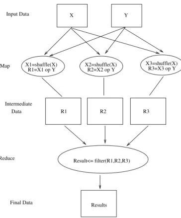
As mentioned, several computations for the p-values must be performed on random shuffles of the initial data. This computation cannot be performed on standard equipment. However, the problem can be run in parallel because the computation can be slice along many dimen-sions (neuroimaging, genetic or permutations). For the case in which the parallelization is done with respect to permutation, each worker will take the same initial data, shuffle it and perform the regression between the 2 sets of data (X, Y)to obtain the correlation between them. The regression from computational point of view represents a series of matrix op-erations, having as result a matrix. All these operations can be simply considered as the job of a mapper if we parallelize the application with the MapReduce programming model. Hence each mapper will perform a regression and will generate as the intermediate output a matrix. The final step, which would be the reducer, must perform a filtering on these val-ues. Therefore the reducer will take all intermediate data, merge them and select the values within a threshold interval. An example of parallelizing this application with respect to the MapReduce model is shown in Figure 7, with 3 mappers and 1 reducer. B shuffles must
be performed, thus the maximum parallelization factor for the map phase is B with respect to the parallelization according to the permutations. The reducer parallelization is not so direct. Basically we can launch more reducers that performs filters on intermediate data, in parallel, but all results should be combine to a unique one. We propose an iterative reduce phase and this will be detailed in section 6.
Result<= filter(R1,R2,R3) R1 R2 R3 X Y Results Intermediate Data Reduce Map Input Data Final Data R1=X1 op Y R2=X2 op Y R3=X3 op Y X3=shuffle(X) X2=shuffle(X) X1=shuffle(X)
Figure 7: MapReduce Example of the neuroimaging and genetic application
4
Contribution I: A DFS for Azure Clouds
This contribution proposes to exploit the data locality principle in public clouds by provid-ing a distributed file system (DFS) that will be run in the computation nodes. This section presents the challenges and the advantages to deploy the DFS in a public cloud. We first present the motivation and then introduce a distributed file system, BlobSeer [29, 30] which has proven to be highly efficient in cloud environments [31]. Finally we detail the enhance-ments developed for this system in order to meet the specific needs of Azure Cloud, along with the benefits obtained from this.
4.1 Motivation
The public clouds like Azure [7, 17] or Amazon EC2 (Elastic Compute Cloud) [2] offer stor-age services like Azure Blobs [15] for Azure or S3 [2, 33] for Amazon. These type of storstor-ages made up of data nodes are in remote locations with respect to the computation nodes. An existing API based on HTTP protocol permits any application, executed on a cloud
com-putation node or outside the cloud, to perform data operations (put/get). The benefits of using these storage systems are data security [12], easy access from anywhere and reliabil-ity [16, 22]. However, when it comes to data-intensive applications, like some of the scientific ones [25, 28, 33], the distance between computation nodes and data nodes affects the perfor-mance. Both Azure and Amazon offer the possibility to select the data centers in which data will be placed and this allows users to place the computation in the same center. However, the overall performance can be increased by moving data closer, in the same racks or perhaps on the same node.
The idea that we propose is to exploit the data locality principle by having the data and the computation in the same nodes of a public cloud. This approach trades data-availability with efficiency, a good tradeoff for scientific applications that are executed in the cloud, since the data, most often private, is not accessed by the general public. To our knowledge there are no DFSs that can be deployed in the computation nodes of public clouds like Azure. Our contribution fills this gap, offering an efficient solution for data-intensive applications. Each virtual machine (node), in both Azure and Amazon clouds, has a local storage space varying from 160GB up to 2TB. This local storage can be used with no additional cost, but the major drawbacks are the fact that it is not persistent (in case of failures all data on it is lost) and is not accessible to the other nodes. Our solution overcomes these limitations and exploits these resources efficiently. It consists of a distributed file system that is deployed on all computational nodes and offers to the application running in each node the same view of a unique, shared file system. The DFS uses the local space on each node to store the data and offers the possibility to all nodes to access data from any other nodes. By placing the data on the local storage of the nodes, the data is as close as possible to the computation, thus applying the principle of data locality. Fault tolerance is addressed through replication: having several replicas ensure that even in case a node fails, the remaining nodes can still retrieve the remaining copies of the data. In addition to efficiency of data manipulation, another advantage relates to the cost. By using a DFS instead of the storage offered by cloud providers, the cost for storage and for the bandwidth traffic are eliminated. The contribution is a general solution that can be applied for any problem.
4.2 BlobSeer
BlobSeer [29] is a distributed file system that combines a set of principles in order to sustain the manipulation of large binary objects (BLOBs). It is centered around the idea of lever-aging versioning for concurrent access to BLOBs in order to efficiently exploit data-level parallelism and sustain a high throughput despite massively parallel data access. Version-ing enables efficient management for data-intensive applications by generatVersion-ing new BLOB snapshots in order to avoid inconsistency even in the case of concurrent read/writes. Such snapshots are performed atomically, simplifying the application development. In order to sustain a high throughput, which is highly needed for such applications, the Input/Output operations are done asynchronously.
A BLOB is composed of a sequence of chunks, using additional metadata to map subse-quences of chunks, identified by offset and size, to the corresponding BLOB. Since such an object can have large sizes it would be inefficient and sometimes impossible to store it en-tirely in one place. Hence, the chunks are stripped across the data nodes, allowing parallel
writes/reads. Their size has a major impact on the overall performance of the DFS and of the application that uses it. It should be chosen based on an analysis of the data access patterns and on simulations on the infrastructure on which it will be deployed. There is a tradeoff between the increase parallelism obtained from splitting the data for the computation into smaller work units and the costs of scheduling, initializing and synchronizing these work units in a distributed fashion. If the chunk size is too small, then computation nodes will need to fetch data from multiple chunks, making techniques such as scheduling the com-putation close to the data less efficient and having to pay for the communication overhead. On the other hand, selecting a chunk size that is too large may force multiple work units to access the same data chunks simultaneously, which limits the benefits of data distribution. Fault tolerance is achieved through replication. Each chunk will be replicated on several data nodes in order to ensure availability in case of failures. Replication is also used for the metadata in order ensure availability.
BlobSeer is composed of several types of distributed intercommunicating entities. Figure 8 illustrates these entities and the interconnections between them. Clients, which in our case are the data-intensive applications, create, read, write and append data to/from BLOBs. The DFS supports a large number of concurrent clients which is mandatory in large scale pro-cessing. Data (storage) providers are the entities responsible to physically store the chunks. The Provider manager keeps information about the available space on the storage providers and schedules the placement of the incoming chunks. Metadata providers are responsible for storing the metadata that allows identifying the chunks that compose a snapshot version. The Version manager is in charge of the new snapshot version numbers for writes and ap-pends and for publishing these snapshots for readers. It is done so as to offer the illusion of instant snapshot generation and to guaranty consistency.
Figure 8: BlobSeer Architecture [29] 4.3 A-BlobSeer
Our contribution further refferd as A-BlobSeer, extends BlobSeer in order to create a DFS de-ployable on the computational nodes of a public cloud. The BlobSeer DFS has been adapted and augmented to meet the specific properties of the Azure cloud. By adapting and improv-ing it, the new system offers all its basic properties and gains the features of the Azure cloud: automatic deployment, recovery of failed nodes, runtime scalability and privacy. Any type
of application like scientific applications as the one discussed in section 3 or commercial applications, can benefit from this contribution. The system offers the necessary means to combine all local storages of worker roles into an unique and uniform file system that can be used to communicate and to pass data between workers. In the same time, data manipu-lation is enhanced due to data locality.
For deploying BlobSeer in the worker roles of Azure, a new entity, which will be called
Initiator was created, that permits the implementation of the proposed idea. Two major
dif-ficulties were encountered. The first one is specific to Azure roles (e.g. worker roles) and consists in the fact that from the point of view of the cloud, the roles are identical [17]. By identical nodes, Microsoft means the fact that all worker role instances will execute the same code. Hence the difficulty is given by the fact that we have to run/start the different entities of BlobSeer (virtual manager, provider manager, metadata providers and data providers) in different instances. Therefore, the Initiator, which is an agent that will run in each role, must make a distinction between instances in order to decide on which machine to start each BlobSeer entity. The second challenge comes from the transparency of clouds. A com-mon assumption in public clouds is that the application will use the default communication mechanisms (e.g. Azure Queues or Amazons Simple Queue Service), so they wont need the IPs of the virtual machines. BlobSeer uses RPC (remote procedures calls - the method through which a process can execute a procedure/function in another address space) in or-der to communicate and to transmit data between entities. Because of this communication model, the Initiator must provide the configuration file with the addresses of all entities to each entity when this is started.
The Initiator is configured to be the first process started and executed when a virtual ma-chine is started. It will access a special service provided by the cloud to ask for metadata about all instances, like IPs, ID etc.. Based on this information this agent is able to take the necessary decision in order to start the DFS. The decision mechanism was designed to al-low customized policies for the DFS and for the application. The Initiator will create the configuration file for BlobSeer, and based on the ID of the virtual machine, it will start the appropriate entity on the local machine. It also takes into account how many entities of each type were specified in the policy. The policy also permits to specify if some nodes will be used just for running the application or just to run specific entities of BlobSeer. If specified, the Initiator is able to start different applications on each machine, which is a new feature that is not supported by default in Azure. Figure 9 offers an overview of the processes that are started in a virtual machine. Even if the policy allows precise customization, the whole process is automated and the user does not need to know any internal details about Azure. A simple example of such a policy would be to start both the application and the entities of BlobSeer on all machines. For BlobSeer, the policy can specify 1 virtual manager, 1 provider manager and a ratio between metadata providers and data providers of 15. Such a policy will permit to restore a virtual machine in case of a failure, and to restart on it the application and the entity of the DFS which was running before the failure. Another property that the overall system presents is the automatic scaling at runtime: for example by adding more computational nodes, the Initiator agent on that machine will assign the role based on the same policy and so the node can be integrated in the computation. The autonomic properties of the A-BlobSeer system are described in section 4.4.
Interface) in order to communicate with the DFS. This API provides simple methods to ma-nipulate data (read, write, append etc.) in a transparent manner. As mentioned previously, BlobSeer uses RPC in order to communicate between its entities. The API that we have con-structed, performs the necessary calls to the appropriate entities, in order to execute each function that is exposed to the application. Through this interface the application that runs in the cloud becomes the client of the DFS as presented in figure 8.
Application BS API BS entity local disk Initiator
Figure 9: A-BlobSeer internal schema on a single node
The contribution of porting a DFS in the cloud is schematized in Figure 10. The A-BlobSeer approach will use the local space of the machines and expose it to the application as a unique and uniform file system. By taking advantage of the properties of the BlobSeer file system, this approach can sustain large number of concurrent clients both for reads and writes while providing efficiency and consistency of the data. This approach allows to take full advantage of the data locality principle even in public clouds, since data is brought as close as possi-ble to the computation. The approach successfully combines the principle of data locality with the computation power of public clouds through the means of a distributed file system adapted for this specific infrastructure.
App.
BS API
Worker
Instance
App.
BS API
Worker
Instance
App.
BS API
Worker
Instance
Storage
Local
Storage
Local
Storage
Local
A−BlobSeer
...
...
4.4 Autonomic properties
An important feature of the large scale systems is their support for autonomic properties in addition to their constant seeking for efficiency and performance. Considering their large scale, manual intervention to adjust, configure or protect them, cannot be applied. Out of the 4 major self* properties:
Self-configuration: the system follows high level policies
Self-optimization: the system seeks to improve their own performances Self-healing: the system detects, diagnoses and repairs problems Self-protection: the system defends against attacks and failures
defined by Kephart et al [27] for autonomic computing, A-BlobSeer provides two and it is designed such that it can be further improved to fulfill all of them.
Self configuration. It refers to the ability of a system to follow policies by automatically adjusting itself to them. As previously mentioned, the Initiator component follows a policy in order to initialize and start A-BlobSeer. It performs the needed configuration in an auto-matic fashion, complying with the customized rules in order to launch the enviroment. The system takes full advantage of the tools offered by the Azure cloud, which allow the appli-cation to be deployed automatically on all computational nodes. An archive containing the application is copied an launched on all machines. In our case, the Initiator will be the entity launched and along with it, all necessary components (executable files for the DFS, special libraries and the application/applications) will be moved on each virtual machine. Hence, the Initiator will be able to finalize the deployment step and continue with the configuration and finally with the launching of the A-BlobSeer processes.
Self configuring systems must not only behave autonomously during deployment, but also during the execution. A-BlobSeer exposes this property also while recovering from crashes. When a node fails, the Azure cloud re-deploys the previously mentioned archive on a new node. The Initiator will be launched on this new machine and will restore both the failed entity of the DFS and the application, by performing the initial configuration and by finding out what was the task of the failed instance. In a similar manner, the system is able to scale during runtime. Taking advantage of the feature offered by Azure, to ask for more or less compute nodes, A-BlobSeer is able to perform the demanded scaling.
In the case of scaling up, the new machine that is added to the system will be integrated into the A-BlobSeer environment by the Initiator, which will create the initial configuration for BlobSeer and will start a data provider and will launch the application according to the policy. Currently the Initiator component is designed to launch any type of BlobSeer entity, based on the policy, but BlobSeer supports only the adding of new data providers. With the future releases that will allow other entities to be added at runtime, the A-BlobSeer envi-ronment will be able to provide all its potential. In order to scale down, we make the same assumption as the underlying DFS: that the replication number of the data on the machine to be shut down is grater then one. If this assumption is violated, data losses can appear. In order to deal with data losses during scaling down or at the moment when the system is explicitly shut down, a self protection mechanism was design and it is described bellow.
Self protection. It is the ability of the system to automatically defend against malicious attacks or cascading failures. In the case of cloud computing, the system is protected by malicious attacks because it is a closed system in a secured environment [12]. On the other hand we have identified two case in which failures can affect the system (scaling down, shut down request). DFSs use data replication in order to prevent data losses when failures happen. Multiple copies of data are created, on different machines which will provide, with a certain confidence level, data availability. The idea that we proposed was to use the local storage of each machine to store the data, but when the user wants to shut down the system, all machines are destroyed so all data is lost no mater how big the replication number was. To address these problems, a self protection mechanism was designed. One or more agents, that run in the virtual machines backup all data from the local DFS into the persistent stor-age offered by the cloud, which in our case are the Azure Blobs. In order not to affect the performance of the application, the agents can be customized to run with a very low priority or just in the moments of inactivity of the main components (BlobSeer entities, application). Basically this agent will be a BlobSeer client that will use the API to copy the data into the remote storage. Since this large movement of data does not belong to the main computation flow, it will not affect the efficiency of the computation. By making backups of the data into a remote storage, no data will be lost when the system is turned off or when a node with data that had one as replication number is closed. In addition, a similar agent is design to do the opposite operation when the system is started. It will be launched by the Initiator component and will restore the system to the state previous to shut down (or a specified state). Hence, the A-BlobSeer will be able to recover even in case of major/total failures or requested shutdowns.
5
Contribution II: MapReduce in Azure
This section presents the challenges and the advantages of the MapReduce programming model in Azure clouds. Our proposed environment combines the strength of this parallel model with the efficiency of the previously presented contribution. The solution called A-BMR uses A-BlobSeer as a storage backend for the MapReduce environment destined for data-intensive applications
5.1 Context
The 2 PaaS programming models presented in section 2.2, Azure roles and MapReduce are not exclusive. As it will be shown, it is possible to deploy a MapReduce environment, which combines the properties of both models, in the Azure roles. This open and customizable platform, offers to anyone the possibility to adapt it with respect to the necessities of the application. Since the A-BMR is designed for a public cloud it benefits from all its advan-tages, like on-demand resources scaling, privacy and security. This contribution combines the idea of having a DFS in the computational nodes with the power and simplicity of the MapReduce model, taking advantage in the same time by all features offered by Azure cloud environment. Our major interest are the data-intensive applications and the work focuses on optimizing the data management for the platform. As presented in the previous sections, a run of MapReduce application has 2 read phases (the reading of the initial data by mappers
and the reading of the intermediate data by the reducers) and 2 write phases (the writing of the intermediate data by the mappers and the writing of the final results by the reducers). The data-intensive applications which are executed using this model, have as critical points these phases [25, 31]. By exploiting the idea of moving the data on the computation nodes the data manipulation phases are optimized.
Currently Azure cloud does not permit the deployment of Hadoop, since it does not provide a Java Virtual Machine and is not able to offer all configuration information and permissions in order to execute it. However, Microsoft has announced that they will provided in the future a service based on Hadoop to execute MapReduce applications. Microsoft has its own framework capable to execute MapReduce jobs, called Dryad [23]. Dryad is superior to MapReduce from the point of view of the workflows that can be executed. While in Hadoop the default flow is the one presented in Figure 7, Dryad can offer a large number of possi-bilities to define the flow of data between instances. The major disadvantage is the fact that currently Dryad can be executed just in Microsoft High Performance clusters and cannot be run in clouds. Hence, at this point there is nothing provided for the MapReduce pro-gramming model or for data-intensive applications by Microsoft and this represents another motivation for our work.
Gunarathne et al [20] have constructed a MapReduce framework called AMR (Azure MapRe-duce) for the Azure cloud, which will be detailed below. They are using Azure Blobs as storage backend for their platform, which does not benefit from data locality principle as A-BlobSeer proposes. Our framework, A-BMR, uses A-BlobSeer in order to exploit the avail-able local storage space for a more efficient data manipulation and uses a simpler commu-nication schema for the coordination among entities. Unlike Hadoop, our system is able to recover the failed nodes and offers runtime scalability.
5.2 AMR
AzureMapReduce (AMR) [20] is a distributed decentralized MapReduce runtime, devel-oped for Azure cloud infrastructure. By using the public cloud infrastructure, AMR takes advantage of cloud features like scalability and high availability. In addition, the distributed nature of these services are guaranteed by the cloud provider to avoid single point of failures, bandwidth bottlenecks and management overhead [20]. The AMR implementation uses the Azure storages as follows: Azure Queues are used for map and reduce task scheduling, Azure BLOBs for storing input, output and intermediate data, Azure Tables for metadata storage and the computational worker roles for running the tasks. In the case of Google MapReduce [19] and Hadoop [37] there exists a central master node in charge with control-ling the work flow, for which failures are assumed to be rare. Its task is to monitor the com-pletion of the jobs and handle the task assignments. AMR implies a decentralized control model with no central control node, thus avoiding possible single point of failures. It uses global queues for scheduling and the tables for metadata storing. Another property that is inherited from Azure environment is the dynamic scalability up or down of the computing instances at runtime.
Figure 11: Azure Map Reduce architecture [20]
Figure 11 presents the AMR architecture. The client is responsible for submitting the map and reduce task to the system by providing the needed data for computing instances. The information manipulated by the client are the addresses of the initial data, the address loca-tions in which intermediate data can be stored and where the final data should be placed. In addition, the client is responsible to create the Azure tables for the metadata needed by the framework and to diffused their addresses. The messages sent by the client towards mappers and reducers through the queues, contain the addresses of the table locations cor-responding to this job and the job description.
The map instances are run in the worker roles provided by Azure. They represent a pool of workers that wait for messages from the client which would assign them jobs. They will read the metadata of that task from the corresponding Azure tables and based on this, they will download the initial data from Azure BLOBs. They will process it and upload the intermediate data back to Azure BLOBs. In order to complete the task they will write the metadata about the intermediate results into Azure tables, from where the reducers can retrieve it.
The reduce instances are similar to the mappers. They are a pool of workers that wait for tasks to be assign to them. Once a job description is retrieved by a reducer from the queue, it will start polling the tables in order to read the metadata about the intermediate data (this is written by mappers when they finish their jobs). When this information is available, the reducer will download the intermediate data from the addresses that are specified by the metadata. The reducer will start the processing when all the map tasks are completed and all the intermediate data destined for this reducer is downloaded. Finally, when the compute phase is finished, they will upload the final result and store in the Azure tables the corresponding metadata about it.
The advantages that the AMR framework presents are decentralized control, scalability and fault tolerance. However, the authors are mentioning the low performances of the storage layer on which their platform is constructed and they state that they are searching for more
efficient ways to perform data transfers [20]. Our idea to move the data in the computation nodes provides a solution for this problem, solving the inefficiency of data manipulation. The A-BMR platform that we have developed, and that will be detailed in the next sub-section, provides an answer to this problem by applying the A-BlobSeer solution that we have proposed. In addition to this, our solution proposes a simpler communication schema for performing the scheduling and for metadata management, eliminating the need to use Azure tables.
5.3 A-BMR
A-BlobSeerMapReduce (A-BMR) platform is a decentralized framework design for Azure clouds, which is optimized for data-intensive applications. The design decisions had to con-sidered the fact that cloud environments are more predisposed to failures than for example computing in clusters. Hence, fault tolerance was carefully considered and in order to ob-tain this property for the system, a platform with no single point of failure was constructed. Unlike AMR, our solution exploits data locality by using A-BlobSeer as a DFS deployed in the computational nodes. Data transfer, protection and confidentiality are enhanced by tak-ing benefit from the fact that the local storage of the compute instances is used for data, instead of a remote storage. Our solution uses only Azure queues for scheduling, since there is no need to interact with Azure tables for metadata management as in the case of AMR. The queues are a reliable, scalable service design for small, short-lived transient messages adequated for job assigments. On the other hand, Azure Tables do not guarantee immediate availability of data, but rather guarantee eventual availability. From the computational point of view, the amount of time until data becomes available is a lost time (the workers are idle). Our system uses the metadata management provided by BlobSeer and allows us to send just small messages between entities, eliminating in this way the need to store additional information in Azure tables.
Figure 12 presents the architecture of our system. The client is an Azure Web Role through which the user can specify the parameters of the job he/she wants to submit. Based on this specifications, the appropriate scheduling messages for mappers and for reducers, are cre-ated and enqueued in the corresponding queues. The scheduling messages that are trans-mitted towards mappers or reducers are small, containing the ID of the mapper/reducer and some small information about the way data can be retrieved from A-BlobSeer. This in-formation contains the blob ID, the size of data and the offset. As in the case of the other MapReduce frameworks like Hadoop or AMR, the initial data is supposed to be present in the storage system when the application is launched. Since the underlying DFS has an efficient striping policy, the influence of the way the initial data is written into the file sys-tem has minimum impact on the overall performance. This data can be simply uploaded in A-BlobSeer through a web interface provided by the client.
A-BlobSeeris used as a unique and uniform storage backend for the A-BMR platform. The reading of initial data and of the intermediate data and the writing of intermediate data and of the final data is performed in the local storage space of the computational nodes. This local storage is exposed as a whole for the application. A-BlobSeer supports concurrent read and writes, guaranteeing in the same time the consistency of the data. The only information needed by an application to access through the BS-API the data is the ID of the blob in which the data resides , the size of the data and the offset. By using the local storage space
which is available in the compute instance machines, not only that the efficiency of the data manipulation is increased, but also the cost to run a MapReduce application is decreased. The execution costs decrease because the local space is free, while for the remote storage we have to pay both for the actual storing and for the bandwidth to access it.
The mappers are deployed in Azure worker roles. Based on the parameters specified for the A-BlobSeer, a pool of mappers is created. They are regularly polling the scheduling queue in order to retrieve the messages with the job description submitted by the client. They will start reading the initial data through the BS-API provided by A-Blobseer and will run the job. After the processing phase they are writing the data in the DFS through the same API, and they create small messages for reducers containing the information about the intermediate data, which will be enqueued in the synchronization queue. Finally they will return to the pool of mappers waiting for new tasks.
The reducers are similar with the mappers, being also deployed in Azure worker roles and based on the customization parameters, a pool of reducers is created at deployment time. The reducers first poll the queue through which the client submits the jobs, and when a task is being assigned, the reducer which becomes in charge of it will start listening to the synchronization queue. It waits until at least one message is send from the mappers towards the reducer. It will dequeue the message and fetched the intermediate data. The data will be processed and then the reducer will move to the next intermediate data, which is destined for it and so on. Unlike AMR, our framework starts to process intermediate data as soon as some data is available in order not to keep idle the reducer until all mappers have finished. When all data was processed, the final result will be written in the A-BlobSeer. However, the framework can also be configured to wait for the completion of all map tasks before starting a reducer job. This feature is provided because there exists applications which require all data present in the reducers before starting the processing.
The queues are used as a scheduling mechanism by A-BMR. The Azure queues guarantee that a submitted message will not be lost, and will be eventually executed by a worker. Thus by implying them in the scheduling process our framework gain fault tolerance in case of unexpected crashes. There are 3 queues in A-BMR: the Map Scheduling Queue is used by the client to submit jobs towards mappers, the Reduce Scheduling Queue is used by the client to submit jobs towards reducer and the Syncronization Queue is used by the mappers to informed the reducers that intermediate data is available for processing.
00000000000 00000000000 11111111111 11111111111 0000000000 0000000000 0000000000 1111111111 1111111111 1111111111 0000000000 0000000000 0000000000 1111111111 1111111111 1111111111 00000000000 00000000000 11111111111 11111111111 M M M Syncronization Queue R R Client
Map Scheduling Queue
Reduce Scheduling Queue
...
...
...
... ... Dequeue message Upload data Download data Enqueue message A−BlobSeer A−BlobSeer A−BlobSeer New componentsFigure 12: A-BMR architecture
Our framework takes advantage of the properties offered by Azure and by the DFS solution that we proposed (A-BlobSeer). A-BMR is a decentralized MapReduce framework with an optimized data manipulation layer which exploits data locality by using the free local stor-age present in computation nodes instead of the remote storstor-age. It is a scalable framework, having the ability to scale on-demand at runtime and being fault tolerant. As it was de-scribed in the section in which A-BlobSeer was detailed, the Azure environment re-deploys the eventual failed nodes, and the A-BlobSeer environment is able to re-integrate these ma-chines in the computation. Hadoop, which is the reference implementation for MapReduce, does not provide neither runtime scalling nor the node recovery as our system does. Data losses are prevented by the replication mechanisms used by the DFS, while for the tasks (the submitted jobs) we prevent losses through Azure queues. A message in the queue is guarantee by Azure not to be lost. For the read (dequeued) messages that are executed by mappers/reducers the following mechanism prevents losses: a dequeued message is not ac-tually deleted from the queue, being only hidden for a time period. During this amount of time, the mapper/reducer must finish the job and explicitly delete the message. In the even-tuality that the computation node crashes before the job is finished, the message will not be deleted from the queue. Hence, it will reappear and will be executed by another worker. The system benefits from a simple yet efficient scheduling schema, that along with efficient data management layer offered by A-BlobSeer, makes A-BMR a very good solution for executing data-intensive application in public clouds.
6
Contribution III: Iterative MapReduce
MapReduce programming model is a simple, yet powerful model adequate for acyclic algo-rithms. However, there are several types of data-intensive applications that require several rounds of processing on the data in order to generate the final result. A possible approach is to create a pipeline of MapReduce, but this approach has proven to be less efficient than a
![Figure 1: Cloud layers [30]](https://thumb-eu.123doks.com/thumbv2/123doknet/5559418.133167/5.918.310.592.164.324/figure-cloud-layers.webp)
![Figure 2: MapReduce data flow with multiple reduce tasks [37]](https://thumb-eu.123doks.com/thumbv2/123doknet/5559418.133167/10.918.204.741.281.558/figure-mapreduce-data-flow-multiple-reduce-tasks.webp)
![Figure 3: Hadoop Architecture [37]](https://thumb-eu.123doks.com/thumbv2/123doknet/5559418.133167/11.918.232.714.331.692/figure-hadoop-architecture.webp)
![Figure 4: HDFS architecture [37]](https://thumb-eu.123doks.com/thumbv2/123doknet/5559418.133167/12.918.231.720.416.715/figure-hdfs-architecture.webp)
![Figure 5: Azure computation model [17]](https://thumb-eu.123doks.com/thumbv2/123doknet/5559418.133167/13.918.256.694.395.648/figure-azure-computation-model.webp)
![Figure 6: Azure storage model [17]](https://thumb-eu.123doks.com/thumbv2/123doknet/5559418.133167/14.918.266.686.173.437/figure-azure-storage-model.webp)
![Figure 8: BlobSeer Architecture [29]](https://thumb-eu.123doks.com/thumbv2/123doknet/5559418.133167/19.918.326.579.709.909/figure-blobseer-architecture.webp)

![Figure 11: Azure Map Reduce architecture [20]](https://thumb-eu.123doks.com/thumbv2/123doknet/5559418.133167/25.918.214.680.162.503/figure-azure-map-reduce-architecture.webp)
