HAL Id: hal-01487055
https://hal.archives-ouvertes.fr/hal-01487055
Submitted on 10 Mar 2017
HAL is a multi-disciplinary open access archive for the deposit and dissemination of sci-entific research documents, whether they are pub-lished or not. The documents may come from teaching and research institutions in France or abroad, or from public or private research centers.
L’archive ouverte pluridisciplinaire HAL, est destinée au dépôt et à la diffusion de documents scientifiques de niveau recherche, publiés ou non, émanant des établissements d’enseignement et de recherche français ou étrangers, des laboratoires publics ou privés.
Continuous Requirements Engineering Using Model
Federation
Fahad Rafique Golra, Antoine Beugnard, Fabien Dagnat, Sylvain Guerin,
Christophe Guychard
To cite this version:
Fahad Rafique Golra, Antoine Beugnard, Fabien Dagnat, Sylvain Guerin, Christophe Guychard. Con-tinuous Requirements Engineering Using Model Federation. RE 2016 : 24th IEEE International Re-quirements Engineering Conference, Sep 2016, Beijing, China. pp.347 - 352, �10.1109/RE.2016.42�. �hal-01487055�
Continuous Requirements Engineering using
Model Federation
Fahad R. Golra, Antoine Beugnard, Fabien Dagnat
IRISA / T´el´ecom Bretagne Brest, France
Email: [email protected]
Sylvain Guerin, Christophe Guychard
Openflexo Brest, France
Email: [email protected]
Abstract—Researchers in software engineering have been striv-ing to produce new methods to improve the quality of devel-opment methodologies to consequently produce quality prod-ucts. Proposition of iterative and evolutionary approaches was triggered by the realization that requirements engineering is not confined to the initial phases of software development only. With this shift of perspective, requirements engineering has become more or less a continuous process in software development lifecycles. We believe that existing requirements engineering approaches and associated tooling leave a room for improvement in putting ’continuity’ into practice. A con-tinuous requirements engineering methodology needs to take into account different concerns of all the stakeholders involved in the process. Approaches like KAOS bring the multi-view nature of requirements modeling in focus by using different views for goal, responsibility, object and operation modeling. We argue that a multi-view approach, maintaining a dynamic link between the requirement models and multiple sources of requirements, can offer a better support for continuous requirements engineering methodology. In this paper, we ex-pand on this argument and present the early findings with the associated in progress tooling support.
1. Introduction
Information systems are increasingly becoming com-plex, consequently the requirements engineering method-ologies need to be more systematic and efficient. In order to deal with these complexities, requirements engineering methodologies exploit the concept of abstraction. Early sys-tem requirements specify the objectives of stakeholders at a high level of abstraction, which are then refined to a desired level of detail. Use of goal models for the elicitation and analysis of early requirements has been studied in detail e.g. KAOS [1] or Tropos/i* [2]. These approaches refine the requirements to a fine-grained level and map them to system models. Different approaches map these require-ments to different artifacts of the system under development or its environment through traceability links [3]. These used or produced artifacts adhere to different paradigms. For example, models of human behavior, system models, hardware models, etc. do not follow OMG’s MetaObject
Facility (MOF) paradigm like most other software models. Furthermore, requirements engineering is a complex pro-cess dealing with different views for various stakeholders. For example KAOS specifications are presented using four models i.e. goal, responsibility, object and operation mod-els [1]. This calls for a requirements modeling approach that can handle different paradigms and multiple views of a requirements management system.
The development of an embedded system like train door operations is a good example where requirements need to take hardware-driven software synthesis into account. Apart from hardware models like electric circuits, sensor models, etc., requirements need to deal with other models like system of systems model, human behavior models, etc. Another important concern for software development is to manage the development costs of a product. Different approaches try to relate implementation costs to requirements, quite early in the software development process. This might be done, for example to prioritize requirements according to a cost-value approach [4]. For such techniques, they need to have continuous synchronization between the requirements and a cost analysis document (e.g. an excel spreadsheet). Contrary to the models usually developed by software engineers, these models do not conform to MOF and thus it is hard to map their features to the requirement models used for software development. Many other examples (e.g. planning, configuration management, etc.) exist where software devel-opment teams come across the need of a multi paradigm and multi-view requirements modeling methodology that can continuously synchronize these different models.
Requirements engineering is not an initial phase of system development anymore, it continues all along the development lifecycle. So requirement models need to be connected to different artifacts, even if they are produced late in the development lifecycle to allow their continuous improvement. In this article we propose an approach that links together models from different paradigms to produce new views of the system. These dynamic links between models are maintained, so that requirements remain con-nected to these models (information resources). Whenever an information resource updates, the requirements of the system can be updated (manually or automatically) accord-ingly. We call this continuous requirements engineering,
because our methodology enables the continuous update of requirements using all the linked models throughout the system development lifecycle. The contribution of this paper is the use of model federation as a technical basis for re-quirements management. Model federation is a methodology that allows connecting models of different paradigms [5]. In the context of requirements engineering, it furnishes the possibility to create and maintain dynamic links between the requirement models and other artifacts (models of varying paradigms), used all along the development process.
The rest of this paper is organized as follows. First, we present model federation in Section 2. Then, in Section 3, we explain the proposed approach for requirements engi-neering using model federation. Then, Section 4 discusses the literature review for different approaches that are used for linking requirements to the information resources and the system. Finally, we conclude this paper in Section 5.
2. Model Federation
Requirements engineering serves as an interface between a system and its environment. It focuses on gathering the in-formation (domain models) from the environment by collect-ing the requirements for the system to be developed. In such a scenario, the artifacts and processes of requirements engi-neering are tightly related to both the system under devel-opment and its environment. In the context of requirements engineering, sharing information between these processes and artifacts is handled through different activities, ranging from manual (e.g. feasibility study, requirements elicitation techniques, etc.) to semi-automatic (e.g. requirements vali-dation, requirements management, etc.). These artifacts and other information resources used or produced by these activ-ities often share cross-cutting concerns. These cross-cutting concerns are captured through traceability links between them, which allow to traverse from initial phase artifacts to later ones (forward traceability) or from later phase artifacts to initial ones (backward traceability) [3]. In this article we propose to use model federation to connect these artifacts and information resources to allow continuous and unin-terrupted requirements engineering process that offers the technical basis to implement constant improvement method-ologies. But before going into the details of our proposal, we describe the main concepts of model federation.
Model federation is an approach that provides the means to integrate multiple models conforming to different paradigms [5]. A lot of work has been carried out to integrate models from the same paradigm to get a differ-ent views for each stakeholder. This can be accomplished through approaches like model merging, profiling or ex-tension mechanisms provided by UML [6], model weaving with KerMeta [7], or other model composition approaches. However, it becomes difficult, when models are conforming to different paradigms [8]. Model federation approach is developed as a possible response to a request for proposal (RFP) by OMG [9]. This RFP requests submissions for a standard addressing, ”federation of information across different representations, levels of abstraction, communities,
Conceptual Space Technological Space A
B A
Legend:
Model Model element(technological space)
Technological connector
Model slot Flexo concept (remote)
Flexo concept (local) Design Space Diagram 1 A B Design Technological Space B Dynamic link
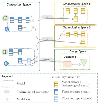
Figure 1. Mapping between concepts in modeling spaces
organizations, viewpoints, and authorities”. Thus model federation allows the integration of heterogeneous models to develop new cross-concern viewpoints/models or to syn-chronize the models used for designing a system. Contrary to other techniques that transform, merge or compose the models in a common paradigm, we propose to keep models in their respective paradigms to avoid redundancies. Hence, we introduce multiple modeling spaces i.e. conceptual, tech-nological and design space, as shown in Figure 1.
The different modeling spaces of our approach serve together for the development of a complex system. The conceptual space is where new models or views are de-veloped by federating the concepts from already existing models. These federated models are called virtual models. As virtual models reuse the concepts from various models conforming to different paradigms, the conceptual space is surrounded by multiple technological spaces. Each of these technological spaces is a collection of models adhering to a common paradigm which gives a common ground for their interpretation. Usually, the technological models are already developed to serve some specific concerns. They might even belong to some different system. Finally, a design space is a specific kind of technological space that serves for diagrammatic representations of the virtual models, using the same interaction mechanism.
Model federation is realized through virtual models to develop new concepts. We have developed a generic mod-eling language to define virtual models in the conceptual space. They are developed using features that can either be specifically defined for virtual models or by reusing elements of models from any of the existing technological spaces. Each of these features, serving as a building block for a virtual model, is called a flexo concept. A virtual
model is responsible for managing the lifecycle of all the flexo concepts that it contains. While virtual models follow the formalisms defined by our methodology, technological models follow their own paradigm depending on their spe-cific technological space. A virtual model can not access the elements of a technological model, unless it can interpret the formalisms used in its technical space. This is done using a connection between the technological space and the conceptual space, realized as technological connectors. These connectors allow access for reading, writing and syn-chronizing the information between the virtual models and the technological models. Once developed, a virtual model can be serialized back into a new or existing technological space for further development.
A virtual model is composed of flexo concepts. Some of these flexo concepts are defined specifically for the develop-ment of a virtual model, we call them local flexo concepts. Virtual models can also use certain elements from connected technological models. One way is to create a dynamic link between these local flexo concepts and the modeling elements of technological models. Virtual model A shown in Figure 1 uses two dynamic links; one to the model in technological space A and the other to the one in technological space B. The second way of using model elements from technological spaces is to translate them into flexo concepts. A remote flexo concept of a virtual model is a translated modeling element from a linked technological space, serving as a ’local proxy’. Virtual model B shown in Figure 1 contains a remote flexo con-cept, which is a local ’proxy’ of a model element from technological space B. In both these techniques, the link between the flexo concept and the technological model is bi-directional and is maintained to synchronize any changes. A virtual model in the conceptual space can be updated when a corresponding technological model evolves and conversely, a technological model can also be updated, once the corresponding virtual model is modified. As the information is shared between multiple models, it might be accessed and modified by multiple stakeholders at the same time. We do not enforce any specific consistency model in this case, we rather give this flexibility to the designers to implement any consistency model that suits their specific application. We provide a notification system that notifies the designer/stakeholder whenever a corresponding model is updated. One can choose for automatic synchronization of models, but then human intervention would be needed for resolving conflicts. Design space is a specific technological space provided by our methodology for diagrammatic repre-sentations of the virtual models. A technological connector between conceptual space and design space allows linking the flexo concepts to their graphic representations. These bi-directional links are maintained, so a virtual model can be edited either from design space or the conceptual space. The technological connectors allow models in concep-tual space to access the models of technological spaces, however the actual dynamic link between these models is re-alized using model slots. Our approach of model federation can be explained through the analogy of components based
design, where models serve as components, model slots as component interfaces and technological connectors as connectors. Technological connectors allow the creation of a dynamic link between a virtual model and a technological model using model slots. A model slot defines an access point both for a virtual model and a technological model to link them together. It exposes a view on the structural and behavioral contents of the technological model to the virtual model and vice-versa. Once linked to a technological model, a virtual model can read/write to its attributes using roles and execute the actions using edition actions. Roles and editionActions are to a flexo concept, what attributes and methods are to a class, except that roles and editionActions are associated to attributes and methods of a model adhering to an entirely different paradigm.
Taking the example of the requirements specification model for an embedded system, as explained in the intro-duction section, we can connect it to cost analysis spread-sheet1 to prioritize requirements according to a cost-value
approach. In order to realize a cost-value requirements priority model, we need to develop it as a virtual model in the conceptual space. The conceptual space needs to be connected to two technological spaces i.e. MS Excel space for cost analysis spreadsheet and MS Word space for requirements specification document2. Both these
techno-logical connectors are already available through our tool-ing support. Ustool-ing these connectors, we can develop our virtual model with two flexo concepts i.e. Requirement and Priority. Requirement can be implemented as a remote flexo concept, thus making a ’proxy’ for each re-quirements in the virtual model that is dynamically linked to the requirements of the specification document. Priority concept can directly be linked to the cost analysis document to assign a priority value to each requirement. Model slots for these links need to be developed by the modeler to connect these concepts. Even though it is not a good idea to update cost analysis document from this model, for the purpose of explanation we assume that the designer has the possibility to update/modify the cost of each requirement in the cost analysis document from the virtual model, using the edition action setCellValue(). Furthermore, any other com-mon piece of information can be synchronized acom-mong cost-value requirements priority model, requirements specifica-tion document and cost analysis document. The cost-value requirements priority model can be developed using a graph-ical editor of design space, hence editing/synchronizing the flexo concepts in the virtual model.
3. Requirements engineering through model
federation
Each stakeholders involved in the requirements engineer-ing process can have a different view about the system. Each
1. .xlsx files are XML based spreadsheets. We consider all artifacts in software development as models.
2. Different tools like IBM Rational RequisitePro, CaseComplete, Visure requirements etc. share requirements based on MS Word format.
Conceptual Space
Technological Space MS Word
Design Space
MS Word
KAOS
Design
Technological Space KAOS
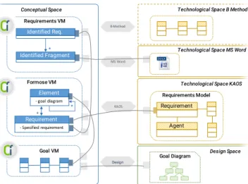
Goal Diagram Requirement Agent Requirements Model Goal VM Identified Req. Requirements VM Identified Fragment* Element - goal diagram Formose VM * Requirement - Specified requirement *
Technological Space B Method
B-Method
Figure 2. Model Federation for Requirements Engineering
view caters a subset of concerns related to the complete software development process. Many of these views are created as different models like requirements specification document, goal models, system models, etc. Requirement model itself has conceptual links (at times expressed as traceability links) to different artifacts produced during the development process (like feasibility reports, minutes of the meetings, design models, code, etc.) and to other informa-tion resources like organizainforma-tional norms, quality standards, government policies, etc. Different artifacts and processes used or produced during the software development lifecycle reinforce the need of a multi-view approach for requirements engineering. Popular requirements engineering approaches, like KAOS, are presented through multiple views i.e. goal, responsibility, object and operation models [1].
As already said, we propose to use model federation as an approach for modeling the requirements, where multiple views/models of the system might not adhere to a single paradigm. In case of KAOS models, their metamodel is defined using MOF. However, other domain models used in software development may not belong to the same paradigm e.g. legacy systems, databases, reports, spreadsheets and other specific domain models like building architecture mod-els, electric circuit diagrams, CAD modmod-els, etc. Many of these models might be needed as information resources to update software requirements. A multi-paradigm modeling approach becomes necessary to cater these needs. Model federation approach, described in Section 2, offers the pos-sibility to integrate models from different paradigms and to create new concepts using virtual models that can use information from them.
Apart from linking the concepts of different models, model federation allows to maintain those dynamic links. This means that all these models used in the requirements engineering process remain connected to the requirements model, hence updating of the specified requirements as soon as the information resources are modified. Model federation is a modular approach that treats each model
as a ’component’ and connects to them using specified interfaces, the model slots. This allows adding new models to the system without the need of re-designing the com-plete system. This modular approach permits connecting more information resources to the requirement specification model even during late stages of software development. So artifacts developed at later phases of the process or in future iterations in case of agile development, can easily be linked with existing requirements. This support for linking new information resources to the requirements and maintaining them for synchronization allows a continuous requirements engineering process all along the software development lifecycle, regardless of its phase and iteration.
Apart from using model federation for continuous elici-tation of requirements through synchronization of informa-tion resources, we propose it for developing new views by federating different models that might not follow the same paradigm. As a proof of concept we have federated the goal-oriented requirements engineering model, KAOS in our methodology. However, we are looking forward to integrate other methodologies in different technological spaces, so that a requirements engineer can use multiple approaches for the requirements engineering process. This is implemented through an abstract model of requirements engineering, Formose virtual model in the conceptual space, as shown in Figure 2. This virtual model is made up of two concepts; element refers to the decomposition of project elements and requirement, which are collected and re-fined for each of those elements. Note that for us, a project element does not mean an element of the system to be developed only, but it can also be a part of the development process, context of the process or the context of the software system. In the current implementation, both Element and Requirement are refined using the KAOS methodology, whose model is available in the technological space KAOS. For the elicitation of requirements from multiple mod-els, those models can be connected through their respec-tive technological spaces. Technological space MS Word allows to connect the Requirements virtual model (VM) to different word documents like feasibility reports, project proposals, minutes of the meetings, etc. for require-ments elicitation. Requirerequire-ments VM allows the identifi-cation of the fragments from the model (word file in this case) that can serve as a source for requirements. These fragments are used to identify the requirements of the system under development. These identified requirements are mapped to the Formose VM for their specification. They are further linked to Goal Virtual Model (VM) for the development of goal oriented requirements model. Finally this goal model is mapped to the design space for its diagrammatic representation. Once all these models are dynamically linked with each other for carrying out the requirements engineering process, they are synchronized between themselves. Resultantly, we are able to modify the requirements model by 1) adding new models to the technological spaces and identifying new requirements from them, 2) modifying the models in the technological spaces and updating the requirements across the system (which
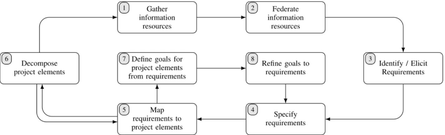
Gather information resources 1 Federate information resources 2 Decompose project elements
6 Define goals for
project elements from requirements 7 Refine goals to requirements 8 Identify / Elicit Requirements 3 Map requirements to project elements 5 Specify requirements 4
Fig. 3. Requirements engineering process with model federation
In order to understand how model federation can be used in the context of requirements engineering, we need to under-stand how it changes the requirements engineering methodol-ogy. Figure 3 explains the activities involved in the proposed methodology. It needs to be noted here that this is a work in progress, so we have not yet covered requirements validation activities in this process. However, adding a technological space for formal validation of requirements is one of the future goals of our methodology (see Technological Space B Method in Figure 2). For now, our methodology is explained through the following activities:
1) Gather information resources: This activity involves the identification of possible information resources that can be used to elicit requirements. They can vary from early information resources like feasibility reports, standards and minutes of the meetings to late informations sources like deployment models, test plans, etc.
2) Federate information resources: Once the information resources are collected they need to be linked with the requirements. This is handled through the model federation approach where requirement models are de-veloped as virtual models in the conceptual space and other models (information resources) are placed in their respective technological spaces.
3) Identify/Elicit requirements: Once the information re-sources are linked with the requirements model, we can identify the requirements from those information resources. For the moment, we have used the techno-logical space for Microsoft word documents to identify multiple fragments for possible requirements. Different documents are used for this purpose like project propos-als, interview transcripts, feasibility reports, etc. 4) Specify requirements: Once the requirements are
iden-tified from multiple information resources, they are specified in the requirements model. In case the require-ments are already specified, they are linked with the information resources for synchronization.
5) Map requirements to project elements: In this activity, the specified requirements are mapped to the project elements. Multiple requirements can be mapped to a
single project element.
6) Decompose project elements: Multiple requirements mapped to a project element describe the expected functionality from that element. This allows the decom-position of the element into sub elements, such that each sub element takes care of a subset of the requirements mapped to its parent element.
7) Define goals for project elements from requirements: All the requirements associated with a project element are considered as goals in this activity. A goal model is developed for each of these goals.
8) Refine goals to requirements: All the goal models are refined to get requirements at the leaves of the goal mod-els. These requirements can be specified in activity 4. These activities are performed according to the control flow described by Figure 3. This is an iterative flow of activities where we see two sub-cycles in the complete iteration; one corresponds to the decomposition of project elements and the other to the refinement of requirements. A single activity, Map requirements to project elements, serves as the entry point for both these cycles. These cycles are often alternating, which describes that the system decomposition occurs in parallel to the refinement of requirements.
Tooling support for our methodology is provided through our open source project initiative, Openflexo [12]. This tool has been developed as a generic collaborative platform for multifaceted modeling using model federation. We have de-veloped technological connectors for different technological spaces like EMF, OWL ontologies, XML/XSD, pdf files, MS office documents for Word, Excel, PowerPoint, etc. These technological connectors allow the use of different models as information resources and can be federated to the requirements model for our continuous requirements engineering approach.
IV. RELATEDWORKS
In an empirical study conducted on traceability, Ramesh and Jarke suggest that traceability links should be strongly typed in order to avoid semantic misinterpretations [13]. They also proposed a traceability meta-model and reference model in this context. There work is focused on the rationale and definition
Figure 3. Requirements engineering process with model federation
is the case of requirements evolution in later stages of the software development lifecycle), 3) modifying the goal oriented requirements model through its diagram in the design space, 4) modifying the requirements directly from the virtual models. In all these cases, the modifications are reflected in other federated models.
In order to understand how model federation can be used in the context of requirements engineering, we need to understand how it changes the requirements engineering methodology. Figure 3 explains the activities involved in the proposed methodology. It needs to be noted here that this is a work in progress, so we have not yet covered requirements validation activities in this process. However, adding a tech-nological space for formal validation of requirements is one of the future goals of our methodology (see Technological Space B Method in Figure 2). For now, our methodology is explained through the following activities:
1) Gather information resources: This activity in-volves the identification of possible information resources that can be used to elicit requirements. They can vary from early information resources like feasibility reports, standards and minutes of the meetings to late informations sources like deploy-ment models, test plans, etc.
2) Federate information resources: Once the informa-tion resources are collected they need to be linked with the requirements. This is handled through the model federation approach where requirement mod-els are developed as virtual modmod-els in the concep-tual space and other models (information resources) are placed in their respective technological spaces. 3) Identify/Elicit requirements: Once the information resources are linked with the requirements model, we can identify the requirements from those infor-mation resources. For the moment, we have used the technological space for MS Word documents to identify multiple fragments for possible require-ments. Different documents are used for this pur-pose like project proposals, interview transcripts, feasibility reports, etc.
4) Specify requirements: Once the requirements are identified from multiple information resources, they are specified in the requirements model. In case the requirements are already specified, they are linked with the information resources for synchronization. 5) Map requirements to project elements: In this ac-tivity, the specified requirements are mapped to the project elements. Multiple requirements can be mapped to a single project element.
6) Decompose project elements: Multiple require-ments mapped to a project element describe the ex-pected functionality from that element. This allows the decomposition of the element into sub elements, such that each sub element takes care of a subset of the requirements mapped to its parent element. 7) Define goals for project elements from
require-ments: All the requirements associated with a project element are considered as goals in this activity. A goal model is developed for each of these goals.
8) Refine goals to requirements: All the goal models are refined to get requirements at the leaves of the goal models. These requirements can be specified in activity 4.
These activities are performed according to the control flow described by Figure 3. This is an iterative flow of activ-ities where we see two sub-cycles in the complete iteration; one corresponds to the decomposition of project elements and the other to the refinement of requirements. A single activity, Map requirements to project elements, serves as the entry point for both these cycles. These cycles are often alternating, which describes that the system decomposition occurs in parallel to the refinement of requirements.
Tooling support for our methodology is provided through our open source project initiative, Openflexo [10]. This tool has been developed as a generic collaborative platform for multifaceted modeling using model federation. We have de-veloped technological connectors for different technological spaces like EMF, OWL ontologies, XML/XSD, pdf files, MS office documents for Word, Excel, PowerPoint, etc. These technological connectors allow the use of different
models as information resources and can be federated to the requirements model for our continuous requirements engineering approach.
4. Related Works
In an empirical study conducted on traceability, Ramesh and Jarke suggest that traceability links should be strongly typed in order to avoid semantic misinterpretations [11]. They also proposed a traceability meta-model and reference model in this context. There work is focused on the rationale and definition of conceptual base for the development of traceability links. Mader et al. advocate the use of traceabil-ity information model as a necessary condition to employ traceability [12]. Dag et al. propose to link requirements to domain models using linguistic engineering approach [13]. On a conceptual level, all these techniques work well to identify which requirements need to be linked with customer wishes (domain problems), however they don’t focus on the technical aspects of how these links should be created and maintained. As a complementary approach on the technical level, we focus on how these links will be maintained and what happens when the customer wishes evolve over time. Apart from customer wishes, we focus on linking requirements to many other models from the domain and from the system itself.
Most of these techniques use bi-directional model trans-formations for creating and maintaining such links. How-ever, these techniques are confined to the MOF paradigm, specified by OMG. Other techniques like KerMeta using aspect weaving for multi-paradigm modeling [7] pose the same problems of conformity to MOF. Most of the existing techniques that allow the development of new views from existing models in the context of multiple paradigms are either bound to MOF or are not modular enough to be used in requirements engineering where new information resources can be linked to the requirements model even late in system development [8]. Model federation is a modular approach that is not confined to MOF for linking different kinds of information resources to the requirements models. As a perspective of this RE Next paper, we are planning to add a technological space for B method that will serve for requirements verification. We will also add technological spaces other than KAOS, so that multiple approaches can be used coherently for requirements engineering in complex system development. Lastly, some industrial use cases are under study to practically validate our claims.
5. Conclusion
Synchronizing the information between different infor-mation resources in requirements engineering poses a hurdle for timely update of requirements. Considering all these information resources as models, we have proposed an ap-proach of model federation that allows information sharing by maintaining a dynamic link between different models. Model federation favors the use of different views of each
stakeholder that can be developed from modeling elements of different models adhering to different paradigms. Devel-opment and maintenance of multiple models in requirements engineering through model federation impacts the require-ments engineering methodology as well. This methodology focuses on continuous requirements engineering activities that are carried out all along the software development lifecycle. For the moment, we have integrated goal oriented requirements engineering approach, KAOS with our core requirements model. But this work in progress is heading towards the integration of technological spaces for other requirements modeling approaches and formal verification, in the context of safety and security.
Acknowledgment
We are thankful to French national agency, Agence Na-tionale de la Recherche (ANR), for funding this research under FORMOSE project ANR-14-CE28-0009.
References
[1] A. van Lamsweerde, “Goal-oriented requirements engineering: a guided tour,” in Fifth IEEE International Symposium on Requirements Engineering, 2001. Proceedings., 2001, pp. 249–262.
[2] P. Bresciani, A. Perini, P. Giorgini, F. Giunchiglia, and J. Mylopoulos, “Tropos: An Agent-Oriented Software Development Methodology,” Autonomous Agents and Multi-Agent Systems, vol. 8, no. 3, pp. 203– 236, 2004.
[3] F. A. C. Pinheiro, “Requirements Traceability,” in Perspectives on Software Requirements. Boston, MA: Springer, 2004, pp. 91–113. [4] J. Karlsson and K. Ryan, “A cost-value approach for prioritizing
requirements,” IEEE Software, vol. 14, no. 5, pp. 67–74, Sep 1997. [5] F. R. Golra, A. Beugnard, F. Dagnat, S. Guerin, and C. Guychard,
“Addressing modularity for heterogeneous multi-model systems using model federation,” in Companion Proceedings of the 15th International Conference on Modularity. ACM, Mar. 2016, pp. 206–211. [6] B. Selic, “A Systematic Approach to Domain-Specific Language
De-sign Using UML,” in 10th IEEE International Symposium on Object and Component-Oriented Real-Time Distributed Computing, 2007. ISORC ’07, May 2007, pp. 2–9.
[7] J.-M. J´ez´equel, B. Combemale, O. Barais, M. Monperrus, and F. Fou-quet, “Mashup of metalanguages and its implementation in the Kermeta language workbench,” Software & Systems Modeling, vol. 14, no. 2, pp. 905–920, 2013.
[8] C. Hardebolle and F. Boulanger, “Exploring Multi-Paradigm Modeling Techniques,” SIMULATION, vol. 85, no. 11-12, pp. 688–708, 2009. [9] OMG. (2011, November) Semantic Information Modeling for
Fed-eration (SIMF) Request For Proposal. http://www.omg.org/public schedule. Needham, MA, USA. Online; accessed: 2016-07-01. [10] Openflexo. (2016) Openflexo project. http://www.openflexo.org.
On-line; accessed: 2016-07-01.
[11] B. Ramesh and M. Jarke, “Toward reference models for requirements traceability,” IEEE Transactions on Software Engineering, vol. 27, no. 1, pp. 58–93, Jan 2001.
[12] P. Mader, O. Gotel, and I. Philippow, “Getting back to basics: Promoting the use of a traceability information model in practice,” in ICSE Workshop on Traceability in Emerging Forms of Software Engineering, 2009., May 2009, pp. 21–25.
[13] J. N. o. Dag, B. Regnell, V. Gervasi, and S. Brinkkemper, “A linguistic-engineering approach to large-scale requirements manage-ment,” IEEE software, vol. 22, no. 1, pp. 32–39, 2005.