Pépite | Étude de l'activité intrinsèque des catalyseurs Fischer-Tropsch à base de cobalt et de fer par des méthodes cinétiques transitoires
187
0
0
Texte intégral
(2) Thèse de Alexandre Antônio Bento Carvalho, Lille 1, 2017. Acknowledgements I would like to begin by expressing my gratitude to Dr. Andrei Khodakov and prof. Nilson Marcilio. I have learned so much in their research group. I am so grateful for their encouragement, patience, interest and help. Their guidance made this PhD a possible and a great work. I also present my sincere thanks to Dr. Vitaly Ordomsky and prof. André Muniz. I would like to express my gratitude to the Programa de Pós-Graduação em Engenharia Química (PPGEQ) of the Federal University of Rio Grande do Sul and to the Unité de Catalyse et Chimie du Solide (UCCS) of Université de Lille 1. As well, I express my gratitude to the CAPES/COFECUB project for my Ph.D. grant. Special thanks to Dr. Mirella Virginie for all the help and support. I express my gratitude to all member of the UCCS and PPGEQ for all help. Special thanks to Olivier Gardoll, Svetlana Hyete, Johann Jezequel, Joelle Turiot, Doris Borges and Patrício Freitas. I present my thanks to Dr. Benoit Legras and Dr. Maya Marynova for all contributions. A special thanks to Yuan Luo for being available all the time during my experiments. Most importantly, for being my friend. A special thanks to my friends Zeinab, Dmitri, Mehdi, Anouschka, Leila, Tong, Ana Sofia, Jin, Nuno, Ana Cardinale, Yoichi, Augusto, Xuemei, Benjamin, Yanping, Xiafong, Vijayanand, Haiqin. I am so grateful for their support and good memories during the time of my PhD. Most important, I am more than grateful to my parents, André for being an example, for all the lessons and generosity, Beatriz for all support and good spirit and my sister Andréa for being kind and helpful.. © 2017 Tous droits réservés.. lilliad.univ-lille.fr.
(3) Thèse de Alexandre Antônio Bento Carvalho, Lille 1, 2017. Abbreviations, acronyms and symbols list BET. Brunnett-Hemett-Teller. CSTR. Continuous stirring reactor tank. 𝐶𝑋. Gas phase concentration. EMSO. Environment for Modeling, Simulation and Optimization. Fi in. Molar inlet flow. mmol/h. Fi out. Molar outlet flow. mmol/h. 𝐹𝑉 , 𝑡𝑜𝑡𝑎𝑙. Total volumetric flow rate. m3/s. FID. Flame Ionization Detector. 𝑘𝑎𝑑𝑠. Rate constant of adsorption. m3/kgcat s. 𝑘𝑑𝑒𝑠. Rate constant of desorption. 1/s. 𝑘𝑛 𝑛 = 1 to 4. Rate constant of methanation reaction mechanism. 1/s. Ntotal. Total number of active sites. µmol/g. Ni. Number of adsorbed species. 𝑁𝑅𝑖 (𝑡)). Normalized transient response of SSITKA curves. 𝑅𝑤. Reaction rate of different species. mol/kgcat s. P. Pressure. bar. PDE. Partial Differential Equation. PFR. Plug flow reactor. SSITKA. Steady State Isotopic Transient Kinetic Analysis. SCH4. Methane selectivity. %. SCO2. Carbon dioxide selectivity. %. T. Temperature. ºC. t. time. s. TCD. Thermal conductivity detector. TEM. Transmission Electron Microscopy. TOS. Time on stream. h. TOFSSITKA. SSITKA turnover frequency. s-1. mol/m3gas. (𝑖 = CO, CH4 ). µmol/g. TOF turnover frequency based on cobalt dispersion and steady-state rate measurements of methane s-1 TPR-H2. H2 programmed temperature reduction iii. © 2017 Tous droits réservés.. lilliad.univ-lille.fr.
(4) Thèse de Alexandre Antônio Bento Carvalho, Lille 1, 2017. TPH- MS. Temperature Programmed Hydrogenation with Mass Spectrometry. 𝑉𝑅. Total volume of the reactor. m3. W. Mass of catalyst. g. WGS. Water Gas Shift Reaction. GHSV. Gas Hourly Space Velocity. XAS. X-ray absorption spectroscopy. XCO. CO conversion. XRD. X-ray diffraction. τi. Surface residence time determined by SSITKA. 𝜏. Surface residence time of the set of Partial Differential Equation (PDE) s. 𝜌𝑏. Specific mass of catalyst bed. kgcat/m3bed. ρcat. Specific mass of the catalyst. kg/m3. ρSiC. Specific mass of SiC. kg/m3. 𝜀𝑐𝑎𝑡. Catalyst pellet porosity. m3gas/m3cat. 𝜀𝑏. Catalyst bed porosity. m3gas/m3bed. mL/gcat h. %. s. iv © 2017 Tous droits réservés.. lilliad.univ-lille.fr.
(5) Thèse de Alexandre Antônio Bento Carvalho, Lille 1, 2017. Contents Table List ................................................................................................................................... viii Figure List .................................................................................................................................... ix RESUMO ...................................................................................................................................... 1 RESUMÉ....................................................................................................................................... 2 ABSTRACT .................................................................................................................................. 3 General introduction...................................................................................................................... 4 References ..................................................................................................................................... 6 Chapter 1. Literature review...................................................................................................... 7 1.1 Fischer Tropsch synthesis ....................................................................................................... 7 1.1.1 Fischer Tropsch catalysts ............................................................................................... 9 1.1.2 Bifunctional catalysts and their application in FTS ..................................................... 12 1.1.3 Basic concepts of Fischer-Tropsch reaction mechanism.............................................. 15 1.2 Catalyst deactivation ............................................................................................................. 17 1.2.1 Chemical deactivation .................................................................................................. 18 1.2.2 Thermal degradation .................................................................................................... 19 1.2.3 Carbon fouling.............................................................................................................. 21 1.3 Specific aspects of the deactivation of cobalt based Fischer–Tropsch catalysts ................... 22 1.4 Regeneration of cobalt based catalysts .................................................................................. 26 1.5 Steady-state isotopic-transient kinetic analysis (SSITKA) ................................................... 28 1.5.1 SSITKA general parameters......................................................................................... 30 1.5.2 SSITKA application ..................................................................................................... 32 1.5.2.1 Role of promoters ............................................................................................. 32 1.5.2.2 Particle size ...................................................................................................... 35 1.5.2.3 Effect of operation conditions .......................................................................... 36 1.6 SSITKA modeling ................................................................................................................. 37 1.7 General conclusion ................................................................................................................ 39 References ................................................................................................................................... 41 Chapter 2. Catalysts, Experimental Methods and Modeling ................................................ 46 2.1 Catalyst preparation............................................................................................................... 46 2.1.1 Cobalt based catalysts .................................................................................................. 46 2.1.2 Cobalt extraction from the outer surface of zeolites with a heteropoly acid ................ 47 2.1.3 Iron based catalysts ...................................................................................................... 47 2.2 Catalyst characterization ....................................................................................................... 48 2.2.1 Transmission Electron Microscopy (TEM) .................................................................. 48. v © 2017 Tous droits réservés.. lilliad.univ-lille.fr.
(6) Thèse de Alexandre Antônio Bento Carvalho, Lille 1, 2017. 2.2.2 Temperature Programmed Hydrogenation (TPH) combined with Mass Spectrometry (TPH-MS) ................................................................................................................................... 48 2.2.3 X-ray diffraction (XRD)............................................................................................ 49 2.2.4 Inductively coupled plasma - optical emission spectrometry (ICP-OES) ................. 49 2.2.5 Determination of surface area by the Brunauer–Emmett–Teller method (BET) ...... 50 2.3 SSITKA set up ...................................................................................................................... 50 2.4 Calculation of conversion and selectivities ........................................................................... 52 2.5 Experimental procedure ........................................................................................................ 53 2.5.1 Transient isotopic study of iron based catalysts ........................................................... 53 2.5.2 Effect of platinum promotion on the intrinsic activity of cobalt catalyst during CO hydrogenation.............................................................................................................................. 54 2.5.3 Influence of the support structure over the catalytic performance and SSITKA parameters ................................................................................................................................... 54 2.5.4 High throughput catalytic tests of the cobalt-zeolite composites ................................. 55 2.6 SSITKA methodology ........................................................................................................... 56 2.7 Kinetic modeling ................................................................................................................... 58 References ................................................................................................................................... 62 Chapter 3. Promoter and support influence on the intrinsic catalytic activity of iron and cobalt FT catalysts..................................................................................................................... 63 3.1 Introduction ........................................................................................................................... 63 3.2 Results and discussion........................................................................................................... 65 3.2.1 SSITKA study of CO adsorption on the bismuth promoted iron catalyst .................... 65 3.2.2 Catalytic performance and SSITKA analysis for iron Bi and Pb-promoted catalysts during CO hydrogenation ............................................................................................................ 67 3.2.3 Mechanism of the promotion of iron catalysts with Bi and Pb .................................... 74 3.2.4 Pt-promoter effect on the kinetic parameters for cobalt catalyst during FTS .............. 84 3.2.5 Effect of cobalt supports on the total number of active sites ....................................... 87 3.2.6 Influence of the zeolite support on the intrinsic kinetic parameters of cobalt catalyst during FTS .................................................................................................................................. 90 3.3 Conclusions ........................................................................................................................... 98 References ................................................................................................................................. 100 Chapter 4. New approach for the design of cobalt-zeolite nanocomposites for selective synthesis of isoparaffins in Fischer-Tropsch reaction.......................................................... 102 4.1 Introduction ......................................................................................................................... 102 4.2 Results and discussion......................................................................................................... 104 4.2.1 Cobalt localization in zeolites .................................................................................... 104 4.2.2 Extraction of cobalt species by HPW from outer surface of the zeolites ................... 108 4.2.3 FTS of isomerized hydrocarbons over cobalt nanoparticles encapsulated in the zeolite pores .......................................................................................................................................... 114 4.3 Conclusion........................................................................................................................... 123 vi © 2017 Tous droits réservés.. lilliad.univ-lille.fr.
(7) Thèse de Alexandre Antônio Bento Carvalho, Lille 1, 2017. References ................................................................................................................................. 125 Chapter 5. Elucidation of deactivation phenomena in cobalt catalysts for Fischer Tropsch synthesis using SSITKA .......................................................................................................... 127 5.1 Introduction ......................................................................................................................... 127 5.2 Results and discussion......................................................................................................... 130 5.2.1 CO adsorption ........................................................................................................... 130 5.2.2 Catalytic behavior of silica supported cobalt catalyst in carbon monoxide hydrogenation............................................................................................................................ 131 5.2.3 Characterization of spent catalysts ............................................................................ 136 5.2.4 Catalyst rejuvenation ................................................................................................. 141 5.2.5 Kinetic modeling ....................................................................................................... 144 5.2.6 Catalytic performance of alumina supported cobalt catalyst in pure syngas and after ammonia treatment .................................................................................................................... 150 5.3 Conclusion........................................................................................................................... 159 References ................................................................................................................................. 161 Chapter 6. General conclusions and perspectives ................................................................ 164 6.1 Promoter and support influence on the intrinsic catalytic activity of cobalt and iron FT catalysts ..................................................................................................................................... 165 6.2 Synthesis of FT cobalt-zeolite composite catalysts using extraction with heteropoly acid 166 6.3 Elucidation of deactivation phenomena in cobalt catalyst for Fischer Tropsh synthesis using SSITKA ..................................................................................................................................... 167 Perspectives ............................................................................................................................... 170 APPENDIX 1 ........................................................................................................................... 171. vii © 2017 Tous droits réservés.. lilliad.univ-lille.fr.
(8) Thèse de Alexandre Antônio Bento Carvalho, Lille 1, 2017. Table List Chapter 1 Table 1.1 Mechanisms of catalyst deactivation. Adapted from Argyle and Bartholomew [76]. 18 Table 1.2 Carbon species observed by Moodley et al. [53] and literature. ................................ 24. Chapter 3 Table 3.1 Catalytic performance of iron non-promoted and Bi and Pb-promoted catalyst at feed ratio H2/CO = 1 after 60 h of reaction. ........................................................................................ 67 Table 3.2 Product distribution of iron unpromoted and Bi and Pb-promoted catalyst at feed ratio H2/CO = 1 after 60 h of reaction. ................................................................................................ 72 Table 3.3 Catalytic performance for promoted Pt and unpromoted cobalt catalysts. Reaction conditions: T = 250 °C, GHSV = 12 000 mL/g h and 16 000 mL/g h. ....................................... 86 Table 3.4 Total number of active sites by CO adsorption and SSITKA data for CO hydrogenation under different ratio feed of H2/CO in the presence of promoter (Pt) and without promoter. .... 87 Table 3.5 Catalysts characterization and SSITKA CO adsorption data (switches between 12 CO/He/Ne and 13CO/He). ......................................................................................................... 89 Table 3.6 GC analysis and SSITKA results under different feed ratio of H2/CO. Reaction condition: P ambient, 250 °C, GHSV = 13 500 mL/g h, 18 000 mL/g h and 23 850 mL/g h. .... 92. Chapter 4 Table 4.1 Physico-chemical properties of the materials. .......................................................... 104 Table 4.2 Concentration of Brønsted sites and Lewis sites of materials. ................................. 113 Table 4.3 Catalytic properties of materials (Conditions: T = 250 ⁰C, P = 20 bar, H2/CO = 2, GHSV = 1.7-5 L/g h). ........................................................................................................................... 115. Chapter 5 Table 5.1 SSITKA results (P = 1 atm, T = 250 °C, H2/CO = 2, GHSV = 10 800 mL/g h). ..... 133 Table 5.2 Concentration of carbon species observed by TPH MS with SSITKA (1 atm., 250 °C, H2/CO = 2, GHSV = 10 800 mL/g h). Rejuvenation conditions are given in Table 5.1. .......... 140 Table 5.3 SSITKA results obtained during reaction after rejuvenation. .................................. 141 Table 5.4 Parameters of the PDE set of equation applied on the EMSO software. .................. 144 Table 5.5 Estimated parameters for each relevant model and case (t = 1 h, 24 h and 150 h), including standard deviation (dev). ........................................................................................... 145 Table 5.6 SSITKA and GC data for Co25%0.1%Pt/Al2O3 catalyst without and with NH3 treatment.................................................................................................................................... 156. viii © 2017 Tous droits réservés.. lilliad.univ-lille.fr.
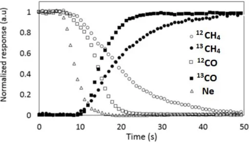
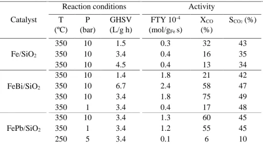
(9) Thèse de Alexandre Antônio Bento Carvalho, Lille 1, 2017. Figure List Chapter 1 Figure 1.1 Transformation of non-petroleum carbon resources into liquid fuels and chemicals via syngas. Reproduced from Zhang et al. [3]. ................................................................................... 7 Figure 1.2 Examples of CO activation pathways: (a) direct CO dissociation (carbide mechanism); and (b) H-assisted CO dissociation (carbide mechanism); (c) CO hydrogenation (CO-insertion mechanism). Reproduced from Todic et al. [64]......................................................................... 16 Figure 1.3 Two types of catalyst poisoning: selective to the active phase (a) and non-selective to the active phase (b). Black circles: active phase; gray circles: catalyst support Reproduced from Moulijn et al. [78]. ...................................................................................................................... 19 Figure 1.4 Two conceptual models for crystallite growth due sintering by (A) atomic migration or (B) crystallite migration. Reproduced from Bartholomew [79].............................................. 20 Figure 1.5 Example of surface and pore plugging of different carbon deposition on cobalt supported catalyst. Reproduced from Peña et al. [81]. ................................................................ 21 Figure 1.6 Deactivation regime for cobalt based catalyst. Synthesis conditions: 220 °C, 20 bar; commercial syngas feed: 50 vol% H2, 25 vol% CO and 25 vol% inerts; relative space velocity equal to 0.5. Reproduced from Van Berge et al. [14]. ................................................................ 26 Figure 1.7 Typical normalized isotopic-transient responses in product species P following an isotopic switch in reactant, R - *R, which appears in the product as P - *P. An inert tracer, I, is simultaneously removed to determine the gas-phase holdup of the reactor Reproduced from Shannon and Goodwin [106]....................................................................................................... 29 Figure 1.8 Possible reaction mechanisms for CH4 formation from CO hydrogenation. Adapted from Van Dijk [4] and Ledesma et al. [107]. .............................................................................. 38. Chapter 2 Figure 2.1 Schematic representation of the SSITKA set-up. (MFC = flow controller; PT = pressure transducer; PR = Manual pressure regulator; TI = temperature indicator; MS = mass spectrometer; GC = gas chromatograph; L = GC loop). ............................................................. 51 Figure 2.2 Flowrence (Avantium) unit in the RealCat high throughput platform. ..................... 56 Figure 2.3 Normalized concentrations during switches from 12CO/H2/He/Ne to 13CO/H2/He on CoPt/SiO2 for CO hydrogenation reaction. ................................................................................. 57. ix © 2017 Tous droits réservés.. lilliad.univ-lille.fr.
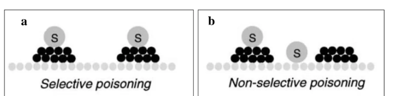
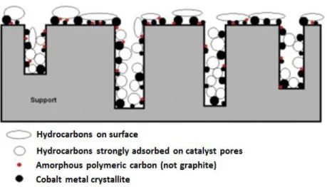
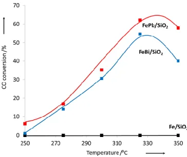
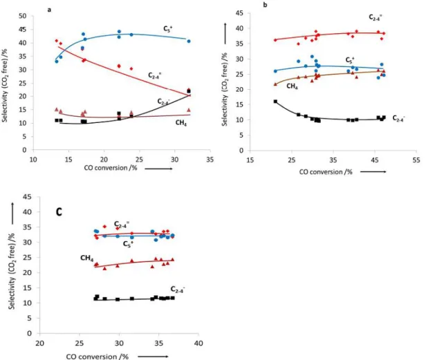
(10) Thèse de Alexandre Antônio Bento Carvalho, Lille 1, 2017. Chapter 3 Figure 3.1 Transient curve of 12CO and Ne during CO adsorption of silica supported iron catalyst at 25 °C........................................................................................................................................ 66 Figure 3.2 Carbon monoxide conversion on iron catalysts as a function of the reaction total pressure. Reaction conditions: T = 350 ºC, H2/CO = 1, GHSV = 3.4 L/g h. The data were obtained by increasing pressure in the row 0 – 2 – 5 – 10 – 20 bar. .......................................................... 68 Figure 3.3 Effect of the type of promoter on the CO conversion at different temperatures. Reaction conditions: P = 5 bar, H2/CO = 1, GHSV =3.4 L/g h. .................................................. 69 Figure 3.4 Effect of the type of promoter on the CO conversion as a function of time. Reaction conditions: P = 10 bar, H2/CO = 1, GHSV= 3.4 L/g h. ............................................................... 69 Figure 3.5 Effect of Bi promoter on the selectivity versus CO conversion. Reaction conditions: T= 350 °C, H2/CO = 1, P= 1 and 10 bar for FeBi/SiO2 and Fe/SiO2, respectively, GHSV = 1.5−27 L/g h............................................................................................................................................. 70 Figure 3.6 Selectivity to hydrocarbons versus CO conversion over Fe/SiO2 (a), FeBi/SiO2 (b) and FePb/SiO2 (c) catalyst. Reaction conditions: P = 10 bar, H2/CO =1, GHSV =1.5-27 L/g h. ...... 71 Figure 3.7 Selectivity to hydrocarbons versus CO conversion over the FeBi/SiO2 catalyst. Reaction conditions: P = 1 bar, H2/CO = 1, GHSV = 1.5-7.5 L/g h, T = 350 ºC. ....................... 72 Figure 3.8 (a) ASF plots and (b) chain growth probabilities over FeBi/SiO2 catalyst at different pressures. Reaction conditions: P = 1−20 bar, H2/CO = 1, GHSV = 1.5−3.4 L/g h, T = 350°C. The conversion was about 30%. ......................................................................................................... 73 Figure 3.9 XRD patterns of the catalysts after calcination. ........................................................ 75 Figure 3.10 XRD patterns of the catalysts after FT reaction. ..................................................... 75 Figure 3.11 Catalyst magnetization during cooling down after CO treatment at 350 ͦC. .......... 76 Figure 3.12 Methane formation rate in static hydrogenation of carbidized Fe/SiO2, FePb/SiO2 and FeBi/SiO2. ................................................................................................................................... 77 Figure 3.13 Conversion of CO over FeBi/SiO2, Bi/SiO2, Fe/SiO2, and mechanical mixture Fe/SiO2 + Bi/SiO2. Reaction conditions: H2/CO = 1, P = 10 bar, T = 350°C, GHSV = 3.4 L/g h, TOS = 100 h. ............................................................................................................................... 78 Figure 3.14 TEM-EDX images for Fe and Bi before after catalysis for the mechanical mixture Fe/SiO2 + Bi/SiO2 (see Figure 3.13). .......................................................................................... 79 Figure 3.15 SSITKA results over FeBi/SiO2. Reaction conditions: P = 1 bar, H2/CO = 2, GHSV = 8.4 L/g h, T = 350 ºC. ................................................................................................... 81 Figure 3.16 Rate of hydrogen production after exposure of the activated silica supported iron catalysts to water vapours. Reaction conditions: P = 1 bar, H2O flow 0.3 mL/h, T = 350 ºC..... 81 Figure 3.17 Rate of carbon dioxide production after exposure of the activated silica supported iron catalysts pretreated with water to CO at 300 °C. ................................................................. 82 Figure 3.18 Pb 4f XPS spectra of the FePb/SiO2 catalyst after calcination and exposure to carbon monoxide and syngas. ................................................................................................................. 83 Figure 3.19 CO conversion in function of time on stream for non-promoted and promoted cobalt catalysts at (a) Ratio H2/CO 2 and (b) Ratio H2/CO 5. Reaction conditions: 250 °C, GHSV = 12 000 mL/g h and 16 000 mL/g h. ............................................................................................. 85 Figure 3.20 CO conversion in function of ratio feed H2/CO for cobalt supported on silica, BEA, MOR and ZSM-5. Reaction condition: P ambient, 250 °C, GHSV = 13 500 mL/g h, 18 000 mL/g h and 23 850 mL/g h. ............................................................................................. 91 Figure 3.21 Transient curves of inert (Ne) and intermediates leading to CH4 from the switch of 12 CO/H2/He/Ne to 13CO/H2/He in function of ratio feed of H2/CO. Reaction condition: P ambient, 250 °C, GHSV =13 500 mL/g h, 18 000 mL/g h and 23 850 mL/g h. ........................................ 93 x © 2017 Tous droits réservés.. lilliad.univ-lille.fr.
(11) Thèse de Alexandre Antônio Bento Carvalho, Lille 1, 2017. Figure 3.22 Total number of sites (Ntotal = NCO + NCH4), number of CO sites (NCO), number of CH4 sites (NCH4) and SSITKA rate constant in ratio feed of H2/CO equal to 2 (a) and 5 (b). Reaction condition: P ambient, 250 °C, GHSV = 13 500 mL/g h, 18 000 mL/g h and 23 850 mL/g h. ............................................................................................................................ 94 Figure 3.23 Correlation between FT reaction rates measured from steady state experiments and concentration of CH4 intermediates evaluated from SSITKA. ................................................... 95 Figure 3.24 TEM image of cobalt based catalysts. .................................................................... 97. Chapter 4 Figure 4.1 Nitrogen adsorption/desorption isotherms obtained at -196.5 ͦC over the parent zeolites, Co/zeolite catalysts and Co/zeolite catalysts after the HPW treatment....................... 105 Figure 4.2 SEM images of zeolites. ......................................................................................... 105 Figure 4.3 TEM image of the catalysts before and after HPW treatment. The agglomerates of Co nanoparticles are indicated by white circle. .............................................................................. 107 Figure 4.4 Correlation between decrease of the microporous volume of Co/Zeolite-HPW in comparison with parent zeolite and theoretical volume of the introduced Co. ......................... 109 Figure 4.5 TEM image of the catalysts after HPW treatment. ................................................. 110 Figure 4.6 HAADF-STEM image of Co/BEA-HPW catalyst.................................................. 111 Figure 4.7 TPR reduction curves of Co/zeolite catalysts before and after treatment by HPW. 112 Figure 4.8 FTIR spectra observed after the adsorption of Py. .................................................. 113 Figure 4.9 Hydrocarbon distribution in liquid products. .......................................................... 116 Figure 4.10 Selectivity to hydrocarbons during FTS over Co/zeolite catalysts before and after cobalt extraction with HPW at CO conversion of about 20 %. Conditions: T = 250 ⁰C, P = 20 bar, H2/CO = 2, GHSV = 1.7-5 L/g h. .............................................................................................. 118 Figure 4.11 Anderson-Schulz-Flory SF distribution of hydrocarbons produced in FischerTropsch synthesis over Co/Zeolite nanocomposites before and after HPW treatment. ............ 120 Figure 4.12 Distribution of isomers, linear paraffins and linear olefins depending on the chain length for Co/ZSM-5 (open symbols) and Co/ZSM-5-HPW (filled symbols).......................... 121 Figure 4.13 Distribution of isomers, linear paraffins and linear olefins depending on the chain length for Co/MOR (open symbols) and Co/MOR-HPW (filled symbols). ............................. 121 Figure 4.14 Distribution of isomers, linear paraffins and linear olefins depending on the chain length for Co/BEA (open symbols) and Co/BEA-HPW (filled symbols). ................................ 122. xi © 2017 Tous droits réservés.. lilliad.univ-lille.fr.
(12) Thèse de Alexandre Antônio Bento Carvalho, Lille 1, 2017. Chapter 5 Figure 5.1 Normalized concentrations of 12CO and Ne during switches from 12CO/He/Ne to 13 CO/He at 100 °C. .................................................................................................................... 130 Figure 5.2 CO conversion and methane selectivity as functions of time on stream during FTS under methanation condition (1 atm, 250°C, H2/CO = 2, GHSV = 10 800 mL/g h). ............... 132 Figure 5.3 12CO (a) and 12CH4 (b) normalized concentrations during switches from 12 CO/H2/He/Ne to 13CO/H2/He on CoPt/SiO2 at different times on stream. Reaction conditions: 1 atm, GHSV = 10 800 mL/g h, 250 °C, gas composition 1CO/2H2/5.5He/0.5Ne................... 134 Figure 5.4 Concentration of CO (a) and CH4 (b) intermediates and their surface residence time versus time on stream. ............................................................................................................... 135 Figure 5.5 TEM images of the CoPt/SiO2 catalyst after different times on stream 1 h (a), 22 h (b), 150 h (c). ................................................................................................................................... 137 Figure 5.6 Histograms of cobalt agglomerate size distribution after 1 h and 150 h of reaction. ................................................................................................................................................... 138 Figure 5.7 TPH MS profiles (m/e = 15) measured on the CoPt/SiO2 catalyst at different reaction times (a), and after rejuvenation conducted after 22 h of reaction (b). ..................................... 139 Figure 5.8 SSITKA parameters before and after H2 rejuvenation (Reaction: 250 °C, H2/CO ratio = 2, 1 atm, GHSV= 10 800 mL/g h; rejuvenation: 250°C, 2 h, 1 atm, H2/N2 = 5/6. ................. 142 Figure 5.9 SSITKA data experimental and modeling results at 1h of reaction for M3 and M4. ................................................................................................................................................... 144 Figure 5.10 Predicted concentration of adsorbed CO according M1, M3, M4 and M5 models and experimental values of NCO as function of time on stream. Results are normalized by their corresponding value at 1 h. ....................................................................................................... 147 Figure 5.11 Predicted concentration of CH4 formation rate according M1, M3, M4 and M5 models and experimental values of activity as function of time on stream. Results are normalized by their corresponding value at 1 h. .......................................................................................... 147 Figure 5.12 Predicted concentration of adsorbed intermediate species according M1, M3, M4 and M5 models and experimental values of NCH4 as function of time on stream. Results are normalized by their corresponding value at 1 h. .......................................................................................... 148 Figure 5.13 Predicted (a) concentration of adsorbed intermediate species and (b) individual reaction rates (parallel routes for formation of Cα,ads and Cβ,ads from CO adsorbed) according model M3, as function of time on stream. ................................................................................. 149 Figure 5.14 Predicted (a) concentration of adsorbed intermediate species and (b) individual reaction rates (parallel routes for formation of Cα,ads and Cβ,ads from CO adsorbed, however, Cβ,ads is also formed from Cα,ads in a consecutive reaction) according model M4, as function of time on stream. .......................................................................................................................... 149 Figure 5.15 CO conversion as a function of time on stream for CoPt/Al2O3 without and with treatment with NH3. Reaction conditions: 1 atm, 220 °C, H2/CO = 5, GHSV = 14 400 mL/g h. ................................................................................................................................................... 152 Figure 5.16 Methane selectivity as a function of time on stream for CoPt/Al2O3 treated with pure syngas and ammonia. ................................................................................................................ 153 Figure 5.17 C2-C4 hydrocarbon selectivity as a function of time on stream in CoPt/Al2O3 with pure syngas and ammonia treatment. ........................................................................................ 153 Figure 5.18 Methane (a), C5+ hydrocarbon (b) selectivities and C2-C4 olefins to paraffins ratios (c) measured on supported cobalt catalysts as functions of carbon monoxide conversion in the presence of added acetonitrile and ammonia. ........................................................................... 154 Figure 5.19 TPD-MS profiles of alumina supported cobalt catalysts after the catalytic tests with syngas containing acetonitrile. .................................................................................................. 157 xii © 2017 Tous droits réservés.. lilliad.univ-lille.fr.
(13) Thèse de Alexandre Antônio Bento Carvalho, Lille 1, 2017. Figure 5.20 FTIR spectra of carbon monoxide adsorbed on the activated Co15%/Al 2O3 (a) and Co25%0.1%Pt/Al2O3 (b) catalysts before and after exposure to NH3; ...................................... 158. Chapter 6 Figure 6.1 General scheme of the procedure for the synthesis of metal-zeolite composite material. ................................................................................................................................................... 167 Figure 6.2 Preferential carbon deposition on the steps of cobalt nanoparticles and their removal during the rejuvenation.............................................................................................................. 168 Figure 6.3 Effect of NH3 treatment in the alumina supported cobalt catalyst. The poisoning of NH3 blocked the steps and corner sites of cobalt particles causing the loss on catalytic activity. ................................................................................................................................................... 170. xiii © 2017 Tous droits réservés.. lilliad.univ-lille.fr.
(14) Thèse de Alexandre Antônio Bento Carvalho, Lille 1, 2017. © 2017 Tous droits réservés.. lilliad.univ-lille.fr.
(15) Thèse de Alexandre Antônio Bento Carvalho, Lille 1, 2017. RESUMO O desempenho de catalisadores heterogêneos é geralmente atribuído a presença de sítios ativos. A concentração, a atividade intrínseca, a localização e a estabilidade destes sítios são os principais parâmetros de todos os sistemas catalíticos conhecidos. Métodos cinéticos transientes, como análise por SSITKA, são técnicas poderosas para o estudo cinético de reações catalíticas heterogêneas. Catalisadores à base de ferro com a presença de promotores metálicos (Bi e Pb) causaram notável aumento na taxa de produção de olefinas leves, criando a possibilidade de realizar a síntese de Fischer-Tropsch em condições amenas de reação e até mesmo em pressão atmosférica. Experimentos cinéticos transientes mostraram que a dissociação de CO é facilitada na presença de promotores devido a retirada de átomos de oxigênio pela ação do carboneto de ferro. O catalisador de cobalto suportado em zeólita mordenita apresentou maior valor da taxa de reação determinada por SSITKA entre todos os catalisadores suportados em zeólitas estudados. No entanto, ZSM-5 utilizada como suporte apresentou menor taxa de reação, provavelmente devido à localização das nanopartículas de cobalto na superfície externa da zeólita. A localização dos sítios ativos de cobalto em catalisadores bifuncionais formados por cobalto e zeólita apresentou grande impacto sobre a taxa de reação e em particular sobre a seletividade dos hidrocarbonetos. A proximidade entre os sítios ativos de cobalto e os sítios ativos de Brønsted demonstrou ser um parâmetro chave para obter uma alta seletividade e alto rendimento de hidrocarbonetos ramificados. O estudo combinando a análise SSITKA com técnicas de caracterização de catalisadores revelou que a deposição de carbono e a aglomeração de nanopartículas de cobalto durante a reação foram os responsáveis pela desativação do catalisador de cobalto suportado em sílica. A regeneração do catalisador via hidrogenação diminuiu o depósito de carbono e liberou parcialmente os sítios mais ativos para a dissociação de monóxido de carbono, assim como os sítios envolvidos na adsorção reversível de monóxido de carbono. A modelagem SSITKA demonstrou a presença de duas espécies intermediárias de carbono.. 1 © 2017 Tous droits réservés.. lilliad.univ-lille.fr.
(16) Thèse de Alexandre Antônio Bento Carvalho, Lille 1, 2017. RESUMÉ Les performances des catalyseurs hétérogènes sont généralement attribuées à la présence de sites actifs. La concentration, l’activité intrinsèque, la localisation et la stabilité de ces sites sont des paramètres importants de tous les systèmes catalytiques connus. Les méthodes cinétiques transitoires comme SSITKA sont des outils puissants pour mener à bien les études cinétiques des réactions catalytiques. La promotion des catalyseurs à base de fer avec des métaux utilisés pour la soudure (Bi et Pb) conduit à une augmentation remarquable de la vitesse de production des oléfines légères avec la possibilité d’effectuer la synthèse FischerTropsch dans des conditions très douces (basse pression) voire pression atmosphérique. Les expériences cinétiques transitoires ont démontré la facilité de la dissociation du CO à la surface du carbure de fer en présence des promoteurs par le piégeage d’atomes d’oxygène. Parmi tous les catalyseurs étudiés, les catalyseurs à base de zéolite de type mordenite ont présenté la valeur la plus élevée de la constante de vitesse SSITKA. En revanche, la ZSM-5 utilisée comme support présentait une vitesse de réaction la plus basse, probablement à cause de la localisation de nanoparticules de cobalt uniquement à la surface externe de zéolite. La localisation des sites actifs de cobalt dans les catalyseurs bifonctionnels à base de zéolite et de cobalt a un impact majeur sur la vitesse de réaction et en particulier sur la sélectivité en hydrocarbures. La proximité entre les sites actifs de cobalt et les sites actifs de Brønsted a été considérée comme un paramètre clef pour obtenir une sélectivité et un rendement plus élevés en hydrocarbures ramifiés. Le SSITKA couplé à des techniques de caractérisation a révélé que le dépôt de carbone et l'agglomération des nanoparticules de cobalt étaient responsables de la désactivation du catalyseur cobalt supporté par la silice. Le dépôt de carbone a entraîné une diminution du nombre d'intermédiaires carbonés qui produisent du méthane via leur hydrogénation. La régénération des catalyseurs sous hydrogène diminue le nombre d'espèces de carbone déposées et libère partiellement les sites les plus actifs d’adsorption dissociative et les sites les plus forts d'adsorption réversible du monoxyde de carbone. L'étude de modélisation SSITKA a démontré la présence de deux intermédiaires carbonés.. 2 © 2017 Tous droits réservés.. lilliad.univ-lille.fr.
(17) Thèse de Alexandre Antônio Bento Carvalho, Lille 1, 2017. ABSTRACT The catalytic performance of heterogeneous catalysts is usually attributed to the presence of active sites. The concentration, intrinsic activity, localisation and stability of these sites are major parameters of all known catalytic systems. Transient kinetic methods such as Steady State Transient Kinetic Analysis (SSITKA) are powerful tools for carrying out kinetic studies of heterogeneous catalytic reactions. Promotion of iron catalysts with metals used for soldering (Bi and Pb) results a remarkable increase in the light olefin production rate with the possibility to conduct Fischer-Tropsch synthesis at very mild reaction conditions (low pressure) and even at atmospheric pressure. Transient kinetic experiments showed facilitation of CO dissociation in the presence of promoters by scavenging O atoms from iron carbide. Cobalt catalyst supported by mordenite zeolite presented higher value of SSITKA rate constant among all catalysts studied. On the other hand, the ZSM-5 as support presented the lowest reaction rate, probably due to the localization of cobalt nanoparticles on the external surface of the zeolite. Localization of cobalt active sites in bifunctional cobalt-zeolite catalysts has a major impact on the reaction rate and in particular on the hydrocarbon selectivity. A proximity between the cobalt active site and Brønsted active sites was found to be a key parameter to obtain higher selectivity and yield of isomerized hydrocarbons. SSITKA combined with catalyst characterization revealed that carbon deposition and cobalt nanoparticle agglomeration were responsible for the deactivation of silica supported cobalt catalysts. The carbon deposition led to a decrease in the number of carbon-chemisorbed intermediates, which yield methane through their hydrogenation. Catalyst rejuvenation in hydrogen lessened the amounts of deposited carbon species and partially released the most active sites of carbon monoxide dissociative adsorption and stronger sites of carbon monoxide reversible adsorption. The SSITKA modeling demonstrated the presence of two intermediates carbon species.. 3 © 2017 Tous droits réservés.. lilliad.univ-lille.fr.
(18) Thèse de Alexandre Antônio Bento Carvalho, Lille 1, 2017. General introduction Fischer-Tropsch synthesis (FTS) represents a unique opportunity for manufacturing clean fuels and chemicals from both renewable and fossil resources [1-6]. In FischerTropsch (FT) technologies, fossil and renewable resources are first converted to syngas (mixture of carbon monoxide and hydrogen) via gasification, steam reforming and/or partial oxidation. The syngas then reacts on metal, carbide or sulfide catalysts to yield the value-added products. Different transition metals from Group VIII are used in FTS (e.g., cobalt, nickel, iron and ruthenium). Cobalt catalysts are suitable for the synthesis of middle distillates and waxes. Benefits of cobalt include are highest FT reaction rates compared to iron, a high selectivity to linear paraffins and low water–gas shift (WGS) activity. Considering high cost of cobalt, a high productivity and an extended catalyst life are required to make the FT process economically feasible [3, 7]. Transient kinetic methods including the steady state isotopic transient kinetic analysis (SSITKA) are powerful techniques for the kinetic investigation of heterogeneous catalytic reactions at molecular level. Originally developed by Happel [8] and Biloen [9], SSITKA can be used to determine site heterogeneity, concentration of different types of adsorbed reaction intermediates, surface residence time, activity distributions and site coverage [10] by inclusion of one or more stable isotopic labels in a reactant species [11]. SSITKA has been used to evaluate the effect of different promoters, support modification and cobalt particle size [6, 12-19] on the type, concentration and reactivity of the surface intermediates. SSITKA can be particularly useful to identify the origin of the loss of activity and selectivity, because it yields independent information about the number of active sites and their intrinsic activity. The goal of the thesis is to evaluate the intrinsic activity and localization of active sites in cobalt and iron based catalysts using a combination of transient kinetic methods such as SSITKA, extended physico-chemical characterization and catalytic tests under realistic conditions. 4 © 2017 Tous droits réservés.. lilliad.univ-lille.fr.
(19) Thèse de Alexandre Antônio Bento Carvalho, Lille 1, 2017. General introduction __________________________________________________________________________________. The present manuscript is divided into six chapters. Chapter 1 presents a literature review on FT synthesis and SSITKA methodology. Chapter 2 introduces the methods for catalyst preparation and characterization. Special attention is paid to the SSITKA technique and to the experimental and modeling procedures. Chapter 3 presents the role of promoters for iron and cobalt catalysts as well the effect of the zeolites structure on the catalytic performance and surface kinetic parameters. Chapter 4 presents a synthesis procedure to obtain cobalt-zeolite composite materials using an extraction with a heteropoly acid. Chapter 5 describes the SSITKA evaluation of the deactivation mechanism during FTS with pure syngas and syngas containing nitrogen compounds. Additionally, Chapter 5 demonstrated the manner in which the regeneration procedure affects the FT reaction at molecular level and results of SSITKA kinetic modeling. Chapter 6 presents the general conclusions and perspectives of the thesis. Major results of this thesis are published in the following articles: Carvalho, A.; Ordomsky, V. V.; Luo, Y.; Muniz, A. R.; Marcilio, N. R.; Khodakov, A. Y., Elucidation of deactivation phenomena in cobalt catalyst for Fischer-Tropsch synthesis using SSITKA. Journal of Catalysis, 2016, 344, 669-679. Carvalho, A.; Marinova, M.; Batalha, N; Marcilio, N.R., Khodakov, A. Y; Ordomsky, V.V. Design of pure pore incorporated metal-zeolite composite for highly efficient synthesis of isomerized hydrocarbons by Fischer-Tropsch synthesis. Catalysis Science & Technology, 2017, 7, 5019−5027. Ordomsky, V. V.; Carvalho, A.; Legras, B.; Paul, S.; Virginie, M.; Sushkevich, V. L.; Khodakov, A. Y., Effects of co-feeding with nitrogen-containing compounds on the performance of supported cobalt and iron catalysts in Fischer–Tropsch synthesis. Catalysis Today, 2016, 275, 84−93. Cheng, K.; Subramanian, V.; Carvalho, A.; Ordomsky, V. V.; Wang, Y.; Khodakov, A. Y., The role of carbon pre-coating for the synthesis of highly efficient cobalt catalysts for Fischer–Tropsch synthesis. Journal of Catalysis, 2016, 337, 260−271. Ordomsky, V. V, Luo, Y, Gu, B, Carvalho, A., Chernavskii, P. A.; Cheng, K., Khodakov, A. Y. Soldering of iron catalysts for direct synthesis of light olefins from syngas under mild reaction conditions. ACS Catalysis, 2017, 7, 6445−642.. 5 © 2017 Tous droits réservés.. lilliad.univ-lille.fr.
(20) Thèse de Alexandre Antônio Bento Carvalho, Lille 1, 2017. General introduction _______________________________________________________________________________. References 1.. Dry, M. E., Catalysis today 2002, 71 (3), 227-241.. 2.. Iglesia, E., D., Applied Catalysis A: General 1997, 161 (1), 59-78.. 3.. Khodakov, A. Y.; Chu, W.; Fongarland, P., Chemical Reviews 2007, 107 (5), 1692-1744.. 4.. van Steen, E.; Claeys, M., F., Chemical engineering & technology 2008, 31 (5), 655-666.. 5. Van Santen, R. A.; Ciobica, I. M.; Van Steen, E.; Ghouri, M. M., Advances in catalysis 2011, 54, 127. 6. van de Loosdrecht, J.; Ciobîcă, I. M.; Gibson, P.; Govender, N. S.; Moodley, D. J.; Saib, A. M.; Weststrate, K.-J.; Niemantsverdriet, J. W., ACS Catalysis 2016. 7. Saib, A. M.; Moodley, D. J.; Ciobîcă, I. M.; Hauman, M. M.; Sigwebela, B. H.; Weststrate, C. J.; Niemantsverdriet, J. W.; van de Loosdrecht, J. Catalysis Today 2010, 154 (3– 4), 271-282. 8.. Happel, J., Chem. Eng. Sci. 1978, 33, 1567.. 9.. Biloen, P., J. Mol. Catal. 1983, 21, 17.. 10.. Yang, J.; Chen, D.; Holmen, A. Catalysis Today 2012, 186 (1), 99-108.. 11.. Shannon, S. L.; Goodwin, J. G., Chemical Reviews 1995, 95 (3), 677-695.. 12. den Breejen, J. P.; Radstake, P. B.; Bezemer, G. L.; Bitter, J. H.; Frøseth, V.; Holmen, A.; Jong, K. P. d., Journal of the American Chemical Society 2009, 131 (20), 7197-7203. 13. Govender, N. S.; de Croon, M. H. J. M.; Schouten, J. C. Applied Catalysis A: General 2010, 373 (1–2), 81-89. 14.. Lohitharn, N.; Goodwin Jr, J. G., Journal of Catalysis 2008, 257 (1), 142-151.. 15.. Jongsomjit, B.; Panpranot, J.; Goodwin, J. G., J. Catal. 2003, 215, 66.. 16. van Dijk, H. A. J.; Hoebink, J. H. B. J.; Schouten, J. C., Chemical Engineering Science 2001, 56 (4), 1211-1219. 17. Rothaemel, M.; Hanssen, K. F.; Blekkan, E. A.; Schanke, D.; Holmen, A., Catalysis Today 1997, 38 (1), 79-84. 18. Ha, v. D., The Fischer-Tropsch synthesis: a mechanistic study using transient isotopic tracing. 2001. 19. Efstathiou, A. M.; Gleaves, J. T.; Yablonsky, G. S.; Che, M.; Vedrine, J. C., Characterization of Solid Materials and Heterogeneous Catalysts: From Structure to Surface Reactivity. 2012; p 1013.. 6 © 2017 Tous droits réservés.. lilliad.univ-lille.fr.
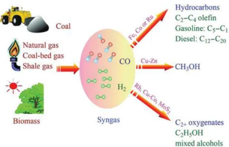
(21) Thèse de Alexandre Antônio Bento Carvalho, Lille 1, 2017. Chapter 1. Literature review 1.1 Fischer Tropsch synthesis Fischer Tropsch synthesis (FTS) is a chemical process used to convert syngas (mixture of carbon monoxide and hydrogen) in a mixture of long chain hydrocarbons and oxygenated species (Figure 1.1). Franz Fischer and Hans Tropsch discovered the process in 1922 employing an iron-based catalyst [1, 2]. Due to its fast technological development, FTS was already a commercial process in 1930.. Figure 1.1 Transformation of non-petroleum carbon resources into liquid fuels and chemicals via syngas. Reproduced from Zhang et al. [3].. 7 © 2017 Tous droits réservés.. lilliad.univ-lille.fr.
(22) Thèse de Alexandre Antônio Bento Carvalho, Lille 1, 2017. Chapter 1. Literature review. ________________________________________________________________________________. The FTS process is interesting for both academic and commercial purposes. However, its economic importance has been oscillating during recent history (post II World War). Accordingly to Van Dijk [4], FTS importance depends on the following four criteria: o The world reserves of carbon-containing resources; o Geographic location of carbon reserves; o Demand for cleaner feedstock; o Demand for reduction of CO2 emissions.. FTS technologies are named according to the used carbon feedstock, for example, the processes of Coal to-Liquids (CTL), Gas-to-Liquids (GTL) and Biomass-to-Liquids (BTL). This reference is recognized as XTL (“Anything-to-Liquids”) processes [5]. FTS involves a complex system of reactions with a desired and undesired products formed (see list below). Commonly, the desired products are olefins, paraffins and alcohols (compounds with greater commercial value) and the undesired may be methane and coke [1]. Desired reaction: Olefin:. nCO + 2nH2 → nH2O + CnH2n. Paraffin:. nCO + (2n+1)H2 → nH2O + CnH2n+2. Alcohols:. nCO + 2nH2 → CnH2n+1OH + (n – 1)H2O. Undesired reaction [6, 7]: Water Gas Shift Reaction (WGS):. CO + H2O → H2 + CO2. Boudouard reaction (carbon deposition) :. 2CO → C + CO2. Formation of metal carbides:. yC + xM → MxCy. Oxidation of metal:. xM + H2O → MOx + H2. As showed above the FTS produces a wide-ranging distribution of hydrocarbons. The reaction selectivity is described typically using the Anderson–Schulz–Flory (ASF) distribution model [8]. In the ASF distribution, the molar fraction (𝑀𝑛 ) of the hydrocarbon product with a carbon number of n preferably depends only on the chain-growth probability(𝛼), which is a function of the rates of chain growth and chain termination. Equation 1 determines the ASF distribution model. 8 © 2017 Tous droits réservés.. lilliad.univ-lille.fr.
(23) Thèse de Alexandre Antônio Bento Carvalho, Lille 1, 2017. Chapter 1. Literature review. ____________________________________________________________________________________. 𝑀𝑛 = (1 − 𝛼) ∙ 𝛼 𝑛−1. (1). FTS usually occurs at reaction conditions far from equilibrium [9]. Consequently, the product yields and selectivities are controlled by the reaction kinetics. The pressure applied are usually in the range of 15 to 20 bar. FT reaction is highly exothermic, with an average heat reaction of approximately -40 kcal/gmol [1]; consequently, efficient heat removal is required. The process temperature is the parameter responsible for the large spectrum of the FTS product distribution. For that reason, two fundamental FTS operation modes are defined. They are the lower temperature Fischer Tropsch (LTFT) and high temperature Fischer Tropsch (HTFT) processes. LTFT is characterized by temperatures between 200 °C and 240 °C and proceeds in the slurry bubble column (SBCR) and fixed bed reactors in industrial scale. Cobalt and iron catalysts are applied in this technology. The goal of LTFT is production of the C1 C100 linear paraffins and light olefins with a H2/CO ratio between 1.7 and 2.15 [10]. Accordingly to Dai et al. [11] and De la Osa et al. [12] LTFT is the most promising route for production of transportation fuels and chemical feedstocks from natural gas, coal and biomasses. HTFT processes are carried out in the range of 300 to 350 °C, and are generally applied to produce gasoline/naphta, olefins and oxygenates [13]. HTFT uses iron based catalysts and is usually performed in fluidized bed reactors.. 1.1.1 Fischer Tropsch catalysts The Fischer Tropsch catalysts make use of transition metals from the group VIII (iron (Fe), cobalt (Co), nickel (Ni), ruthenium (Ru) and rhodium (Rh)) as the active phase. Concerning the chemical state, there is a consensus that metallic cobalt (Coo) and metallic ruthenium (Ruo) act as the active phases for CO hydrogenation. For iron based catalysts, the iron carbides are recognized as the active phase [3]. Further investigation is necessary to identify and to understand how the chemical states of each catalyst affect FT catalytic performance. In the next paragraphs, special attention is given for iron and cobalt based catalysts. 9 © 2017 Tous droits réservés.. lilliad.univ-lille.fr.
(24) Thèse de Alexandre Antônio Bento Carvalho, Lille 1, 2017. Chapter 1. Literature review. ________________________________________________________________________________. Cobalt based catalysts presents the highest reaction rate, highest selectivity to linear paraffins, in particular at higher CO conversion, and low water–gas shift (WGS) activity. They are usually applied to obtain waxes and middle distillates [14, 15, 16]. In terms of cobalt catalyst design for FTS, De La Osa et al. [17] and Vosoughi [18] listed the general crucial factors as follows: o The support material with appropriate physico-chemical and textural properties; o The method of catalyst preparation with the inclusion of the precursor type, loading, drying, calcination and reduction procedures; o Optimum operational conditions in favor of higher CO conversion and C5+ selectivity. The activation of cobalt catalysts in hydrogen converts cobalt oxide phases to metallic Co. The Co° as the active phase may exist in two different crystalline forms, i.e. fcc (face centered cubic) and hcp (hexagonal close packing) phases [19]. For bulk Co, the hcp-phase is more stable at lower temperatures, but the fcc-phase becomes more stable when the size of Co particles becomes less than 20 nm [20]. Several studies have pointed out that the hcp-phase Co° is more active than the fcc-phase Co° in silica and alumina supported catalysts [19, 21, 22]. In addition, the gas composition applied on the catalytic reduction may influence the metallic cobalt phase obtained as well the catalyst support. For example, Elbashir et al. [23] have noticed in the used FT catalysts, the fcc-phase on silica support, while the hcp-phase was detected on alumina support. Cobalt catalytic performance is significantly affected by adsorption of CO + H2 reactants and intermediates by active sites [18, 24]. Additionally, an increase in the CO conversion is reported to be the responsible for the changes in the product selectivity, e.g. decreasing the methane selectivity with simultaneously increasing the C5+ hydrocarbon selectivity [25]. Moreover, at typical FTS conditions, the CO2 selectivity also increases with increasing CO conversion. This correlates with the higher WGS reaction rate at high water partial pressures. Fe may be described as the most complicated active metal due to the coexistence of several iron phases in the course of FT reaction [26]. These iron phases are: ε-Fe2C, ε’Fe2.2C, Fe7C3, χ-Fe5C2 and θ-Fe3C carbides as well as metallic iron, FeO and Fe3O4. This 10 © 2017 Tous droits réservés.. lilliad.univ-lille.fr.
(25) Thèse de Alexandre Antônio Bento Carvalho, Lille 1, 2017. Chapter 1. Literature review. ____________________________________________________________________________________. occurs because the activation energy to form iron carbides is lower or similar compared with the activation energy of the CO hydrogenation. The metallic iron phase is not stable under FT reaction conditions, but still can be present in the catalyst even at long time on stream [3, 27]. The spatial distribution of the active carbide particles on the support material plays an important role on the catalytic performance [28]. For example, Zhang et al. [3] observed that χ-Fe5C2 is the active phase for Fe-based catalysts. The product selectivity of Fe catalysts depends both on FT activity and water–gasshift (WGS) activity due to the fact that iron active phase is active in WGS reaction [25]. In terms of catalyst promoters, it is known that the alkali metals are able to suppress the methane selectivity and increase the selectivity to the C5+ hydrocarbons. The commercial iron catalyst is a multicomponent system. Potassium (K) is a recognized promoter to tune the product selectivity, resulting into an improvement of the selectivity to higher molecular weight hydrocarbons [29, 30, 31]. Another iron promoter with interesting results is the manganese (Mn) because it is capable to increase the CO conversion activity and decrease methane selectivity. Copper (Cu) may improve the iron reduction and carbidisation, while silica (SiO2) and alumina (Al2O3) supports acts for a structural improvement [32]. Rh-based catalysts have been pointed out as the most efficient for synthesis of the C2+ oxygenates [33-35]. Ni-based catalysts are typically used to obtain methane [36, 37]. For that reason, carbon monoxide hydrogenation with Ni catalysts have been suggested as a substitute process for synthesis of substitute natural gas (SNG). In addition, Ni is a relatively inexpensive metal [38]. Iron based catalysts are well recognized to exhibit both FTS and water-gas shift (WGS) reaction [25, 39]. The FT active catalytic species are generally supported on high surface area supports such as silica, alumina or zeolites. In the group of oxide supports, titania, alumina and silica are commonly used in FTS. In the case of zeolite supports, ZSM-5 [32], zeolite Y, zeolite L, and beta have been applied for synthesis of metal–zeolite FT catalysts. Zeolite is a material with elementary building units of SiO4 and AlO4 tetrahedra. Adjacent tetrahedra are linked at their corners via a common oxygen atom. This results in an inorganic macromolecule with a structurally distinct three dimensional framework [40].. 11 © 2017 Tous droits réservés.. lilliad.univ-lille.fr.
(26) Thèse de Alexandre Antônio Bento Carvalho, Lille 1, 2017. Chapter 1. Literature review. ________________________________________________________________________________. Zeolites are well known catalysts applied in the petrochemical and fine chemical industries [41, 42] due to their tunable acidity. Zeolites are characterized by high surface area and unique microporous structure that help to well disperse the catalyst active phase and obtain the shape selectivity. As about disadvantages, zeolites with high Si/Al ratio can exhibit high selectivity for undesired low molecular weight hydrocarbons due to their strong hydrocracking activities [43]. Furthermore, the high zeolite acidity may lead to the difficulties to reduce metal oxides at cation exchange sites and can increase catalytic deactivation rates. Only cobalt and iron based catalysts are considered economically feasible for large scale production [2, 39, 44, 45, 46, 47] and have deserved special attention in the literature. Because of high price and rarity, ruthenium has been restricted for research purposes or used as a promoter for cobalt catalysts [36, 48]. Nickel produces a high quantity of methane.. 1.1.2 Bifunctional catalysts and their application in FTS Bifunctional catalysts present two different active phases that assure catalytic sites for diverse reaction steps. Thus, the reaction occurs in successive steps involving two types of sites: metallic sites presenting the main function to hydrogenate and to dehydrogenate and acidic sites with the main function to crack or to isomerize [49]. These two types of sites affect the rate of different chemical steps, which can alter reaction pathways and consequently modify product distribution. Besides, a bifunctional process may require the diffusional steps of the intermediate species. A conventional example of process using a bifunctional catalyst is isomerization of n-hexane into methylpentanes using platinum-silica aluminate catalyst. While the hydrogenation and dehydrogenation occur on platinum, the isomerization takes place on the acid sites. Different steps of the reaction in bifunctional catalysts are catalyzed by different types of sites. If these steps occurs in series, both types of sites must be in proximity one to another. 12 © 2017 Tous droits réservés.. lilliad.univ-lille.fr.
(27) Thèse de Alexandre Antônio Bento Carvalho, Lille 1, 2017. Chapter 1. Literature review. ____________________________________________________________________________________. An advantage of the combination of a metal with an acid catalyst is the possible enhancement of the catalytic performance. This is due to the solid acid catalysts itself which suffers from fast deactivation by coking [50]. As commented by Guisnet [51], bifunctional redox-acid catalysts can decrease coke formation. Therefore, no longer a regenerative system is necessary and a new method of synthesis of catalysts to obtain less sensitives material to coking can be sidestepped. As commented in the above section, the zeolites supply acid sites to the catalyst. Zeolites present properties to be an “ideal” (highly active, stable and selective) acid catalyst due to their high number of acid sites and highly activity. The addition of a metal to the zeolite framework often guarantees a catalyst with high metal dispersion [50]. Pure acid zeolites are capable to crack and isomerize pentanes and hexanes [49]. The activity, stability and isomerization selectivity are usually increased if a hydrogenation phase is added to the zeolite. Therefore, the nature and reaction routes performed by both acid and hydrogenation sites are extremely important for the stability and selectivity of bifunctional zeolite catalysts. It is important to comment that the isomerization to cracking rate ratio depends also on the operating conditions applied and not only of the type of zeolite. Comparing zeolites with different structures is not an easy task. Furthermore, the isomer distribution is markedly dependent on the conversion [49]. Several groups reported [52, 53, 54] that the hydrocracking of FT heavy wax produces fuels in the middle distillate range. The bifunctional catalysts have been also tested in FTS in order to combine hydrocracking and isomerization of long-chain hydrocarbons in a single reactor to restrict hydrocarbon distribution to a specific range. The hybrid or composite catalysts for FTS contain an active metal component, such as Co, Fe and Ru for the growth of the primary straight chained hydrocarbons [55] and an acid zeolite catalyst for cracking and isomerization. These two types of sites are applied in FTS to obtain isoparaffins or diesel fuels (C10–C20 hydrocarbons) from the direct syngas conversion. Different process configurations have been selected for the use of bifunctional catalysts in FTS. For example, dual-bed configuration of the catalytic reactor with the FT 13 © 2017 Tous droits réservés.. lilliad.univ-lille.fr.
(28) Thèse de Alexandre Antônio Bento Carvalho, Lille 1, 2017. Chapter 1. Literature review. ________________________________________________________________________________. catalyst in the first layer and the zeolite or metal/zeolite in the second was tested by Zhao et al. [56] and Botes et al. [54]. Additionally, different method of catalyst preparation, such as mechanical mixing of FT catalysts with the zeolite [57, 58, 59] or the impregnation of the metal into the zeolite [52] have been studied. Below are some results from the literature concerning use of bifunctional catalysis in FTS. Botes et al. [54] proposed use of HZSM-5 in FTS in order to obtain high quality gasoline obtained by the step of skeletal isomerisation and aromatisation over acidic zeolites. The high quality is linked to the fact that the branched and aromatics hydrocarbons formed presented a high-octane value. The authors commented that addition of HZSM-5 to the Fischer–Tropsch process also improved production of gasoline range products due to the cracking of longer chain hydrocarbons and oligomerization of light olefins. Liu et al. [58] applied mechanical mixture of hybrid catalysts using cobalt supported on silica (Co/SiO2) and palladium supported on beta zeolite (Pd/BEA). The catalyst was applied for the direct production of gasoline ranged isoparaffins from syngas. They have found an interesting result about the effect of the interface between the Co/SiO2 and Pd/beta hybrids catalyst in the granual and powdery mixture. The granular hybrid catalyst showed lower CH4 selectivity and much higher isoparaffin selectivity than the powdery hybrid catalyst due to hydrogen spillover. The spillover was also observed by Tsubaki et al. [59] using a catalyst prepared from a physical mixture of three catalysts with different roles (Co/SiO2, Pd/SiO2 and ZSM5) in order to produce directly isoparaffin from syngas conversion. FTS and the hydrocracking of hydrocarbons occur in the same reactor. The hybrid catalyst life was remarkably extended after inclusion of Pd in the catalyst. In addition, Pd was able to decrease the methane selectivity. Hydrogenation of olefins was performed by the FT active metal catalyst, while the zeolite was able to perform wax cracking. Sarpini et al. [60] made use of the hierarchical-zeolite-supported cobalt catalyst, synthesized by impregnation method, in wax hydrocraking to shorter-chain hydrocarbons. The selectivity to the gasoline range of the C5-C11 fraction was increased. Bessell et al. [55] used impregnation method to synthesize a series of cobalt catalysts supported by zeolites (ZSM-5, ZSM-11, ZSM-12 and ZSM-34). The authors concluded that the activity was 14 © 2017 Tous droits réservés.. lilliad.univ-lille.fr.
(29) Thèse de Alexandre Antônio Bento Carvalho, Lille 1, 2017. Chapter 1. Literature review. ____________________________________________________________________________________. related to the channel size of the zeolite support. The 12 membered ringed ZSM-12 supported catalyst was the most active, followed by the two 10 membered ringed ZSM-5 and ZSM-11 supported catalysts, while the predominantly 8 membered ringed ZSM-34 supported catalyst was the least active. An example of the use of core-shell catalyst in bifunctional FT process is the work by Yang et al. [57]. The one-step synthesis of light isoparaffins from syngas via Fischer– Tropsch synthesis (FT) was performed using two types of core-shell-like zeolite capsule catalysts. Both catalysts effectively improved the selectivity to light isoparaffins, simultaneously depressing formation of heavy hydrocarbons, presenting a better catalytic performance than the traditional hybrid catalyst prepared by physical mixing. Another example involving of bifunctional catalysis is the syngas conversion to higher alcohols named as HAS. This reaction can be performed over bifunctional catalysts with one type of site to catalyze non‐dissociative CO adsorption for CO insertion and alcohol formation, and with the other site to dissociate CO and to form surface alkyl species [61]. In terms of zeolite material, ZSM-5 has been demonstrating to be an adequate support to combine both FTS and hydrocracking. It is due to the fact that ZSM-5 presents a specific porous structure, ability to perform shape selectivity, high acidity and resistance to coking and stability under FTS conditions [47, 55, 62]. It is important to remember that the choice of the preparation method for bifunctional catalysts for the direct synthesis of isoparaffins from syngas would depend on the zeolite acidity and its porous structure.. 1.1.3 Basic concepts of Fischer-Tropsch reaction mechanism The FT reaction mechanism is a topic widely studied in virtue of the relatively complexity of the subject [63]. Different approaches have been proposed over years, such as the carbide mechanism, CO insertion mechanism, hydroxycarbene mechanism and oxygenate enol mechanism. The reaction mechanism can be divided in elementary steps [64] to aid its understanding, as follow:. 15 © 2017 Tous droits réservés.. lilliad.univ-lille.fr.
(30) Thèse de Alexandre Antônio Bento Carvalho, Lille 1, 2017. Chapter 1. Literature review. ________________________________________________________________________________. 1) CO and H2 adsorption; 2) CO activation or chain initiation; 3) Chain propagation; 4) Chain termination. Among the four steps, the first step of CO and H2 adsorption occurs on the metal sites of the catalyst surface. The second step, named CO activation, is a matter of debate due to possibility of two types of dissociation: CO dissociation directly on the metal surface or hydrogen assisted CO dissociation [64, 65, 66]. These two CO activation pathways are shown in Figure 1.2, and lead namely to the carbide mechanism and to the CO insertion mechanism (both are going to be explained later).. H-assisted CO dissociation. Figure 1.2 Examples of CO activation pathways: (a) direct CO dissociation (carbide mechanism); and (b) H-assisted CO dissociation (carbide mechanism); (c) CO hydrogenation (CO-insertion mechanism). Reproduced from Todic et al. [64].. The chain propagation and chain termination (steps 3 and 4) show that FTS proceeds through a stepwise addition of a monomeric intermediate.[65]. A description of each step is available in the literature [67, 68, 69]. Valero et al. [70] and Davis et al. [71] have pointed out the carbide mechanism and CO insertion mechanism as the most likely FT reaction pathway. Nevertheless, several 16 © 2017 Tous droits réservés.. lilliad.univ-lille.fr.
Figure
![Table 1.2 Carbon species observed by Moodley et al. [53] and literature.](https://thumb-eu.123doks.com/thumbv2/123doknet/3672070.108701/38.918.142.779.266.703/table-carbon-species-observed-moodley-et-al-literature.webp)
+7
![Figure 1.8 Possible reaction mechanisms for CH 4 formation from CO hydrogenation. Adapted from Van Dijk [4] and Ledesma et al](https://thumb-eu.123doks.com/thumbv2/123doknet/3672070.108701/52.918.162.751.543.830/figure-possible-reaction-mechanisms-formation-hydrogenation-adapted-ledesma.webp)

Documents relatifs
