Science Arts & Métiers (SAM)
is an open access repository that collects the work of Arts et Métiers Institute of
Technology researchers and makes it freely available over the web where possible.
This is an author-deposited version published in: https://sam.ensam.eu Handle ID: .http://hdl.handle.net/10985/9748
To cite this version :
Caroline GUINARD, Vincent GUIPONT, Michel JEANDIN, Guillaume MONTAY, Jérémie GIRARDOT, Matthieu SCHNEIDER - Residual Stress Analysis of Laser-Drilled Thermal Barrier Coatings Involving Various Bond Coats - Journal of Thermal Spray Technology - Vol. 24, p.252-262 - 2014
Any correspondence concerning this service should be sent to the repository Administrator : archiveouverte@ensam.eu
Residual Stress Analysis of Laser-Drilled
Thermal Barrier Coatings Involving Various
Bond Coats
C. Guinard, G. Montay, V. Guipont, M. Jeandin, J. Girardot, and M. Schneider
The gas turbine combustion chamber of aero-engines requires a thermal barrier coating (TBC) by thermal spraying. Further heat protection is achieved by laser drilling of cooling holes. The residual stresses play an important role in the mechanical behaviour of TBC. It could also affect the TBC response to delamination during laser drilling. In this work, studies of the cracking behaviour after laser drilling and residual stress distribution have been achieved for different bond coats by plasma spray or cold spray. From interface crack length measured pulse-by-pulse after laser percussion drilling at 20! angle, the role of the various bond coats on crack initiation and propagation are investigated. It is shown that the bond coat drastically influences the cracking behaviour. The residual stresses profiles were also determined by the incremental hole-drilling method involving speckle interferometry. An original method was also developed to measure the residual stress profiles around a pre-drilled zone with a laser beam at 90!. The results are discussed to highlight the influence of TBCs interfaces on the resulting residual stresses distribution before laser drilling, and also to investigate the modification around the hole after laser drilling. It is shown that laser drilling could affect the residual stress state.
Keywords atmospheric plasma spray (APS), cold spray, functionally graded coatings, hole-drilling meth-od, laser drilling, residual stress determination, thermal barrier coatings (TBCs)
1. Introduction
The combustion chambers of gas turbines for aero-engines are protected by a thermal barrier coating (TBC). It consists of a metallic MCrAlY (M: Ni, Co,…) bond coat (that also acts as an oxidation resistant layer) and a ceramic top coat, typically yttria-stabilized zirconia (YSZ) by plasma spraying. The porous ceramic top coat fulfils the crucial function of insulating the metallic wall from the high temperature of combustion gases. In order to prevent the overheating of the component and achieve further heat protection, numerous cooling holes are drilled
throughout the chamber wall. Such holes enable a pro-tective air film that comes from the external side and flows along the internal face of the TBC-coated chamber. Combined with the porous ceramic, these holes drastically improve the component durability and service life and also contribute to achieving a higher efficiency and a better performance of the turbine. In the manufacture and repair industry of combustion chambers, laser drilling has be-come the conventional method because it is possible to precisely operate cooling holes by machining the ceramic and metallic layers simultaneously (Ref 1, 2). There are two different drilling methods: laser percussion or laser trepan. The more attractive mode from an industrial point of view is pulsed laser percussion drilling because several laser pulses are repeated with the same beam alignment making this drilling mode faster. The percussion mode also allows smaller diameters for holes with a typical range
of about 500lm. Moreover, an acute drilling angle is
necessary to maximize the cooling effect of the air film. Indeed, highly inclined holes limit the turbulence of the gas flow around the air inlet zone and therefore better prevent the formation of hot points due to hot gas stag-nation. With pulsed laser drilling, macro-cracks along the interfaces can be observed after the hole has been ma-chined. Unfortunately, by selecting high angles of inci-dence (typically <30!), the ceramic top coat is more sensitive to delamination at the leading edge zone if compared to the normal incidence (Ref 3–5). The dela-minated area could lead to the spallation of the ceramic top coat in service and direct exposure of the metal to the hot gases. Moreover, from such a scenario, it is also to be feared that the ejected spall debris might impact and
C. Guinard, V. Guipont, and M. Jeandin, MINES ParisTech, PSL - Research University, MAT - Centre des mate´riaux, CNRS UMR 7633, BP 87, 91003 Evry, France; G. Montay, Universite´ de Technologie de Troyes, ICD/LASMIS, 12 Rue Marie Curie, CS 42060, 10004 Troyes, France; and J. Girardot and M. Schneider, Arts et Me´tiers ParisTech, PIMM, 151 Boulevard de l!Hoˆpital, 75013 Paris, France. Contact e-mail: vincent.guipont@mines-paristech.fr.
damage downstream rotating parts. Therefore, the limi-tation of the pre-existing interfacial crack due to acute angle laser drilling is a key issue for the manufacture or the repair of TBC-coated combustion chambers with multi-hole patterns machined by laser drilling. Most of the work devoted to laser-drilled TBC are investigating the role of laser parameters (pulse energy, shape or frequency, drilling angle) or induced mechanical effects (ejected melt, assist gas, etc.) that could affect the area of the detri-mental crack generated at the top coat/bond coat (TC/BC) interface or the bond coat/substrate (BC/S) interface (Ref
6,7). In addition, materials characteristics like composi-tion, density, and thickness might have a role in the hole geometry and any cracking (Ref2,4).
In this work, we investigated the role of different materials and spraying processes used for bond coats in regard to interfacial cracks. The methodology was to achieve interrupted laser-drilling experiments with an acute drilling angle (20!). The purpose was to assess the crack initiation and propagation in cases of a "severe! drilling condition for various bond coats. From these experiments, we then focussed on the residual stress analysis of these various TBCs before and after laser drilling around the machined area using the incremental hole-drilling method involving conventional mechanical milling (Ref8,9). The goal was to bring out a discussion about the role of residual stresses generated during the deposition process and further modified by the laser-dril-ling process on crack generation. For the measurement of residual stress profiles around a laser-drilled hole, an ori-ginal method was developed involving specific TBC specimens with a pre-drilled hole using a normal incidence for the laser. The residual stress profiles were then com-pared between bulk and pre-drilled specimens for the various bond coats. The incremental hole was operated concentrically with a larger diameter to allow step-by-step removal of the material around a laser pre-drilled hole.
2. Materials and Methods
2.1 TBC Samples with Various Bond Coats
Three types of TBC bond coat were prepared: two of them were obtained by plasma spraying with a F100-Con-nex torch (Sulzer Metco, Wohlen, Switzerland) and the third one was processed by cold spray using a KINETICS#
3000-M System (CGT, Ampfing, Germany). The first type of plasma TBC was similar to conventional industrial
plas-ma TBC, involving a !90 +106 lm NiCrAlY powder
(Amdry 962; Sulzer Metco, Westbury, NY, USA) and a !125 +11 lm yttria stabilized zirconia powder (204NS; Sulzer Metco). The second type of plasma TBC was con-tinuously graded by increasing the YSZ powder feed rate while the NiCrAlY powder feed rate was simultaneously decreased during spraying the TBC coupon. The third type of TBC was obtained by combining a cold-sprayed bond
coat with!38 +5.5 lm CoNiCrAlY powder (Amdry 9951;
Sulzer Metco) to a plasma-sprayed YSZ top coat. Using helium as a processing gas, the fine CoNiCrAlY powder was
preferred to the coarse NiCrAlY powder to achieve a denser and more adhesive coating by cold spraying. The main spraying parameters are summarized inTable1. For plasma, plasma-graded and cold-spray bond coats, all the ceramic top coats were achieved with the same plasma parameters. Cobalt base Haynes#188 alloy plates (dimen-sions 150 9 40 mm2) were used as substrates. The plates were roughened (Ra = 2.8lm) by grit-blasting with a 250-lm corundum grit prior to coating operations (ALTISURF 500; ALTIMET, Annecy, France). All substrates had 2 mm thickness except for the plasma-graded bond coat for which a thinner substrate of 1.6 mm was selected. No significant macroscopic deformation was observed on all coated plates after spraying the whole TBC.
Optical images of the three different types of interface with various bond coats are shown in Fig. 1. The average roughness was lower for the cold-spray bond coat (Ra = 12.2lm) as compared to the plasma bond coat (Ra = 15.5lm). Due to the continuous spraying, the roughness of the plasma-graded bond coat could not be measured by profilometry. In addition to the as-sprayed condition selected for the cold spray CoNiCrAlY sample (Cf. Fig.1b), a fourth additional sample was prepared with an heat-treatment at 800!C during 4 h in air. This post-treatment of the cold-spray bond coat was further imple-mented to release the residual stress due to the severe plastic deformation underwent by the particles. The pur-pose was to assess the potential influence of residual stress on crack generation of two similar cold-spray bond coats with different stress state. It is worth to note that this treatment was carried out before the ceramic layer being plasma sprayed. Even if the presence of a grown oxide layer could affect the resulting adhesion and stress states, the rather low heat-treatment temperature that was se-lected for such oxidation-resistant alloys made the pre-sence of the oxide scale negligible.
2.2 Laser-drilling Experiments
TBC samples were drilled using a YAG laser with 1.06lm radiation (TRUMPF HL201P; HAAS-LASER, Schramberg, Germany) with the percussion mode. The laser power was selected at 15 kW with 1 ms pulse dura-tion and a constant focal distance. Each hole was drilled from the ceramic side implementing at least 4 pulses to come through the whole TBC-coated plate. The time be-tween each pulse was around 0.5 s to stand for the "on the fly! drilling mode that is generally used in industry. Two geometries of hole depending on drilling incidence (20! and 90!) were prepared for all types of TBC. In the case of the inclined beam at 20!, the drilled samples were pre-pared with holes involving 1, 2, 3, 4 and 10 pulses, respectively. After mounting, cutting and polishing the drilled samples, the observation of cross-sections in the middle of the hole was carried out by optical microscopy (Axiovert 405M; Carl Zeiss, Le Pecq, France). From this observation, TC/BC interface crack length was measured after each series of pulses. The TBC samples that were drilled with a normal incidence (90!) were used to achieve the residual stress measurements by the hole-drilling
method involving mechanical milling. The through-hole with the laser beam at 90! was obtained after 2 pulses only, but 4 pulses were needed to achieve a more regular shape with an average diameter of 500lm.
2.3 Residual Stress Analysis
The hole-drilling method is a semi-destructive relaxa-tion method to determine the residual stress depth profile in a structure (Ref8). When a blind-hole is machined in a
stressed material, it causes relaxation and deformation around the drilled area. In the case of non-uniform stress profiles, the relaxation strains can be measured on the surface after implementing a series of small depth incre-ments. The strains or displacements after each drilling step
can be recorded using astrain gauge rosette (Ref 9) or
optical methods (Ref 10). In this work, the Electronic
Speckle Pattern Interferometry (ESPI) technique with the phase shifting method has been successfully applied on the ceramic surface to measure the displacements after each
layer removal (see section2.3.1). This method is very
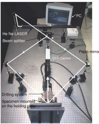
convenient because no specific device or surface prepa-ration of the ceramic top coat are necessary. A view of the experimental set-up for the incremental drilling and ESPI analysis is given in Fig.2.
From the experimental strain depth profile, the next procedural step is the residual stress computation involv-ing first a calibration of the strain/stress relaxation func-tion, and then the stress profile calculation (see section2.3.2). The calibration coefficient depends on the geometries of the specimen and of the incremental hole. It could be defined with higher relevance than experimen-tally by implementing a numerical simulation with Finite Element (FE) modelling (Ref9). The hole-drilling meth-od combining strain gauge measurements and a similar FE model applied to multi-layered thermally-sprayed coatings was introduced in a previous work devoted to YSZ coat-ings (Ref11,12). Further validation of this experimental/ numerical approach devoted to ceramic/metal coatings by Table 1 Main spraying parameters for MCrAlY bond
coats and YSZ ceramic
Sprays Parameters
Plasma spray
Plasma gases, L/min Ar/H2: 30/4
I (A) 500
Stand-off distance 80 mm Cold spray
Process gas, pressure, temp. He, 3.0 MPa, 500!C Standoff distance 41 mm
Gun traverse speed 200 mm/s
Nozzle 24TC by CGT
Incremental lateral step 1 mm Number of passes 1 Powder feedrate ~45 g/min
Fig. 1 Cross-section views of plasma, cold-spray and plasma-graded bond coats
Fig. 2 Set-up for residual stress analysis by the hole-drilling method with the Electronic Speckle Pattern Interferometry (ESPI)
thermal spray has been confirmed by several authors with the assessment of the influence of different sources of error (Ref13,14).
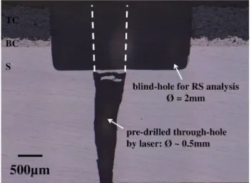
In this study, both as-sprayed and laser-drilled speci-mens were analysed by the hole-drilling method. The conventional method was applied to bulk coatings whereas a modified method to determine the residual stress profile around a pre-drilled hole was developed. For the latter, a concentric blind-hole was machined with a larger diameter than the trough-hole achieved by the la-ser. The same TBC plate was used for both analyses. The drilling parameters for the residual stress analysis are as follows: drilling speed: 5000 rpm, drilling tool: 3-teeth milling bit, no cooling medium, blind-hole diameter: 2 mm, incremental depth: 20lm. In Fig.3, a cross-section view of a laser-drilled specimen after the hole-drilling method is shown. The final depth of the blind-hole was 1 mm in order to analyse the residual stress profile in the ceramic in the bond coat and stop the analysis in the near region of the BC/S interface. It can be seen in Fig.3that some misalignment between the blind-hole and the pre-existing through-hole might have occurred. It was assumed in this study that the larger volume of material removed by milling was minimizing the error induced by the cen-tring of the two holes.
2.3.1 Displacements by ESPI. The temporal phase shifting method was used (Ref10,15,16). The beam phase of the interferometry set-up (see Fig.2) was shifted with a mirror mounted on a piezo-translator (laserk = 632.8 nm, angle h = 45!). In the present study, 4 phase steps were recorded and, for each phase step, the intensity I(x, y)k of a speckle pattern k was equal to:
Ikðx; yÞ¼ Ioðx; yÞ ð1 þ c x; yð Þ & cos / x; y! ð Þ þ /i" ðEq 1Þ
Fork = 1, 2, 3, 4 and where Io(x, y) is the intensity of the laser light, c(x, y) the fringe contrast and /(x, y) the optical phase to be determined. /i
is a value associated
with each pixel of the mapped region. The optical phase is calculated by: tan/ðx; yÞ ¼ I 4ðx; yÞ ! I2ðx; yÞ I1ðx; yÞ ! I3ðx; yÞ # $ ðEq 2Þ Measuring the phase map of one illuminated drilled area, the surface incremental displacement was determined from the phase map subtraction by:
Uxðx; yÞ ¼D/ðx; yÞk
4p sin h ðEq 3Þ
whereD/ðx; yÞ is the optical phase difference due to the
ob-ject deformation. The displacements map was recorded after each drilling step. An example of a TBC top surface dis-placement map obtained after several steps is given inFig.4. As represented in Fig.4, the experimental strain was calculated with a "digital! gauge length of 1.5 mm between the two same pixels for each increment (U1,U2: couple of displacements).
2.3.2 Residual Stress Profiles. Some general hypotheses for both bulk and pre-drilled cases are assumed to calculate stress from displacement measurement. (1) Isotropic and linear elastic behaviour of materials, (2) continuous dis-placements and homogeneous in-plane stress for each step, (3) normal stress negligible, (4) no plastic deformation due to stress release, and (5) no additional stress induced by milling. A further assumption was made in this work in order to consider only an equi-biaxial stress field within the material. This would lead to isotropic displacements after each drilling step. This deformation behaviour was ascertained with a Moire´ analysis on plasma-sprayed TBC by Wu et al. (Ref17). Therefore, from the theory of stress relaxation around a hole in cases of an equi-biaxial stress state, the released strain can be related to the residual stress according to Eq4, whererj andejare the residual stress and strain corresponding to the jth increment, and Ajjis a calibration coefficient depending of the geometry.
rj¼ ej
2Ajj ðEq 4Þ
Due to relaxation after each drilling step, the residual stress distribution remaining in the underneath layers
be-Fig. 3 Cross-section view of a laser-drilled TBC (90!) after the hole-drilling method
Fig. 4 Displacements map converted from ESPI phase image (e.g. hole depth 840lm)
comes modified. Therefore, the measured relaxation strain induced by further incremental drillings can be derived from the cumulative modification of stress due to the previous removals of the upper increments. The "true! residual stress profile resulting from a total sequence of j increments can be calculated by implementing an integral method (Ref8,9). This method written in a discrete form needs a numerical calibration of the strain/stress rela-tionship in each incremental layer after each drilling step, as expressed in Eq5.
eij¼ 2Aijri; with 1 ' i ' j ðEq 5Þ
In Eq5,Aijis a calibration coefficient that corresponds to a strain generated after the jth drilling step and induced by a unit hydrostatic stress in the ith increment. In this work, the series of calibration coefficients Aij for each incre-mental step were computed through a 3D finite element analysis (ABAQUS/CAE software). Two axisymmetric 3D models were built to simulate the strain relaxationeij after each increment. Details of the FE numerical ap-proach were described in previous works involving strain gauge measurements (Ref 11,12). In this work, the pre-sence of a pre-existing through-hole has also been con-sidered in one of the FE models. This development made this residual stress analysis of laser-drilled TBC fairly original. By incrementing all i and j indices in the FE model, the series of coefficients Aij were calibrated by predicting eij (ri= 1 MPa in Eq5). A schematic repre-sentation of the principle for FE calibration is given in Fig.5 for both models. These models for multi-layered coatings involved three different materials and a blind-hole of 2 mm in diameter. The pre-drilled mesh geometry exhibited a centred through-hole with a 0.5 mm diameter. Bottom nodes of the substrate were encastred and a per-fect adhesion between the material domains was assumed in the numerical models. The location of the two nodes to achieve the strain prediction in the FE models was similar to those of the two pixels for ESPI strain analysis.
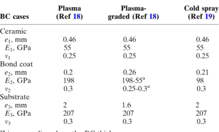
In the 3D FE model, the substrate and coatings were simulated involving elastic moduli and Poisson ratios found in the literature (Ref 18, 19), as summarized in
Table2. In cases of the plasma-graded bond coat, the composite modulus was the weighted average of the moduli of the two constituents according to a linear grading between NiCrAlY and YSZ along the thickness of the bond coat.
After computingAijcalibration coefficients for the two different FE models, an iterative analytical calculation of the "true! strain profile along the depth of j increments can
be implemented according Eq6 and experimental strain
measurementsemes j . ej¼ emesj ! X i¼j!1 i¼1 eij ðEq 6Þ
Finally, with an combination of Eqs4,5and6, the general iterative expression of the residual stress profile from the measured strain involving predictedAijcould be summa-rized as in Eq7. rj¼ 2Ajj emesj ! X i¼j!1 i¼1 2& Aij& ri " # ðEq 7Þ
3. Results and Discussion
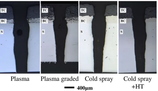
3.1 Observation of Holes and Cracked Interfaces 3.1.1 Laser Drilling at 90!. TBC samples with a per-pendicular through-hole were prepared for the residual stress analysis. Observation in the middle of the hole was carried out after laser drilling. The cross-section view for each of the four different interfaces, plasma, plasma-gra-ded, cold-spray and heat-treated cold-spray bond coats,
are given in Fig.6. A rather similar hole shape was ob-served for each TBC. The holes exhibited the typical geometry always found for normal incidence laser per-cussion drilling. A bell-mouth shape at the hole entry (ceramic side) followed with a taper leading to a smaller
hole exit. The same average diameter of 500lm was
measured for each case. A barrel-shape cavity could also be observed in the metal underneath the interfacial region. Such an effect is induced by the high pressure generated from the recoil of the ablated material with the sudden expansion of vapour and plasma. The creation of such a cavity could be explained by the energy trapped and violently dissipated in this region during the first pulse (Ref 20). This energy, mainly dissipated in the metal, is higher in cases of a TBC because a higher temperature range is needed to melt the ceramic in the first stage of the drilling process. Therefore, the barrelling effect in laser-drilled TBCs might be emphasized as compared to the laser drilling of bare materials.
As shown in Fig.6, no significant delamination (<0.2 mm) was detected for the different bond coats drilled at 90!. Therefore, as expected from the literature (Ref5,6), crack-free interfaces can be considered in the case of normal incidence laser percussion drilling. This made these samples suitable for further residual stress analysis by the hole-drilling method.
3.1.2 Laser Percussion Drilling at 20!. Laser-drilling experiments with an acute angle were achieved on TBC samples involving interrupted conditions. The purpose was to observe crack initiation and to follow propagation from 1 to 10 pulses. The crack position and length were estimated by optical microscopy on cross-section views. For all the TBCs in this study, four pulses were necessary to achieve a through-hole. By doing the series of next pulses up pulse #10, the recast material is no longer thrown out through the hole entry but through the hole exit. Therefore, it is interesting to show a detailed view of the interfacial region after pulse #4, as given in Fig.7for the various interfaces.
In agreement with well-established results about the laser drilling of plasma TBC with an acute angle (Ref3,5), the more critical interface was the TC/BC interface at the leading edge. In our study, one significant TC/BC crack
was detected for all TBCs except those with the plasma-graded bond coat. Moreover, further BC/S cracking was also evidenced in cases of cold-spray and plasma bond coats. With a heat treatment of the cold-spray bond coat, the TC/BC crack length was reduced and the BC/S crack was prevented (seeFig.7). The plasma-graded bond coat exhibited a very small crack (~0.2 mm) after the through-hole was completed. This made this coating solution very efficient and relevant for further optimization of improved TBC systems. In the case of plasma-graded bond coat, the crack path was located within the bond coat. This crack-resistant behaviour could be explained by the composite structure that probably favours several stops and devia-tions of the crack during its propagation. For the other cases, the TC/BC crack was mainly located within the ceramic with a rather straight profile coming up to the sharp peaks of the rough interface.
The evolution of the TC/BC crack length at the leading edge from pulse #1 to pulse #10 is given in Fig.8. It is obvious that the selection of the material and the spraying process for the bond coat drastically influenced the final length of the main critical TC/BC crack. From the longer to the smaller TC/BC crack length after pulse #10, the bond coats could be ordered from the weakest to the strongest interface as follows: cold-spray > cold-spray HT = plasma > plasma-graded. This confirmed the beneficial role of the graded bond coat, the poor resistance of the as-sprayed cold-spray bond coat, and the reinforcement of the cold-spray interface with a heat treatment at 800!C/4H/air prior to the plasma spraying of the ceramic layer.
From the cracking behaviour presented in Fig.8, it was also evidenced that the TC/BC crack was only initiated after pulse #2 for all the different bond coats of this study. This observation was in keeping with previous results about conventional plasma TBC, various drilling angles and interrupted conditions (Ref5). Indeed, after pulse #1 at 20!, only the ceramic was drilled and no interfacial crack was generated. After pulse #2, the drilling process has reached the metallic region and a TC/BC crack is initiated and could be of around 1 mm for the cold-spray interfaces. With further pulses, the interfacial crack is propagated until the hole was opened, except for the plasma-graded bond coat that kept a stable small crack. After pulse #4 and the through-hole being completed, the crack length was quite stabilized with no further significant propagation up to pulse #10. With inclined drilling, the crack propagation was mainly driven by the loading force and the bending moment applied on the ceramic overhang at the leading edge (Ref 5,6). The observation of speci-mens with interrupted drilling especially from pulses #2 to #4 is very informative for the observation of cracking mechanisms (initiation/propagation) in cases of the per-cussion mode. The presence of one asymmetrical barrel-ling effect could also be observed at the traibarrel-ling edge (see
Fig.7). The resulting cavity (empty or filled with recast material after drilling) may ‘‘concentrate’’ the harsh con-ditions (thermal and mechanical loads) in this interfacial region. This barrelling effect should be further studied by managing a specific drilling strategy to prevent the for-mation of such a barrel-shaped cavity.
Table 2 Materials data for 3D FE analysis
BC cases Plasma (Ref18) Plasma-graded (Ref18) Cold spray (Ref19) Ceramic e1, mm 0.46 0.46 0.46 E1, GPa 55 55 55 m1 0.25 0.25 0.25 Bond coat e2, mm 0.2 0.26 0.21 E2, GPa 198 198-55a 98 m2 0.3 0.25-0.3a 0.3 Substrate e3, mm 2 1.6 2 E3, GPa 207 207 207 m3 0.3 0.3 0.3
In our study, the plasma-graded bond coat led to an inclined hole that could be considered as free of detri-mental interfacial cracking. Both conventional plasma and
heat-treated cold-spray bond coats exhibited a similar cracking behaviour with a final TC/BC crack length of about 1.8 mm. The as-sprayed cold-spray bond coat had the poorest resistance to cracking with a final crack length of 3.8 mm. Cold-spray and plasma bond coats exhibited a different average roughness that could explain the actual difference of the crack lengths after pulse #10. Roughness could be involved in the intrinsic adhesion strength that might influence the cracking behaviour. Thus, the lower strength level should be in case of the lower average roughness that was obtained for the cold-spray bond coat. But after heat treatment of the cold-spray bond coat, while roughness was not modified (Ra = 12.2lm), it was assessed that the cracking behaviour was drastically im-proved for both TC/BC and BC/S cracks. The surface oxidation after heat treatment of the cold-spray bond coat must not be neglected because in theory it could affect the adhesive properties of the ceramic top coat. Nevertheless, the influence of stress release in the cold work micro-structure should certainly be considered, predominantly in regard to crack propagation. From this particular result, it
Fig. 6 Cross-section views of laser-drilled TBC (90!) for various bond coats (after 4 pulses)
Fig. 7 Cross-section views of laser-drilled TBC (20!) for various bond coats (after 4 pulses)
Fig. 8 Pulse-to-pulse evolution of TC/BC crack length at the leading edge of laser-drilled TBC (20!) for various bond coats
was evidenced that pre-existing residual stress within a bond coat could have a major role in crack propagation at the interface. In general, the actual steep gradient, due to different mechanical and thermal properties between layers within a multi-layered system, could play an important role in the resulting cracking behaviour. In this context, the use of a graded interface would also be ben-eficial to better accommodate the steep deformation during laser drilling. From this discussion, it was inter-esting to consider the analysis of the residual stress before and after laser drilling.
3.2 Residual Stress Analysis by the Hole-Drilling Method
Numerous papers have been devoted to the residual stress (RS) analysis of conventional plasma-sprayed TBC involving destructive, semi-destructive or fully non-destructive methods (Ref 21, 22). The main issue is to analyse an overall residual stress state owing to different sources of deformation during the process, also including the surface preparation. Among the existing methods, the hole-drilling method has shown numerous advantages because it allows the achieving of residual stress profiles. With the help of 3D FE analysis, it could be envisaged to achieve the experimental analysis by the hole-drilling method on local areas of shaped components and within a
multi-layered system like TBC (Ref 12). By developing
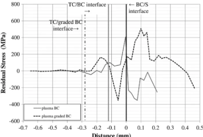
the hole-drilling method on laser pre-drilled TBC samples, the purpose was to estimate whether further residual stress could be induced and/or released by the laser-dril-ling process, and to compare the evolution of residual stress of various interfaces before and after laser drilling. 3.2.1 Residual Stress in Various As-sprayed TBCs. Plasma Spray Bond Coats RS profiles of plasma and plasma-graded bond coats are compared in Fig.9with two different posi-tions of the TC/BC interfaces. This difference was caused by a thicker intermediate layer for the plasma-graded BC as compared to the plasma-sprayed BC (See Fig.1).
With thermal spraying, the resulting residual stress could be a combination of: (1) tensile ‘‘quenching stress’’ generated during the solidification of the liquid droplets, (2) tensile or compressive ‘‘cooling stress’’ induced when cooling the deposit/substrate system, and (3) compressive ‘‘peening stress’’ at the near surface of the substrate due to grit blasting prior to spraying. Peening stress could also be generated within the bond coat when high velocity impacts are promoted, as for High Velocity Oxy-Fuel spraying (Ref 4, 22, 23). In the case of the plasma BC, the RS profile shown inFig.9is consistent with RS profiles and stress levels found in the literature with the modified layer removal method TBC (Ref22).
A tensile/compressive stress gradient (+400 MPa/ !250 MPa) was found at the BC/S interface. The tensile RS in the BC near the BC/S interface was mainly due to tensile quenching stress that could also induce compressive stress in the substrate. Near-surface compressive stress could be superimposed with pre-existing compressive stress by peening (even if some peening stress could be partially released by the heating during the first stage of the coating
process). Depending on the difference in the coefficients of thermal expansion (CTE) between the substrate and the bond coat, such a tensile/compressive gradient at the BC/S might be emphasized if CTEBC>CTES or softened if CTEBC<CTESby the cooling stress. In the case of the plasma-sprayed NiCrAlY bond coat, to be consistent with the RS profile obtained inFig.9, the coefficient of thermal expansion of NiCrAlY should be higher than those of the HAYNES188 substrate at the temperature of the coating process (which was not controlled in this work). This qualitative discussion highlights the need for actual values of CTEBCin temperature to better elucidate the sign and level of stress within the system just after the coating pro-cess. It also reveals the influence of the temperature of the process that also drastically affects the quenching and cooling stress. In our study, the use of the "low-power! F100-connex plasma torch (designed to spray in the internal diameter) allowed a moderate heating of the TBC. That is the main reason why the influence of CTE on cooling stress might be so important.
At the TC/BC interface of the plasma BC (see Fig.9), a compressive/tensile gradient by the cooling stress was evidenced but was less pronounced as compared to those at the BC/TC interface (!40 MPa/+120 MPa). In this interfacial region and within the ceramic coating, both quenching and cooling stress were released by micro-cracking. The low level of RS within the ceramic was also due to the intrinsic porosity that drastically decreased the elastic modulus as compared to the bulk YSZ.
In the case of plasma-graded BC, a similar discussion as for the plasma BC could be proposed to explain the very different RS profile that was measured, and shown for comparison in Fig.9. The plasma-graded BC exhibited a steep compressive/tensile stress gradient (!440 MPa/ +520 MPa) at the BC/S interface followed by a neutral/ tensile stress gradient (0 MPa/+160 MPa) at the TC/BC interface. In the graded BC, the increasing ratio of the ceramic mixed with the metal will provide a higher CTE in the bond coat than in the ceramic (CTEBC>CTETC) in the TC/BC region, and a lower CTE in the bond coat than
in the substrate (CTEBC<CTES) in the BC/S region.
Fig. 9 Residual stress profiles of TBC with plasma and plasma-graded BC
This is also accompanied by a similar evolution with Young!s moduli that will also amplify the stress calculated from the actual measured strain near the BC/S interface. Therefore, cooling stress could lead to two opposite stress gradients through each interface of the plasma-graded TBC. The stress gradient at the BC/S interface also exhibited some tensile stress within the bond coat in the near interface (in keeping with the quenching stress in this region). The high level of tensile stress within the sub-strate is more "unexpected!. In this case, it means that the peening stress has been neutralized by the tensile cooling/ quenching stress. This comparative discussion could be more enlightened by noting that the thermal history dur-ing the plasma-graded BC was probably very different from those of the plasma BC. Firstly, it led to a higher onset temperature for the cooling because no interruption between TC and BC spraying was operated. Secondly, the addition of a ceramic into the metal promoted higher temperatures in this region. All these thermal aspects combined with a thicker intermediate layer in the case of plasma-graded BC explain the predominant influence and the high level of cooling stress within a TBC with a plas-ma-graded BC. Finally, such very different RS profiles will be strongly modified in service, but could play an impor-tant role because laser-drilling operations are achieved just after the thermal-spraying process.
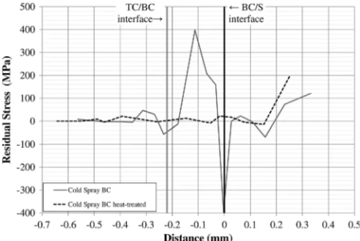
Cold-Spray Bond Coats Much less work has been devoted to RS profiles in cold-spray coatings (Ref24,25). Residual stresses within the coating are mainly induced by a peening effect with severe plastic deformation (cold work microstructure) of particles. The peening effect during cold spraying could also affect the substrate with compressive stress. Thermal effects that could generate cooling stress could not be avoided. The heat transfer will be more effective for a very thick coating with a long time exposure to the hot gases and to the flow of high velocity particles. This was not the case in this study because a single pass coating was implemented, while helium was used as the processing gas heated to 500!C. RS profiles of cold-spray and heat-treated cold-spray bond coats are plotted inFig.10.
As-sprayed cold-spray CoNiCrAlY led to a tensile/ compressive stress gradient (+160 MPa/!400 MPa) at the BC/S interface and a rather slight tensile/compressive stress (+50 MPa/!50 MPa) at the TC/BC interface. The cold-spray CoNiCrAlY bond coat is mainly tensile along its thickness with a tensile peak (+400 MPa) in the middle of the bond coat. If only peening stress was generated by high velocity impact of solid particles, it would have led to compressive stress. In the case of a single pass coating, such a tensile peak within the cold-spray BC could not be explained by a multi-pass coating with inter-pass stress release, as suggested in the literature (Ref25). In a recent work, tensile residual stress was already detected without ambiguity in an aluminium cold-spray coating (with
nitrogen processing gas at 350!C and 2.5 MPa) using
in situ deflection measurements made by Suhonen et al. (Ref24). According to these authors, thermal stress could be the origin of tensile stress within a cold-spray layer. In our case, the use of helium with a higher thermal
con-ductivity than nitrogen, and also processed at high
tem-perature and pressure (see Table2), might have a
significant influence on heat transfer to the coating system and the resulting thermal stress. Moreover, in the case of our TBC system, tensile stress within the cold-spray BC might also be induced by cooling stress due to the ceramic by plasma spraying. As for plasma bond coat, this result brings out the lack of data about the thermo-mechanical properties of cold-sprayed coatings in the as-sprayed state for the better understanding of residual stress generation during the process. In Fig.10, it can be clearly seen that heat-treated cold-sprayed CoNiCrAlY TBC led to a stress-free sample. This result is consistent with the annealing of a cold worked microstructure and the release of stress at the TC/BC interface.
3.2.2 Residual Stress After Laser Drilling in Various TBCs. The various RS profiles before and after laser drilling (drilling incidence 90!) are given in Fig.11 for each interface. In laser-drilled specimens, the stress around the hole results from the stress release due to the material removal but also from stress induced by the laser. Even if the pulse duration is short, the high rate thermal and mechanical effects are inherent in the process. These effects are mainly driven by the hot gas recoil pressure but also by the melted material (flow of ejected material or recast material lining the hole). In the case of normal incidence drilling, the first pulse was deep enough to drill the ceramic, the bond coat and the substrate simulta-neously. Therefore, the mismatch of properties between each layer could play an important role on the resulting stress release or generation during the first pulse.
For each TBC interface in Fig.11a–d, it was evidenced that a RS profile obtained in a laser-drilled area is always different from those measured in a bulk region. Each RS analysis before and after laser drilling was carried out on the same TBC plate. This means that the laser-drilling process drastically affects the RS state around the hole. Moreover, from the large volume of material removed by the hole-drilling method, it is likely that the RS modifi-cation by laser drilling is a long-range modifimodifi-cation (in mm).
Fig. 10 Residual stress profiles of TBC with cold-spray and cold-spray heat-treated BC
In the case of plasma BC, it can be seen that the stress gradients at the interfaces (Fig.11a) were released after laser drilling. This led to a smooth profile that might reveal a stress-free region around the hole. In contrast, the RS profile was magnified after laser drilling in the case of plasma-graded BC (Fig.11b). A higher tensile/compressive stress gradient (+760 MPa/!550 MPa) at the BC/S inter-face was measured and one tensile/compressive stress gra-dient (+240 MPa/!320 MPa) was created after laser drilling at the TC/BC interface. The RS profile of the cold-spray BC (Fig.11c) after laser drilling was also magnified as compared to the RS profile measured in the corresponding bulk TBC. The RS profiles of the plasma-graded BC and cold-spray bond coat exhibited a nearly similar shape with two steep gradients at both the interfaces. In the case of the heat-treated cold-spray BC (Fig.11d), a compressive/ten-sile stress gradient (!120 MPa/+160 MPa) was detected at the TC/BC interface after laser drilling. This gradient could not be induced by the relaxation of the through-hole be-cause the specimen was free of stress before laser drilling. Therefore, it is suggested that the TC/BC stress gradient was generated by the laser-drilling process itself. In Fig.11a–d, such TC/BC stress gradients can be observed except for the plasma BC. This TC/BC region seems to be very sensitive to RS modification during laser drilling. The thermal and mechanical effects that could affect the multi-layered
material are complex but, according to these results, they cannot be neglected.
4. Conclusion
Different TBCs with various bond coats were prepared by plasma (NiCrAlY conventional or plasma-graded) and cold-spray (CoNiCrAlY as-cold-sprayed or heat-treated). The interface cracking behaviour during laser percussion drilling was ana-lysed through interrupted laser experiments in cases of severe drilling conditions (20! beam incidence). With the TC/BC crack length measurements at one pulse and up to ten pulses, the bond coats could be ordered from the weakest to the strongest interface as follows: cold-spray > cold-spray HT = plasma > plasma-graded. The observation of specimens especially from pulses #2 to #4 is very informative for the observation of cracking mechanisms (initiation/propagation). The plasma-graded bond coat led to a laser-drilled TBC free of interface cracks. The other interfaces led to a final TC/BC crack length of about 1.8 mm and up to 3.8 mm in the case of cold-spray CoNiCrAlY without heat-treatment.
RS profiles were analysed by the hole-drilling method with ESPI measurements in the cases of as-sprayed and laser-drilled TBC. This method was successfully introduced to determine the RS profile around a pre-drilled hole (laser
beam with normal incidence). RS profiles were measured for each interface before and after laser drilling. Plasma-spray BC and plasma-graded BC exhibited two opposite stress gradients at the BC/S interface and a nearly similar gradient at the TC/BC interface with a zero stress within the ceramic. These results highlighted the predominant role on RS profile of cooling stress and CTE at the temperature of the process (not the service temperature). This RS state could play an important role because laser-drilling opera-tions are achieved just after the thermal-spraying process. CoNiCrAlY cold-spray bond coats exhibited a tensile peak within the layer (+400 MPa). This "unexpected! sign of stress could still be attributed to thermal stress, but further study is needed to better clarify the stress formation in CoNiCrAlY cold-spray coatings. After heat-treatment, the cold-spray TBC was annealed and free of stress. It is con-cluded that the residual stress modification within the cold-spray layer could have a predominant role in crack forma-tion and propagaforma-tion.
RS profiles are drastically modified after laser drilling. Stress could be slightly released or enhanced as compared to RS profiles before laser drilling. In the case of the stress-free heat-treated cold-spray BC, a stress gradient was detected at the TC/BC interface after laser drilling. Such a stress gradient was necessarily generated by the laser-drilling process itself. The TC/BC interface seems to be very sensitive to RS modification during laser drilling. Further work is needed to better discriminate the stress release due to material removal from the stress induced by the laser drilling. To that purpose, smooth mechanical drilling without heat and strong mechanical effects should be prepared experimentally with a similar diameter to those obtained by percussion laser drilling. Further ana-lysis with the hole-drilling method applied on such pre-drilled holes will ascertain the actual influence of laser drilling on the RS state around the hole. This aspect might be crucial to envisage multi-hole patterns for their influ-ence on the component geometry and also to better understand the role of RS profiles on interfacial damage. It is concluded that both the nature of the bond coat and the residual stress can have a major role in eliminating ceramic delamination during laser drilling.
Acknowledgments
This work was founded by the French Research Agency (‘‘Mate´riaux et Proce´de´s’’ ULTRA project) and the ASTech ‘‘poˆle de compe´titivite´’’ for aeronautics. Industrial partners of the project (CRMA, LASAG, Laser Technologie, SNECMA – SAFRAN group) are gratefully acknowledged for their contributions.
References
1. W. Schulz, U. Eppelt, and R. Poprawe, Review on Laser Drilling I. Fundamentals, Modeling, and Simulation, J. Laser Appl., 2013, 25, p 012006
2. A. Corcoran, L. Sexton, B. Seaman et al., The Laser Drilling of Multi-layer Aerospace Material Systems, J. Mater. Process. Technol., 2002, 123, p 100–106
3. H.K. Sezer and N. Li, Mechanisms of Acute Angle Laser Drilling Induced Thermal Barrier Coating Delamination, J. Manuf. Sci. Eng., 2009, 131, 051014, p. 6
4. K.T. Voisey and T.W. Clyne, Laser Drilling of Cooling Holes Through Plasma Sprayed Thermal Barrier Coatings, Surf. Coati. Technol., 2004, 176, p 296-306
5. J. Girardot, M. Schneider, L. Berthe et al., Investigation of Delamination Mechanisms During a Laser Drilling on a Cobalt-Base Superalloy, J. Mater. Process. Technol., 2013, 213, p 1682-1691 6. J. Kamalu, P. Byrd, and A. Pitman, Variable Angle Laser Drilling of Thermal Barrier Coated Nimonic, J. Mater. Process. Technol., 2002, 122, p 355-362
7. H.K. Sezer, L. Li, and S. Leigh, Twin Gas Jet-Assisted Laser Drilling Through Thermal Barrier-Coated Nickel Alloy Sub-strates, Int. J. Mach. Tools Manuf., 2009, 49, p 1126-1135 8. J. Lu, Handbook of Measurement of Residual Stresses, The
Fairmont Press, Lilburn, 1996
9. G.S. Schajer, Hole-Drilling Residual Stress Measurements at 75: Origins, Advances, Opportunities, Exp. Mech., 2010, 50, p 245-253
10. F.V. Dı´az, G.H. Kaufmann, and O. Mo¨ller, Residual Stress Determination Using Blind-Hole Drilling and Digital Speckle Pattern Interferometry with Automated Data Processing, Exp. Mech., 2001, 41, p 319-323
11. G. Montay, A. Cherouat, J. Lu et al., Development of the High-precision Incremental-step Hole-drilling Method for the Study of Residual Stress in Multi-layer Materials: Influence of Tempera-ture and Substrate on ZrO2-Y2O38 wt.% Coatings, Surf. Coat.
Technol., 2002, 155, p 152-160
12. G. Montay, A. Cherouat, A. Nussair et al., Residual Stresses in Coating Technology, J. Mater. Sci. Technol., 2004, 20, p 81-84 13. E. Obelode and J. Gibmeier, Residual Stress Analysis on Thick
Film Systems by the Incremental Hole-Drilling Method: Simu-lation and Experimental Results, Exp. Mech., 2013, 53, p 965-976 14. T. Valente, C. Bartuli, M. Sebastiani et al., Implementation and Development of the Incremental Hole Drilling Method for the Measurement of Residual Stress in Thermal Spray Coatings, J. Therm. Spray Technol., 2005, 14, p 462-470
15. W. An and T.E. Carlsson, Speckle Interferometry for Measure-ment of Continuous Deformations, Optics Lasers Eng., 2003, 40, p 529-541
16. G. Cloud, Optical Methods of Engineering Analysis, Cambridge University Press, 1995
17. L. Wu, J. Zhu, and H. Xie, Numerical and Experimental Inves-tigation of Residual Stress in Thermal Barrier Coatings During APS Process, J. Therm. Spray Technol., 2014, 23, p 653-665 18. J. Matejicek, S. Sampath, P.C. Brand et al., Quenching, Thermal
and Residual Stress in Plasma Sprayed Deposits: NiCrAlY and YSZ Coatings, Acta Materi., 1999, 47, p 607-617
19. F. Raletz, G. Ezo!o, M. Vardelle et al., Characterization of Cold-Sprayed Nickel-Base Coatings, in : ITSC 2004, Thermal Spray 2004 : Advances in Technology and Applications, 10-12 may 2004, Osaka (2004)
20. C.Y. Yeo, S.C. Tam, S. Jana et al., A Technical Review of the Laser Drilling of Aerospace Materials, J. Mater. Process. Tech-nol., 1994, 42, p 15-49
21. A. Portinha, V. Teixeira, J. Carneiro et al., Residual Stresses and Elastic Modulus of Thermal Barrier Coatings Graded in Porosity, Surf. Coat. Technol., 2004, 188--189, p 120-128
22. C.R.C. Lima, J. Nin, and J.M. Guilemany, Evaluation of Residual Stresses of Thermal Barrier Coatings with HVOF Thermally Sprayed Bond Coats Using the Modified Layer Removal Method (MLRM), Surf. Coat. Technol., 2006, 200, p 5963-5972
23. Y.C. Tsui and T.W. Clyne, An Analytical Model For Predicting Residual Stresses in Progressively Deposited Coatings Part 1: Planar Geometry, Thin Solid Films, 1997, 306, p 23-33
24. T. Suhonen, T. Varis, S. Dosta et al., Residual Stress Develop-ment in Cold Sprayed Al, Cu and Ti Coatings, Acta Mater., 2013, 61, p 6329-6337
25. S. Rech, A. Trentin, S. Vezzu et al., Influence of Pre-Heated Al 6061 Substrate Temperature on the Residual Stresses of Multi-pass Al Coatings Deposited by Cold Spray, J. Therm. Spray Technol., 2011, 20, p 243-251