A THESIS SUBMITTED TO
THE UNIVERSITY OF QUEBEC AT CHICOUTIMI IN PARTIAL FULFILMENT OF THE REQUIREMENTS
FOR THE DEGREE OF MASTERS IN ENGINEERING
by ANIL ARICI
DEVELOPMENT OF Al-SI-MG ALLOYS FOR PERMANENT MOLD CASTING AND HIGH-PRESSURE VACUUM DIE CASTING APPLICATIONS
Québec, Canada
MÉMOIRE PRÉSENTÉ À
L’UNIVERSITÉ DU QUÉBEC À CHICOUTIMI COMME EXIGENCE PARTIELLE DE LA MAITRISE EN INGÉNIERIE
par ANIL ARICI
DÉVELOPPEMENT D'ALLIAGES D'AL-SI-MG POUR LES APPLICATIONS DE COULÉE DE MOULE PERMANENTES ET DE COULÉE SOUS PRESSION
À HAUTE PRESSION
Québec, Canada
i Abstract
The aim of this study is to design and to develop new aluminum alloys for high pressure vacuum die casting applications which can provide higher mechanical properties and superior light weighting solution for automotive body structures. In the meantime, the present study focuses on the effect of transition elements, namely, vanadium (V), zirconium (Zr) and molybdenum (Mo) on mechanical properties and microstructural features of permanent mold casting and high-pressure vacuum die casting AlSi10Mg and AlSi8Mg alloys.
In this work, eight distinct permanent mold casting alloys with different V, Zr and Mo addition combinations were designed and investigated to select the promising alloys for high pressure vacuum die casting (HPVDC) applications. After evaluation of mechanical properties on as-cast condition, the permanent mold casting alloys were solution heat treated at 500 °C and 540°C up to 8 hours, followed by water quenching, and then subjected to an aging treatment at 170°C for 4 hours. Hardness measurements were performed to reveal the effect of different addition combinations and define the optimum heat treatment parameters. The hardness evaluation of as cast permanent mold castings showed that additions of V and Zr (HPD-101) elements improve hardness, yield strength, ultimate tensile strength and elongation of AlSi10Mg alloy by 14%, 28%, 29% and 25% respectively. On the other hand, the additions of V, Mo (HPD-103) resulted in 7%, 21%, 12% and 3% improvement in those properties respectively. Moreover, the additions combination of V, Zr and Mo (HPD-103) into AlSi10Mg resulted in an improvement of hardness, yield strength, ultimate tensile strength and elongation by 7%, 21%, 12, and 2% respectively on as-cast condition. The V, Zr additions into AlSi8Mg (HPD-802) improved hardness, yield strength ultimate tensile strength and elongation by 11%, 24%, 27% and 33% respectively, whereas the additions of V, Mo (in HPD-801) enhance these properties by 5%, 19%,
ii
23% and 23%. Meanwhile, the additions of V, Zr, Mo in AlSi8Mg (HPD-803) resulted an outstanding improvement in yield strength, ultimate tensile strength and elongation values with increase of 27%, 32% and 61% respectively.
In order to optimize heat treatment parameters, hardness values of the experimental alloys were evaluated in two different temperatures with different soaking times. According to hardness results, the heat treatment parameters are optimized as solution heat treatment at 540°C for 2 hours, followed by water quench and aging at 170°C for 4 hours. In consideration of hardness and tensile properties on as-cast and heat-treated conditions, HPD-101 (V, Zr), HPD-802(V, Zr) and also HPD-803 (V, Zr, Mo) were chosen for further microstructural investigations and high-pressure vacuum die casting investigation.
The microstructures of selected alloys were examined by optical microscopy, scanning electron microscopy and transmission electron microscopy. The results indicate that addition of V and Zr into permanent mold casting alloys (HPD-101 and HPD-802) is beneficial to refine eutectic Si particles in the microstructures. Moreover, it can reduce length of Fe-rich intermetallic phases up to 20%, and also decrease the aspect ratio of intermetallic phases, proving the beneficial impact of V, Zr elements on intermetallic phase modification. On the other hand, V, Zr and Mo (HPD-803) additions remarkably decreased the length of the intermetallic phases by 40% in comparison with AlSi8Mg alloy. It is established that the main influence of V, Zr and Mo additions appeared in the formation of new distinct intermetallic phases such as (AlSi)3(ZrTi) and
(Al-Si-Fe-Mn-V-Mo), modification of present intermetallic phases and silicon particles on as-cast condition. Following the solution heat treatment, partial dissolution of intermetallic phases and precipitation of dispersoids were observed, which would play vital role to improve mechanical properties.
iii
In consideration of permanent mold casting (PM) alloys, high pressure vacuum die casting (HPVD) alloys were produced in six different composition including two base alloys with different level of Si. It is established that additions of V, Zr (10-I) metals into AlSi10Mg HPVD castings resulted in improvement of hardness, yield strength and ultimate tensile strength by 10%, 8% and 8% respectively while no significant change was reported for elongation of the alloy on as-cast condition. The additions of (V, Zr) into AlSi8Mg improved the hardness yield strength and ultimate tensile strength by 5%, 13% and 5% respectively while a slight reduction was observed in elongation in comparison to base alloy. On the other hand, in 8-III alloy (V, Zr, Mo), hardness, yield strength and ultimate strength was improved by 9%, 15% and 8% respectively, whereas the elongation also increased by 6%. After evaluation of mechanical properties on as-cast condition, optimization of heat treatment parameters was studied for T5 and T6 tempers. For T6 temper, although highest hardness values for HPVD castings were achieved via solution heat treatment at 540°C x 3h + WQ + 170°C x 4h, the heat treatment parameters are optimized as solution heat treatment at 520°C x 3h + WQ + 170°C x 4h in consideration of blistering effect. For T5 temper, two different conditions were selected; (1) 170°C x 4h and (2) 210°C x 1h. According to evaluation of mechanical properties, 10-II (V, Zr), 8-II (V, Zr) and 8-III (V, Zr, Mo) alloys were selected for further microstructural investigations.
The microstructural features of selected alloys on as-cast and heat-treated conditions were studied via optical microscopy, scanning electron microscopy and SEM-EBSD mapping. The results showed that the additions of (V, Zr) into AlSi10Mg alloy reduced the average grain diameter from 87.7 µm to 43.1 µm, revealing beneficial impact of V, Zr metals on grain modification. Besides, two new distinct intermetallic phases were observed which are (1) (AlSi)3(ZrTi) and (Al-Si-Fe-V-Mn). Moreover,quantitative analysis of intermetallics indicated
iv
that aspect ratio and equivalent diameter of intermetallic phases reduced by 20% and 15% respectively, proving the beneficial influence of V and Zr on modification of intermetallic phases. It is also seen that heat treatment can further induce a reduction in the size and volume fraction of intermetallics and results the spherodizitation of the eutectic Si particles. Moreover, it was observed that V, Zr additions can promote the formation of dispersoids and thereby further increase the mechanical properties of the alloys in comparison to as-cast condition. It is also found that number density of dispersoids in 8-III (V, Zr, Mo) alloy were higher than those in 8-II (V, Zr) and 8-I (Base) alloys, resulting further improvement in mechanical properties. The thermal analysis of HPVDC alloys showed that V, Zr and Mo additions resulted in formation of three different exothermic peaks in DSC curves and the additions can reduce the onset and peak temperatures of β’’, β’ and β precipitations in base alloys.
v
Résumé
Le but de cette étude est de concevoir et de développer de nouveaux alliages d’aluminium pour les applications de moulage sous pression à haute pression, capables de fournir des propriétés mécaniques plus élevées et une solution légère supérieure de pondération pour les structures de carrosserie automobile. Dans l’intervalle, la présente étude porte sur l’effet des éléments de transition, à savoir le vanadium (V), le zirconium (Zr) et le molybdène (Mo) sur les propriétés mécaniques et les caractéristiques microstructurales du moulage permanent et du moulage sous vide à haute pression AlSi10Mg et Alliages AlSi8Mg.
Dans ce travail, huit alliages de coulée en moule permanents distincts avec différentes combinaisons de V, Zr et Mo ont été conçus et étudiés pour sélectionner les alliages prometteurs pour les applications de moulage sous vide à haute pression (HPVDC). Après évaluation des propriétés mécaniques à l'état coulé, les alliages de coulée en moule permanents ont été soumis à un traitement thermique en solution à 500° C et jusqu'à 8 heures, suivi d'une trempe à l'eau, puis soumis à un traitement de vieillissement à 170° C pendant 4 heures. Des mesures de dureté ont été effectuées pour comparer la dureté de chaque alliage et définir les paramètres optimaux de traitement thermique. En fonction des résultats de dureté, les paramètres de traitement thermique sont optimisés en tant que traitement thermique en solution à 540 ° C pendant 2 heures, suivi d'une trempe à l'eau et d'un vieillissement à 170 ° C pendant 4 heures. Des essais de traction sur des alliages tels que moulés et traités thermiquement ont également été effectués. Compte tenu des propriétés mécaniques des conditions de coulée et de traitement thermique, les alliages HPD-101 (V, Zr), HPD-802 (V, Zr) et HPD-803 (V, Zr, Mo) ont été choisis pour des investigations microstructurales plus poussées. et les applications de moulage sous vide à haute pression.
vi
Les microstructures des alliages sélectionnés ont été examinées par microscopie optique, par microscopie électronique secondaire et par microscopie électronique à transmission. Les résultats indiquent que l'ajout de V et de Zr (HPD-101 et HPD-802) dans un alliage de coulée en moule permanent est bénéfique pour affiner les particules de Si eutectiques dans les microstructures. Par ailleurs, les additions de V, Zr et Mo (HPD-803) n’ont pas apporté de modification supplémentaire aux particules de silicium. Il est établi que l'influence principale des additions de V, Zr et Mo est apparue dans la formation de phases intermétalliques distinctes, la modification de phases intermétalliques et de particules de silicium et le renforcement de la solution à l'état de coulée. Après le traitement thermique en solution, la dissolution partielle des phases intermétalliques et la précipitation de dispersoïdes ont joué un rôle essentiel dans l'amélioration des propriétés mécaniques.
En ce qui concerne les alliages de coulée en moule permanents, des alliages de moulage sous pression à haute pression ont été produits en six compositions différentes, y compris deux alliages de base avec une teneur différente en Si. Les mesures de microdureté des alliages HPVDC sont effectuées à l'état fondu, puis l'optimisation des paramètres de traitement thermique a été étudiée pour les états T5 et T6. Sur la base des valeurs de dureté et des possibilités de formation de cloques, les paramètres de traitement thermique sont optimisés en tant que traitement thermique en solution à 520 ° C pendant 3h, suivi d'une trempe à l'eau puis d'un vieillissement à 170 ° C pendant 4h. De plus, des alliages de 10-II (V, Zr), 8-II (V, Zr) et 8-III (V, Zr, Mo) ont été sélectionnés pour des investigations microstructurales plus poussées.
Les caractéristiques microstructurales de certains alliages dans des conditions de coulée et de traitement thermique ont été étudiées par microscopie optique, microscopie électronique secondaire et cartographie SEM-EBSD. Les résultats ont révélé que l'addition de métaux V, Zr et
vii
Mo entraînait une réduction significative de la taille des grains et la formation de nouvelles phases intermétalliques. On voit également que le traitement thermique peut induire une réduction de la taille et de la fraction volumique des intermétalliques et entraîne la sphérodisation des particules de Si eutectiques. De plus, il est indiqué que les additions de V, Zr et V, Zr, Mo peuvent grandement favoriser la formation de dispersoïdes et augmenter ainsi davantage les propriétés mécaniques des alliages par rapport à l'état de coulée. L’analyse thermique des alliages HPVDC a montré que les additions de V, Zr et Mo entraînaient la formation de trois pics exothermiques dans les courbes DSC et que ces additions pouvaient réduire les températures de début et de pointe des précipitations β ’’, β ’et β dans les alliages de base.
viii
Acknowledgment
First and foremost, I would like to express my sincere thanks to my supervisor Prof. X. Grant Chen for his continuous trust and support during this research project. As a mentor, his contributions to my personal and professional life are priceless. It has been an honour to be his student. I would also like to express my gratitude to my co-director Prof. Zhang Zhan for his significant contribution to my research project. Without his guidance, this study would have never been accomplished.
I would like to convey my sincere gratitude to Prof. Duygu Kocaefe, and Prof. Yasar Kocaefe for giving me a chance to make my dream come true. During my study, they have always been supportive and treated me as their son.
I am very grateful to my friend Ahmet Deniz Bas for his endless support and help. His dedication, diligence and helpfulness will always remain an inspiration in my future. I am also thankful to my dear friends Sena Ozturk and Kaan Berki Karabay who supported and helped me during my study. They made my life much more fun and easier. My gratitude and appreciation for their friendship cannot be expressed. Many thanks are also to my colleagues and friends Dany Racine, Dave Girard, Dr. Kun Liu, Pier-luc Prive, Samuel Dessureault, Xiaoming Qian, Redouane Farid, Siyu Tu, Mengyun Liu, Chen Li, Wei Xu, Erdem Tekin for their kind support, friendship and help.
Finally, but no means least, I cannot find words to express my gratitude to my parents and my brother whose love and guidance are with me in whatever I pursue. I also thank my future wife Gozde Kaptikacti for her unceasing encouragement and everlasting support during my study.
ix
This project was financially supported by Natural Science and Engineering Research Council of Canada (NSERC) and Rio Tinto Aluminum through the NSERC Industry Research Chair in the Metallurgy of Aluminum Transformation at Université du Québec à Chicoutimi (UQAC). I would like to thank both organizations for their support during my study.
x
PUBLICATIONS
Conference Papers and Presentations
1. Effect of Zr and V Additions on Microstructure and Mechanical Properties of the AlSi10Mg Cast Alloy, 16th International Conference on Aluminum Alloys, Quebec, Montreal,
Canada 17-21 June 2018
2. Effect of Zr, V, Mo Additions on Mechanical Properties and Microstructure of AlSi8Mg Cast Alloy, TMS 2020, San Diego, California, USA, 23-27 February 2020
xi
“Dedicated to Republic of Turkey, the country of beauty and generosity…
“We only need one thing, to be hardworking…” M. Kemal Ataturk
xii
Table of Contents
Abstract ... i Résumé ... v Acknowledgment ... viii Chapter 1 ... 2 INTRODUCTION ... 21.1 Definition of the Problem ... 2
1.2 Objective ... 5
1.3 Methodology ... 5
REFERENCES ... 7
Chapter 2 ... 10
LITERATURE REVIEW ... 10
2.1 Aluminum-Silicon Casting Alloys ... 10
2.1.1 Aural TM Alloys ... 15
2.2 Casting Processes ... 16
2.2.1 Permanent Mold Casting (Pm)... 16
2.2.2 High Pressure Die Casting (HPDC) ... 18
2.2.3 High Pressure Vacuum Die Casting (HPVDC) ... 21
2.3 Role of Alloying Elements... 23
xiii 2.3.2 Effect of Mg Addition ... 23 2.3.3 Effect of Mn Addition ... 24 2.3.4 Effect of Fe Addition ... 25 2.3.5 Effect of Zr Addition ... 26 2.3.6 Effect of Ti Addition ... 26 2.3.7 Effect of Mo Addition ... 26 2.3.8 Effect of V Addition ... 27 REFERENCES ... 29 Chapter 3 ... 35 EXPERIMENTAL PART ... 35 3.1 Alloy Design ... 36 3.2 Alloy preparation ... 37
3.2.1 Preparation of permanent mold casting alloys ... 37
3.2.2 Preparation of high-pressure vacuum die casting alloys... 38
3.3. Heat Treatments ... 40
3.4 Characterization of Microstructures ... 41
3.4.1. Sample preparation for microstructure observation ... 41
3.4.2 Optical Microscopy observation and image analysis... 42
3.4.3 SEM observation and elemental analysis ... 43
xiv
3.5 Electrical Conductivity Analysis ... 44
3.6 Evaluation of Mechanical Properties ... 45
3.6.1 Microhardness Measurements ... 45
3.6.2 Evaluation of Tensile Properties ... 46
3.7 Differential Scanning Calorimetry ... 48
Chapter 4 ... 50
EFFECT OF ZR, V AND MO ADDITIONS ON MECHANICAL PROPERTIES AND MICROSTRUCTURE OF PERMANENT MOLD CASTINGS ... 50
4.1 The Mechanical Properties of the Experimental Alloys ... 50
4.1.1 Hardness and Tensile Properties on As-Cast Condition ... 50
4.1.2 Optimization of Heat Treatment Parameters ... 54
4.1.3 The Mechanical Properties on T6 Condition ... 56
4.2 Selection of the Promising Alloys ... 59
4.2.1 Promising Alloy Selection for 10% Si Containing Alloys ... 59
4.2.2 Promising Alloy Selection for 8% Si Containing Alloys ... 60
4.3 Microstructure Investigation of the Promising Alloys... 61
4.3.1 Microstructure of 10% Si Containing Alloys ... 61
4.3.2 Microstructure of 8% Si Containing Alloys (Base-8, HPD 802, and HPD 803) ... 71
4.4 Summary ... 82
xv
Chapter 5 ... 88
EFFECT OF V, ZR AND MO ON MICROSTRUCTURE AND MECHANICAL PROPERTIES OF HPVD CASTINGS ... 88
5.1 The Mechanical Properties of HPVD Castings ... 88
5.1.1 The Hardness Evaluation of HPVD Castings on As Cast Condition... 88
5.1.2 The Tensile Properties of HPVD Castings on As-cast Condition ... 89
5.2 Optimization of the Heat Treatment Parameters ... 91
5.2.1 Hardness Evaluation of T5 Heat Treated Alloys ... 92
5.2.2 Tensile Properties of T5 Heat Treated Alloys ... 94
5.2.3 Hardness Evaluation of T6 Heat Treated Alloys ... 96
5.2.4 Tensile Properties of T6 Heat Treated Alloys ... 99
5.3 Microstructure Investigation of HPVDC Alloys ... 101
5.3.1 Microstructure Analysis of 10%Si Containing Alloys on As-Cast Condition ... 102
5.3.2 Microstructure Analysis of 10% Si Containing Alloys on T6 Heat-Treated Condition ... 105
5.3.3 Microstructure Analysis of 8%Si Containing Alloys on As-Cast Condition ... 111
5.3.4 Microstructure Analysis of 8% Si Containing Alloys on T6 Heat-Treated Condition ... 115
5.4 Thermal Analysis of High-Pressure Vacuum Die Casting Alloys... 122
xvi
REFERENCES ... 128
Chapter 6 ... 130
GENERAL CONCLUSIONS AND RECOMMENDATIONS FOR FUTURE WORK ... 130
6.1 Conclusions ... 130
xvii
List of Figures
Figure 2-1: Al-Si-Mg ternary phase diagram [4]. ... 11
Figure 2-2: Optical images of cast A356 alloys in unmodified (a) and 200ppm modified (b) conditions [12] ... 12
Figure 2-3: Illustration of T6 heat treatment steps on Al-Cu phase diagram [13]. ... 14
Figure 2-4: Schematically illustration of a permanent mold casting process [18]. ... 17
Figure 2-5: A typical micrograph of AlSi10Mg alloy produced by permanent mold casting method ... 18
Figure 2-6: Schematic illustration of high pressure die casting application [18]. ... 19
Figure 2-7: A schematic illustration of high-pressure vacuum die casting application [29]. ... 21
Figure 2-8: Optical microscopic images of Al-8% Si alloys, showing the porosity distribution in high pressure die casting (a) and high pressure vacuum die casting (b) ... 22
Figure 2-9: A typical micrograph of AlSi10Mg alloy produced by HPVDC method. ... 22
Figure 2-10: Effect of Mg content on T6 yield strength of Al-Si alloys [36] ... 24
Figure 2-11: Brittle Fe-rich intermetallic phase in AlSi10Mg casting ... 25
Figure 2-12: TEM micrograph of Al-(Fe,Mo)-Si dispersoids in interdendritic regions (a) and EDS spectrum of the dispersoids (b) [45]. ... 27
Figure 3-1: Electrical resistance furnace that used to produce the experimental alloys ... 37
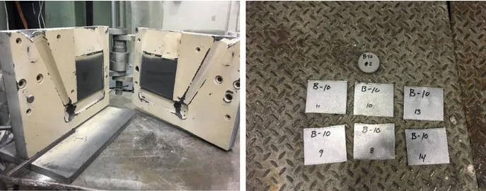
Figure 3-2: Permanent mold that was used to produce the experimental alloys and cast plates of the Base10 alloy ... 38
Figure 3-3: High pressure vacuum die casting machine and produced cast plates of a sample ... 40
xviii
Figure 3-5: Mounting and polishing machines that used for the metallographic sample preparation
... 42
Figure 3-6: Nikon Eclipse ME600 Optical Microscope ... 43
Figure 3-7: Scanning electron microscope used for microstructure observations ... 43
Figure 3-8: TEM, JEM-2100 transmission electron microscope. ... 44
Figure 3-9: Portable Fisher Sigmacope Electrical Conductivity Measurement System ... 45
Figure 3-10: Vickers microhardness machine used for the hardness measurements ... 45
Figure 3-11: Schematic illustration of Tensile Test Specimen ... 46
Figure 3-12: Instron-8801 tensile testing machine. ... 47
Figure 3-13: Differential scanning calorimetry system (DSC 8000) used in thermal analysis. ... 48
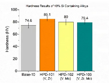
Figure 4-1: Hardness results of 10% Si containing alloys on as-cast condition ... 50
Figure 4-2: Hardness results of 8% Si containing alloys on as-cast condition ... 51
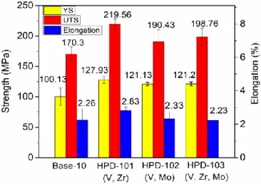
Figure 4-3: Tensile properties of 10% Si containing alloys on as-cast condition ... 52
Figure 4-4: Tensile properties of 8% Si containing alloys on as-cast condition ... 54
Figure 4-5: Evaluation of the hardness as function of holding times at the solution temperature 500°C (a,b) and at the solution temperature of 540°C (c,d) ... 55
Figure 4-6: Hardness evaluation of the experimental alloys on as-cast and T6 heat treated conditions. ... 56
Figure 4-7: Tensile properties of 10% Si containing alloys on T6 (540 °C x 2h + 170 °C x 4h) condition ... 57
Figure 4-8: Tensile properties of 8% Si containing alloys on T6 (540 °C x 2h + 170 °C x 4h) treated condition. ... 58
xix
Figure 4-9: Optical microstructure images of the Base10 (a,c) and HPD 101 (b,d) alloys on as cast condition. ... 62 Figure 4-10: SEM backscattered electron image of the base alloy (a) and EDS spectrum of Fe-rich phase (b) ... 63 Figure 4-11: SEM backscattered electron image of HPD101 alloy (a), and EDS spectrum of Zr-rich intermetallic phase (b), and V-Zr-rich intermetallic phase (c) ... 63 Figure 4-12: Optical images of the Base10 (a) and HPD101 (b) alloys on heat-treated condition ... 64 Figure 4-13: SEM backscattered electron images of the Base10 (a) and HPD101 (b) alloys. ... 65 Figure 4-14: Equivalent Diameter of Si particles for Base-10 and HPD 101 alloy in both as-cast and heat-treated conditions ... 66 Figure 4-15: Volume Fraction (a) and aspect ratio (b) of the intermetallic phases in the Base10 and HPD 101 alloys on both as cast and heat-treated conditions ... 67 Figure 4-16: Length of the intermetallic phases in Base-10 (a) and HPD-101 (b) alloys. ... 67 Figure 4-17: Dispersoid zone and dispersoid free zone in the solution heat treated Base-10 (a) and HPD-101 (b) microstructures. ... 68 Figure 4-18: Secondary electron images of etched Base-10 (a) and HPD-101 alloys after solution heat treatment ... 69 Figure 4-19: Number density of dispersoids (a) and area fraction of dispersoid zones (b) ... 69 Figure 4-20: TEM images of Base-10 (a) and HPD-101 (b) alloys on solid- solution state. ... 70 Figure 4-21: Optical microscope images of Base8 (a), HPD802 (b) and HPD803 (c) alloys respectively. ... 72
xx
Figure 4-22: SEM image (a), EDS spectrum (b) and present phases (c) in Base-8 alloy on as-cast condition ... 73 Figure 4-23: SEM image (a), EDS spectrums (b,c,d) and present phases (e) in HPD-802 alloy on as-cast condition... 74 Figure 4-24: SEM image, EDS spectrum and present phases in HPD-803 alloy on as-cast condition ... 75 Figure 4-25: Optical images and SEM micrographs of Base8 (a, d), HPD802 (b, e) and HPD803 (c, f) on heat-treated condition (540 °C x 2h + 170 °C x 4h). ... 76 Figure 4-26: Equivalent diameter of Si particles on as cast and heat-treated conditions for 8% Si containing alloys ... 77 Figure 4-27: Volume fraction (a), aspect ratio (b) and length of the intermetallic phases (c) in the experimental alloys on as cast and heat-treated conditions ... 79 Figure 4-28: Dispersoid zone and dispersoid free zone in the solution heat treated Base-8 (a), HPD-802 (b) and HPD-803 (c) microstructures ... 80 Figure 4-29:Secondary electron images of etched Base-8 (a), HPD-802 (b) and HPD-803 (c) alloys after solution heat treatment... 81 Figure 4-30: Number density of dispersoids and area fraction of dispersoid zones in Base-8, HPD-802 and HPD-803 alloys. ... 81 Figure 5-1: Hardness of the 10% (a) and 8% (b) Si containing alloys on as-cast condition ... 89 Figure 5-2: The tensile properties of 10 % (a) and 8 % (b) Si containing HPVD castings on as-cast condition. ... 91 Figure 5-3: The hardness evaluation of the experimental alloys at 170°C (a,b) and 210°C (c,d) heat treated conditions ... 93
xxi
Figure 5-4: Tensile properties of HPVD castings on 170°C x 4h (a,c) and 210°C x 1h (b,d) conditions ... 95 Figure 5-5: Hardness evaluation of 10 % Si (a, c, e) and 8 % Si (b, d, f) containing alloys on T6 heat treated conditions ... 97 Figure 5-6: Tensile properties of HPVD castings on T6 heat treated condition at 500°C... 100 Figure 5-7: Tensile properties of HPVD castings on T6 heat treated condition at 520°C. ... 101 Figure 5-8: Optical microscopic images of Aural-3 (a,c) and 10-II (b,d) alloys at the center of samples on as-cast condition ... 103 Figure 5-9: SEM backscattered image of AuralTM-3 (a) and EDS spectrum of Fe-rich phase (b)
... 103 Figure 5-10: Backscattered SEM image of 10-II (a) and EDS spectrums (b,c) ... 104 Figure 5-11: EBSD mappings of AuralTM-3 (a) and 10-II (b) alloys on as-cast condition ... 105
Figure 5-12: Optical microscopic images of AuralTM-3 (a) and 10-II (b) alloys in T6 solution heat
treated condition at X500 magnification... 106 Figure 5-13: Backscattered SEM images of AuralTM-3 (a) and 10-II (b) inT6 heat treated condition ... 106 Figure 5-14: Aspect ratio (a) equivalent diameter (b) and volume fraction (c) of intermetallic phases in Aural-3 and 10-II alloys in as-cast and T6 treated conditions ... 108 Figure 5-15: Distribution of dispersoid zone and dispersoid free zone in AuralTM-3 and 10-II alloys
... 109 Figure 5-16: Secondary electron images of etched AuralTM-3 (a) and 10-II (b) alloys after solution
xxii
Figure 5-17: Number density of dispersoids (a) and area fraction of DFZ (b) in 10% Si containing alloys ... 110 Figure 5-18: Optical microscopic images of 8-I, 8-II (V, Zr) and 8-III (V, Zr, Mo) alloys in as-cast condition ... 111 Figure 5-19: Backscattered SEM image (a) of 8-I alloy and EDS spectrum of Fe-rich phase (b) ... 112 Figure 5-20: Backscattered SEM image of 8-II (V, Zr) alloy and EDS spectrum of intermetallics ... 113 Figure 5-21: Backscattered SEM image of 8-III alloy and EDS spectrum of intermetallics ... 113 Figure 5-22: EBSD mapping of 8-I (a), 8-II (b) and 8-III (c) alloys at the center on as-cast condition ... 114 Figure 5-23: Optical microscopic images of 8-I (a), 8-II (b) and 8-III (c) alloys at the center of the sample on T6 condition at 520°C x 3h + 170°C x 4h ... 116 Figure 5-24: Backscattered SEM images of 8-I (a), 8-II (b) and 8-III(c) in T6 heat treated condition. ... 117 Figure 5-25: Quantitative analysis of intermetallic phases on as-cast and T6 heat treated conditions. ... 118 Figure 5-26: Distribution of dispersoid zone and dispersoid free zone in 8-I (a), 8-II (b) and 8-III (c) alloys... 119 Figure 5-27: Secondary electron images of etched 8-I (a), 8-II (b) and 8-III (c) alloys after solution heat treatment ... 120 Figure 5-28: Number density of dispersoids and area fraction of DFZ in 8% Si containing alloys ... 120
xxiii
Figure 5-29: Differential scanning calorimetry curves of 10% Si containing alloys ... 122 Figure 5-30: Differential scanning calorimetry curves of 8-I (a), 8-II (b) and 8-III (c) alloys .. 124
xxiv
Table 2-1: Characteristics of aluminum - silicon casting alloys [9]. ... 12 Table 2-2: Aural TM family alloy compositions (%wt) [17]. ... 16
Table 2-3: Advantages and disadvantages of permanent mold casting process ... 17 Table 2-4: Advantages and disadvantages of high pressure die casting applications ... 20 Table 3-1: Chemical composition of the experimental alloys (wt.%) ... 38 Table 3-2: Chemical composition of the high-pressure vacuum die casting alloys (wt.%) ... 39 Table 3-3: Heat treatment parameters and conditions for the experimental alloys. ... 41 Table 4-1: Electrical conductivity of the 10% and 8% Si containing alloys on as-cast and solution heat treated conditions ... 52 Table 4-2: The effect of addition elements on tensile properties of 10% Si containing alloys .... 53 Table 4-3: Effect of addition elements on tensile properties of 8%Si containing alloys ... 54 Table 4-4: Electrical conductivity of T6 heat treated experimental alloys ... 57 Table 4-5: The main phases and their morphology identified using SEM/EDS in HPD101 alloy. ... 65 Table 4-6: The suggested alloys for high pressure vacuum die casting investigation. ... 85 Table 5-1: Electrical conductivity variation of the HPVD castings ... 89 Table 5-2: Electrical conductivity of HPVD castings at peak hardness values ... 99 Table 5-3: The average grain diameter of 10% Si containing alloys ... 105 Table 5-4: The main phases and their morphology identified using SEM/EDS in AuralTM-3 alloy. ... 107 Table 5-5: The main phases and their morphology identified using SEM/EDS in 10-II(V, Zr) alloy. ... 107
xxv
Table 5-6: Electrical conductivity of AuralTM-3 and 10-II (V, Zr) alloys on T6 treated condition at
520°C x 3h + 170°C x 4h ... 109 Table 5-7: The average grain diameter of 8% Si containing HPVD castings ... 114 Table 5-8: Electrical conductivity of HPVD castings on T6 heat treated condition at 520°C x 3h + 170°C x 4h ... 121 Table 5-9: The onset and peak temperatures of β’’, β’ and β phases in 10% Si containing alloys ... 123 Table 5-10: The average values of onset and peak temperatures for A and B peaks in 10-II alloy ... 123 Table 5-11: The onset and peak temperatures of β’’, β’ and β phases in 8% Si containing alloys ... 125 Table 5-12: The average onset and peak temperatures for A and B peaks in 8-II and 8-III alloys. ... 125
1
CHAPTER 1
2 Chapter 1
INTRODUCTION
1.1 Definition of the Problem
Growing concern on the requirements of fuel economy and vehicle emissions has forced producers to find out new ways of improving fuel efficiency. One way of increasing the fuel efficiency is to reduce to total mass of the product by using light weight alloys for structural components and applying superior manufacturing technologies with short heat treatment cycles. Therefore, the use of aluminum alloys is steadily increasing to reduce the weight of the structural applications. In this regard, the Aural alloys are Al-Si based alloys that specifically designed for high integrity structural die castings. These alloys offer a wide range of property levels to meet durability, high mechanical properties as well as the crash performance requirements [1]. Beside their excellent corrosion resistance, Aural alloys can be used to cast thin and large structural components due to their very high fluidity. [2].
It is established that the casting process plays a vital role on mechanical properties of the alloys due to its influence on microstructural features. Therefore, extensive studies were performed on the different casting processes to reveal the effect of casting processes as well as their similarities and main differences. Al-Si alloys are widely used to produce permanent mold (PM) and high-pressure vacuum die casting (HPVDC) components. In permanent mold casting applications, molten metal is poured into a metal mold cavity and then solidified under relatively low cooling rate (<10 Ks–1). Permanent mold castings can provide desirable grain structure with high mechanical properties and stiffness. Addition to that, heat treatment can be applied for the
3
permanent mold castings [3-4]. On the other hand, in HPVDC, the molten metal is injected into the mold cavity with higher speed (30-50m /s) and solidified under high pressures (up to 200MPa) with high cooling rate (up to ~103 Ks–1) in comparison with permanent mold casting. High pressure vacuum die casting can provide excellent dimensional accuracy and high casting tensile strength for the final product. Due to the presence of vacuum valve, gas pores and shrinkage can be hinder which allows to perform heat treatment applications for the castings. [5-6].
It is well known that the alloying elements such as Cu, Mn, Fe, Mg are traditionally added into Al-Si alloys to improve their mechanical properties. The studies showed that Cu and Mg are used in Al-Si alloys to obtain common precipitation hardening phases such as Al2Cu, Mg2Si and
Al2CuMg which can provide higher mechanical properties for the alloy. [7-8]. For instance, Dunn
and Dickert [9] proved that the addition of Mg up to 0.55% has favorable effect on tensile properties and hardness of A380 and 383 alloys. Also, further improvement in hardness can be achieved via heat treatment. On the other hand, some studies indicate that excessive addition of Mg may result in reduction of ductility and fracture toughness of the materials. It is also reported that the strength of the Al-Si alloys after aging can be significantly increased by the addition of Cu element [10]. Iron is another additive element that frequently used in commercial Al-Si alloys. Komiyama et al. observed that in Al-Si-Cu-Mg alloy, increasing Fe content can improve the hardness of Al-Si alloys whereas it resulted in a significant reduction of tensile strength and elongation when the iron content exceeds %0.5. Manganese is commonly used as Fe neutralization in order to inhibit harmful effect of iron. It can lead to the formation of Fe-rich skeleton-like phases as opposed to the needle-like shape phases. On the other hand, Shabestari et al. showed that high amount of Mn content can resulted in sludge formation which would affect the machinability of the alloy [11].
4
The morphology and size of eutectic silicon particles is another key factor to determine mechanical properties of Al-Si alloys. The presence of brittle, acicular silicon particles in as cast microstructure results a major decrease in mechanical properties whereas fine, fibrous silicon particles lead a significant improvement in ultimate tensile strength and ductility of alloy. In order to modify size and morphology of silicon particles, strontium is commonly added into Al-Si alloys. Nowadays, the attention has been paid to the effect of the transition elements such as Zr, V, Mo and Ti in Al-Si-Cu-Mg alloys. The presence of minor level trace elements, such as Ti, Mn, Fe and Cr in Al-Si alloys may induce changes in the solid-state precipitation sequence due to their possible interactions with purposely added transition metals, such as Zr, V and Mo, thus resulting the formation of various types of dispersoids and precipitates inside α-Al grains at higher volume fractions [12]. In this regard, several studies reported that V, Zr and Ti additions in Al-Si-Cu alloys can improve mechanical properties at high temperature by forming thermally stable intermetallics and precipitates on as-cast and heat-treated conditions [13-14]. Another finding indicates that the minor additions of Zr in aluminum alloys can modify the eutectic silicon particles which supports the improvement of the tensile strength and wear resistance. Knippling et al. [15] reported that Mo addition to Al-Si alloys results in the formation of Mo-containing dispersoids which can resist the coarsening process at high temperatures and thus improve the mechanical properties of the alloy. Also, it is established that the creep resistance of Al-Si-Cu alloys can be improved via addition of Mo transition element [16].
Although several studies on the additions of V, Zr and Mo in Al-Si-Cu alloys provide important input for fundamental understanding of the influence of these elements, a clear insight has not been achieved for the roles of Zr, V and Mo in microstructure features and mechanical properties of Al-Si cast alloys which is one of the most used alloys for aerospace and automotive industry. Hence,
5
this study attempts to investigate the effect of Zr, V and Mo additions and various heat treatment applications on microstructural features and mechanical properties for permanent mold casting and high-pressure vacuum die casting alloys.
1.2 Objective
The aim of this study is to reveal the effect of V, Zr and Mo additions on microstructure features and mechanical properties of permanent mold casting and high-pressure vacuum die casting Al-Si alloys. Addition to that, this study is performed to design and develop new aluminum alloys for high pressure vacuum die casting applications which can provide higher mechanical properties and superior light weighting solution for automotive body structures. In order to achieve the objectives, several research works will be performed and discussed as follows;
1. To investigate the effect of different chemical compositions on mechanical properties; 2. To optimize the heat treatment parameters;
3. To evaluate mechanical properties of the experimental alloys on as cast and heat-treated conditions;
4. To characterize microstructure of the alloys in order to have better understanding on the strengthening mechanisms.
1.3 Methodology
1. Experimental alloys were produced by permanent mold casting.
2. Mechanical properties of permanent mold casting alloys were evaluated via tensile testing and microhardness measurements in as cast and heat-treated conditions. 3. Microstructure analysis and electrical conductivity measurements were carried out in
order to understand strengthening methods. As cast and heat-treated microstructures were observed by optical microscope. A scanning electron microscopy (SEM,
6
equipped with energy-dispersive X ray spectroscopy) was used to identify intermetallic phases.
4. Promising alloys were selected and produced by high pressure vacuum die casting. 5. Mechanical properties of high-pressure vacuum die casting alloys were evaluated in
as-cast, T5 and T6 heat treated conditions. 6. Heat treatment parameters were optimized.
7. Microstructure characterization of high-pressure vacuum die casting alloys was performed via optical microscope, scanning electron microscope.
7
REFERENCES
[1] Breton, F., Fourmann, J., (2016) Alloys with high strength and ductility for high pressure vacuum die casting in automotive body structure applications, (NADCA,2016)
[2] Tinto, R., Aluminium Your guide to automotive innovation. 2016: p. 12, 13.
[3] Ji, S., et al., Microstructural evolution and solidification behavior of Al-Mg-Si alloy in high-pressure die casting. Metallurgical and Materials Transactions A, 2013. 44(7): p. 3185-3197. [4]. Gourlay, C., H. Laukli, and A. Dahle, Defect band characteristics in Mg-Al and Al-Si high-pressure die castings. Metallurgical and Materials Transactions A, 2007. 38(8): p. 1833-1844. [5] Wang, L.-Y., Zheng, L.-S., Qu,W.-T., Zhou, X.-C., Xu, J.-W. , Special casting processes. Industry Press, Beijing, China, 1984: p. 196.
[6] Hamasaiid, A., et al., Effect of mold coating materials and thickness on heat transfer in permanent mold casting of aluminum alloys. Metallurgical and materials Transactions A, 2007. 38(6): p. 1303-1316.
[7] Moustafa M, Samuel FH, Doty HW, Valtierra S. Effect of Mg and Cu additions on the microstructural characteristics and tensile properties of Sr-modified Al–Si eutectic alloys. Int J Cast Met Res 2002;14: 235–53.
[8] Ouellet P, Samuel FH. Effect of Mg on the ageing behavior of Al–Si–Cu 319 type aluminum casting alloys. J Mater Sci 1999; 34:4671–97.
[9] Dunn R, Dickert W. Magnesium effect on the strength of A380.0 and 383.0 aluminum die casting alloys. Die Cast Eng 1975; 19:2–20.
[10] Zeren M., (2005). Effect of copper silicon content on mechanical properties Materials Processing Technology, 292-298
8
[11] S.G. Shabestari, H. Moemeni Effect of copper and solidification conditions on the microstructure and mechanical properties of Al–Si–Mg alloys Journal of Materials Processing Technology 153–154 (2004) 193–198
[12] Shaha, S.K., Czerwinski, F., Kasprzak, W., Chen, D.L. (2014). Tensile and compressive deformation behavior of the Al–Si–Cu–Mg cast alloy with additions of Zr, V and Ti. Materials & Design 59 (pp. 352–358).
[13] Shaha, S.K., Czerwinski, F., Kasprzak, W., Friedman, J., Chen, D.L. (2015). Microstructure and mechanical properties of Al-Si cast alloy with additions of Zr-V-Ti. Materials & Design 30, (pp. 801- 812).
[14] Mahmudi, R., Sepehrband, P., Ghasemi, H.M. (2006). Improved properties of A319 aluminum casting alloy modified with Zr, Materials Letters 60 (pp. 2606- 2610).
[15] K.E. Knipling: Development of a Nanoscale Precipitation- Strengthened Creep-Resistant Aluminum Alloys Containing Trialuminide Precipitates, Northwestern University, Evanston, IL, 2006.
9
CHAPTER 2
10 Chapter 2
LITERATURE REVIEW 2.1 Aluminum-Silicon Casting Alloys
Aluminum casting alloys with high content of silicon are one of the most widely used alloys in the automotive, aerospace and electronics industries. Due to their light weight, low thermal expansion coefficient, high corrosion resistant and superior casting characteristics, aluminum alloys became center of attention of producers and are replacing cast iron components.
Due to high content of silicon, Al-Si alloys provide excellent castability. This attributes to the high fluidity of the molten metal and it is described as an ability to flow into a mold and fill the areas before molten metal solidified. It is known that fluidity of molten metal can be increased via increasing silicon content. Although higher amount of Si increases fluidity, formation of primary silicon particles in the melt can block the flow when Si content exceed 18-20%. Therefore, most of the Al-Si casting alloys contain no more than 18- 20% Si [1-3]. It is also reported that increasing Si content improves the strength and stiffness of the alloy while it reduces ductility. According to silicon content in microstructure, the cast aluminum alloys can be classified into three groups. Hypoeutectic aluminum alloys contain 5% - 10% Si containing alloys while eutectic alloys contain 11% - 13% Si and hypereutectic alloys contain 14% - 20% Si.
11
Figure 2-1: Al-Si-Mg ternary phase diagram [4].
High silicon containing hypereutectic alloys have very good casting characteristics, low thermal expansion coefficient and very high wear resistance. On the other hand, eutectic alloys offer high corrosion resistance and good weldability, while hypoeutectic and near eutectic aluminum alloys provide good castability and high corrosion resistance. In addition to that small amount of Mg and Cu might be added to increase their mechanical properties. These alloys are usually heat treated in order to further increase mechanical properties and to obtain desired combination of strength and ductility. Therefore, these Al- Si alloys can extensively use in automotive, aerospace and military industries [5-8].
Table 2-1 represents the characteristics of some major Al-Si alloys. The characteristics are rated from 1 to 5, which indicates the worst and best respectively.
12
Table 2-1: Characteristics of aluminum - silicon casting alloys [9].
The mechanical properties of Al-Si alloys can also be improved due to modification of eutectic silicon particles. The additions of chemical modifiers such as Sr or Na can lead the modification of silicon particles from their acicular brittle form to a more fibrous and rounded form and thereby significantly increase strength and elongation of the alloys [10-11]. Figure 2-2 shows the influence of Sr-modifier on eutectic silicon particles. As seen clearly, in unmodified state (a), the eutectic silicon particles are in acicular flakes form whereas the silicon particles in Sr-modified microstructure (b) represents fine and fibrous morphology.
Figure 2-2: Optical images of cast A356 alloys in unmodified (a) and 200ppm modified (b) conditions [12]
13
The tensile properties of the Al-Si alloys can also be correlated with presence of intermetallic phases and porosities in the microstructure. Generally, increasing size and volume fraction of intermetallic phases causes to decrease tensile properties. In addition, porosity which forms due to the remaining gas gaps during casting process has a harmful influence on tensile properties.
Heat treatment is a process that a metal is heated to a specific temperature, then cooled in a certain way to change the microstructure in order to obtain desired mechanical properties. Therefore, the aluminum alloys that can be exposed to heat treatment referred as heat-treatable alloys. Generally, aluminum alloys are subjected to variety of heat treatments such as T4, T5, T6 and T7.
Mainly, T5 temper used for the castings which are artificially aged at temperatures between 170°C and 210°C. Due to precipitation hardening, higher mechanical properties can be achieved by T5 heat treatment applications. Also, low heat treatment temperatures avoid to formation of distortion or blistering therefore reduce the cost compared to T6 and T7 heat treatments.
In T4 heat treatment process an aluminum alloy is subjected to solution heat treatment at elevated temperatures between 460 °C - 540 °C then, exposed to immediately quenching. The high solution heat treatment temperatures allow addition elements such as Mg and Cu to become supersaturated in solid solution. Subsequent the solution heat treatment, the quenching is performed to prevent the excess solute from precipitating. Quenching is usually conducted in water. Typically, T4 heat treated alloys provides very high ductility.
T6 heat treatment procedures are applied to achieve the highest strength and good ductility for a given alloy. This heat treatment includes three cycles; solution heat treatment (1), quenching (2) and artificial aging (3). As distinct from T4 treatment, additional artificial aging process in T6
14
treatment allows hardening constituents to re-precipitate in the matrix and thus, producing a hardening effect for alloy.
A typical T6 heat treatment procedure is given in Figure 2-3 and schematically explained on Al-Cu phase diagram. As it is seen, the aluminum alloy is firstly heated (1) to a certain temperature which is above its solvus temperature, then kept at that temperature long enough to maximize the solid solubility of Cu in the matrix and to produce homogenous solid solution. During solution heat treatment, increasing soaking time allows to partial or complete dissolution of intermetallic phases and leads to achieve a uniform microstructure. Subsequent the solution heat treatment, the heated alloys immediately quenched (2) in water, oil or any other suitable environment in order to form a supersaturated solid solution and to inhibit the precipitation of phases such as Mg2Si and Al2Cu. As a last step of T6 treatment, quenched alloy is exposed to
artificial aging procedure which indicates keeping alloy for certain period of time at temperature below solvus line. During artificial aging process, finely dispersed precipitates are obtained in the microstructure. These precipitates play crucial role to prevent the dislocation movements, thereby improve the mechanical properties of aluminum alloy [13].
15
On the other hand, T7 heat treatment can be carried out for the alloy that requires higher ductility in comparison to T6 heat treatment. In T7 process, an artificial ageing follows the solution heat treatment cycle. The main difference between T6 and T7 heat treatments is a higher ageing temperature which results slightly over aging of the alloy, thereby lower strength but higher ductility features [14-16].
2.1.1 Aural TM Alloys
Growing concern on the requirements of fuel economy and vehicle emissions has forced producers to find out new ways of improving fuel efficiency. One way of increasing the fuel efficiency is to reduce to total mass of the product by using light weight alloys for structural components and applying superior manufacturing technologies with short heat treatment cycles. In order to fulfill the growing demand for lightweight alloys with high mechanical properties, large number of studies focused to develop new aluminum alloys. In this regard, Aural TM alloys are
particularly designed for high integrity structural die castings. These alloys offer a wide range of property levels to meet durability, high mechanical properties as well as the crash performance requirements. Beside their excellent corrosion resistance, Aural TM alloys can be used to cast thin
and large structural components due to their very high fluidity [17].
Table 2-2 shows the chemical composition of Aural TM alloys. As can be seen from the
table, AuralTM-2 and AuralTM-3 alloys contain 10% silicon while AuralTM-5 alloy contains 7.4%
silicon. Although the lower amount of silicon results in a reduction in strength, AuralTM-5 alloy is
an outstanding candidate for high elongation required applications due to its lower content of silicon. On the other hand, in AuralTM-2 alloy, the presence of Mg leads to obtain magnesium
silicide (Mg2Si) in the microstructure which is a main strengthening phase for Aural TM alloys.
16
particles. Due to higher amount of Mg and presence of Sr, ductility and strength of the alloy are expected to be higher than those in AuralTM-2 alloy.
Table 2-2: Aural TM family alloy compositions (%wt) [17].
2.2 Casting Processes
In recent years, growing demand for production of specific components with more complex shapes has resulted in attempt to develop new casting process. Beside the superior technological developments, increasing knowledge and experience on the relations between microstructure and mechanical properties of the alloys and the casting processes have brought varied solutions for the problems in casting and manufacturing industry. Therefore, extensive studies were performed on the casting processes to reveal the effect of casting methods as well as their similarities and main differences.
2.2.1 Permanent Mold Casting (PM)
Permanent mold casting is a casting method that the molten metal is poured into a metal mold cavity with a low speed (< 1.5 m/s) and then solidified under relatively low cooling rate (<10 Ks–1). In permanent mold casting, the molten metal is either directly poured into mold cavity by gravity or poured with a special equipment which is attached to the mold. A permanent mold casting process is schematically shown in Figure 2-4 [18].
Due to presence of metal mold, the liquid metal can be solidified quickly thereby, permanent mold castings can provide desirable grain structure with high mechanical properties and stiffness. Addition to these, heat treatment can be applied for permanent mold castings in order
17
to further increase mechanical properties. Although the metal mold allows to have better surface qualities in comparison with sand castings, it requires high production volumes to reduce the production cost. Also, the thermal fatigue and erosion occurred during the process can significantly reduce the life of the molds, indicating additional cost. Therefore, in industrial aspect, permanent mold castings are considered as medium - cost efficient per part. The main advantages and disadvantages of permanent mold castings are given in Table 2-3 [19-20].
Figure 2-4: Schematically illustration of a permanent mold casting process [18].
Table 2-3: Advantages and disadvantages of permanent mold casting process
Advantages Disadvantages
Good surface finish and dimensional accuracy High tooling cost for mold Allowing heat treatment Medium- cost efficiency
Reusable mold Low mold life
Mainly, the casting process starts with preheating of metal mold to 150 °C - 210 °C in order to ease the molten flow as well as to inhibit thermal damage to the casting. Subsequently, the
18
preheated metal mold is coated with a refractory material to prevent possible sticking issues which may occur between the mold and casting. The coating process can also increase the mold life. Following the coating, sand or metal cores is placed if needed and then, molten metal is poured into the mold. After solidification is completed, the casting is removed from the mold. For production of following castings, same process is repeated, however preheating of the mold is not required due to heat from last previous casting [21]. A typical optical microscopic image of permanent mold casting AlSi10Mg alloy is given in Figure 2-5.
Figure 2-5: A typical micrograph of AlSi10Mg alloy produced by permanent mold casting method
2.2.2 High Pressure Die Casting (HPDC)
The high pressure die casting (HPDC) is a process that molten metal is injected very fast into the water-cooled die where it rapidly solidifies under hydraulic pressure. Although the actual
19
pressures depend on specific equipment configurations, it could increase up to 120 MPa with the melt flow velocity between 30 – 50 m/s at gates [22- 23].
In comparison with permanent mold casting process, geometrically more complex metal parts can be produced with better dimensional accuracy and the smooth surfaces via high pressure die casting. Also, large quantity of small or medium sized parts can be produced with lower cost through high pressure die casting applications [24]. An example illustration of high pressure die casting is given in Figure 2-6 .In addition, the advantages and disadvantages of high pressure die casting applications are listed in Table 2-4.
20
Table 2-4: Advantages and disadvantages of high pressure die casting applications
Advantages Disadvantages
Excellent surface finish and dimensional accuracy High tooling cost for mold Higher mechanical properties in comparison PM Large parts cannot be cast
Rapid production Porosity due to turbulence
As it is similar in permanent mold casting applications, the high pressure die casting production begins with the pre-heating of the dies. In high pressure die casting, the molds are made by two or more metal parts named as cavity or die halves. Following the placement and pre-heating of die halves, a refractory material is applied to the die halves in order to prevent sticking issues. The liquid metal is then injected with high pressure into die cavity. After solidification is completed, the casting is removed from the mold. Finally, finishing steps such as removal of gating, flash or surface machining can be applied for the product if it is required.
Due to subjected high pressures during casting process, turbulence issues can be observed in liquid metal. The complex shape of casting mold and the turbulence of liquid metal often result in porosity which occurs due to the trapped air and other gasses in the metal. As well known, the presence of porosity has harmful effect on mechanical properties of the alloy. Moreover, the present gas pores (porosities) expands during solution heat treatment and causes the formation of blisters. Therefore, heat treatment applications are not recommended for the casting that produced via high pressure die casting method. However, this problem can be solved with the addition of assistant vacuum system. The presence of vacuum system allows to evacuate the remaining air and gases in the mold, thereby significantly reduces the porosity. [25-28]
21 2.2.3 High Pressure Vacuum Die Casting (HPVDC)
High pressure vacuum die casting method is developed in order to bring solutions for porosity problems in high pressure die casting applications. Although two casting process based on same principles, an assistant vacuum system is installed to evacuate remaining air in the cavity. Therefore, this method is named as high-pressure vacuum die casting. Due to the presence of vacuum system, the possible porosity issues are remarkably decreased. Since the trapped air can be evacuated due to vacuum system, blistering issues may not occur during high temperature heat treatment process, indicating that the vacuum system allows to perform heat treatment for the castings. Hence, high pressure vacuum die casting method can be used to produce high integrity die casting components that mechanical properties can be further improved due to heat treatment applications. An example schematic illustration of high-pressure vacuum die casting method is given in Figure 2-7.
Figure 2-7: A schematic illustration of high-pressure vacuum die casting application [29]. As can be seen from Figure 2-7, in high pressure vacuum die casting applications, a vacuum system is actively used to evacuate remaining air from the die cavity during the process. In order
22
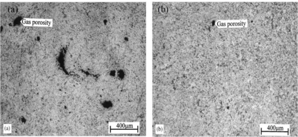
to reveal the influence of vacuum assistant, two optical microscopic images are shown in Figure 2-8. According to micrographs, microstructure of the high pressure die casting alloy (Figure 2-8.a) contains significantly higher amount of gas porosity than that in high pressure vacuum die casting alloy, proving the beneficial effect of vacuum assistant on porosity formation in high pressure die casting applications.
Figure 2-8: Optical microscopic images of Al-8% Si alloys, showing the porosity distribution in high pressure die casting (a) and high pressure vacuum die casting (b)
23 2.3 Role of Alloying Elements
Alloying elements such as Cu, Mg, Fe, Zr, Ni, Mn and Mo are traditionally added to Al-Si cast alloys for decades to modify the microstructural features, thereby increase the mechanical properties. In the following subsections, the alloying elements that commonly used in alloying and their influence on aluminum will be presented.
2.3.1 Effect of Cu Addition
It is well established that Cu addition has impact on strength and hardness of aluminum in both as cast and heat-treated conditions. It is also reported that the presence of Cu can increase the machinability of alloy due to solution strengthening potential of Cu. Shabestari et al. [30] investigated the effect of copper on mechanical properties and microstructure features. They found that in Al-Si-Mg alloys, addition of 0.2 - 0.5 % wt. Cu can significantly increase ultimate tensile strength of the alloy on T6 heat treated condition. This is attributed to the precipitation of copper bearing intermetallic phases in inter dendritic regions. On the other hand, the studies proved that addition of Cu reduces the corrosion resistance of aluminum and in specific alloys, it increases stress corrosion sensitivity [31].
2.3.2 Effect of Mg Addition
Magnesium is one of the most commonly used addition elements for aluminum alloying. Many studies indicate that Mg can increase the corrosion resistance, weldability and strengthening ability of the alloy [32,33]. In industrial applications, magnesium is generally combined with silicon in order to form hardening Mg2Si phase which can significantly improve the yield strength
(YS) and ultimate tensile strength (UTS) of the alloy in both as-cast and T6 heat treated condition. Moreover, higher level of Mg can further increase the yield strength and ultimate tensile strength.
24
Several investigations [34-35] reported that an improvement in yield strength and ultimate tensile strength is accompanied with a reduction in ductility, revealing the down side effect of Mg additions in aluminum alloys. The influence of magnesium additions on T6 heat treated yield strength in Al-Si alloys is shown in Figure 2-10.
Figure 2-10: Effect of Mg content on T6 yield strength of Al-Si alloys [36]
2.3.3 Effect of Mn Addition
It is reported that the presence of Mn element in aluminum alloy, increases the yield strength and ultimate tensile strength of the alloy due to solid solution or modification of the intermetallic phases on as cast and heat-treated conditions. In addition to that Mn helps to reduce die soldering during the casting process. Manganese is commonly combined with iron in order to modify Fe-rich phases which can reduce the harmful effect of these intermetalics on mechanical
25
properties of the alloys. On the other hand, excess amount of manganese can result in reduction of mechanical properties [37-38]
2.3.4 Effect of Fe Addition
As known well Fe is one of the main impurities and leads the formation of Fe-rich intermetallic phases in Al-Si alloys. Wang et al. [39] indicated that addition of Fe content up to 0.2% resulted in an improvement of yield strength whereas ultimate tensile strength and elongation of the alloy was slightly decreased. Although presence of Fe element can contribute yield strength, Fe-rich intermetallic phases are considered as one of the most detrimental formations for mechanical properties of Al-Si alloys. Due to their brittle features and needle-like shape, Fe intermetallic phases can result significant reduction in tensile properties, especially for elongation. Figure 2-11 illustrates an example of brittle Fe-rich intermetallic phase containing micrograph of AlSi10Mg alloy.
26 2.3.5 Effect of Zr Addition
The studies show that of addition of Zr metal into aluminum alloys results in the modification of silicon particles as well as reduction in as-cast grain size, thereby improve the strength and ductility of the alloy. Moreover, it is reported that the presence of Zr allow to form fine coherent precipitates named as Al3Zr. These particles are very stable at elevated temperature
and can resist coarsening which attributed to their high thermal stability [40].
It has been established that minor addition of Zr element (less than 0.25% wt.) in aluminum alloys can improve the tensile properties and wear resistance. Also, Shaha et al. [41] indicated that mechanical properties of aluminum alloys at elevated temperatures can be enhanced by minor additions of Zr due to thermally stable intermetallic phases and precipitates.
2.3.6 Effect of Ti Addition
In general, Ti element is used for grain refinement purposes in aluminum casting alloys. However, Majed et al [42] reveal that increasing Ti content can improve the corrosion properties. On the other hand, it is reported that the Ti content higher than 0.15% wt. can cause casting difficulties. Another study on effect of Ti showed that Ti addition up to 4% wt. can significantly increase the microhardness and wear resistance of the alloy due to precipitation of Al3Ti
compounds. In addition to that wear resistance can further increase via T5 heat treatment applications [43].
2.3.7 Effect of Mo Addition
Mo element is known as dispersoid former in Al-Si casting alloys due to its ability to form large volume of thermally stable dispersoids even when added at low levels. The literature review shows that minor additions of Mo into Al-Si-Cu-Mg casting alloys leads remarkable improvement in creep resistance due to formation of Mo containing dispersoids [44, 45]. From microstructure
27
modification aspect, a significant impact of Mo elements on grain size was not reported. However, it is found that Mo addition in Al-Si casting alloys pushed down to presence of brittle β-Al5FeSi intermetallic phases whereas it promoted the formation of blocky Al-(Fe,Mo)-Si compounds, thus significantly improve the tensile elongation [45].
Figure 2-12: TEM micrograph of Al-(Fe,Mo)-Si dispersoids in interdendritic regions (a) and EDS spectrum of the dispersoids (b) [45].
According to another study, it is found that the addition of 0.3% Mo into aluminum - titanium cast alloys results enhancement in hardness and flow stress. In addition to that Mo helps to improve the surface quality of the alloy [46].
2.3.8 Effect of V Addition
Although many studies were carried out to reveal the influence of transition metals additions on mechanical properties and microstructural features, a fully understanding of the indivudual effect of V addition is not actualized yet. It is established that V element enhance the alloy performance by forming Al3V and Al10 compounds which is indeed originated from master
28
and Mo. It is well known that V, Zr and Ti elements have very low diffusivity and solubility in aluminum, form thermally intermetallic phases, thereby help to maintain mechanical properties at elevated temperatures. In addition, Al-Si casting alloys contain a certain amount of Fe impurities which lead the formation of needle-like Fe-rich intermetallic phases. These intermetallic phases are known as detrimental for mechanical properties, particularly for elongation. In this regard, a study proved that additions of V and Zr elements can modify needle-like intermetallic phases, thereby improve the mechanical properties in as-cast condition. [40, 46].
29
REFERENCES
[1] John E. Hatch, Aluminum: Properties and Physical Metallurgy, American Society for Metals, Metals Park, Ohio, USA, 1984, p. 339.
[2] Zhang, D. and L. Zheng, The quench sensitivity of cast Al-7 wt pct Si 0.4 wt pct Mg alloy. Metallurgical and Materials Transactions A, 1996. 27(12): p. 3983-3991.
[3] J.L. Jorstad, "Hypereutectic Al-Si Casting Alloys: 25 Years, What's Next?", Silver Anniversary Paper, AFS Transactions, Vol. 104, 1996, pp. 669-671.
[4] Shaha, S.K., PhD. Thesis: Development and Characterization of Cast Modified Al-Si-Cu Alloys for Heat Resistant Power Train Applications, 2015.
[5] Lee, F., J. Major, and F. Samuel, Effect of silicon particles on the fatigue crack growth characteristics of Al-12 Wt Pct Si-0.35 Wt Pct Mg-(0 to 0.02) Wt Pct Sr casting alloys. Metallurgical and Materials Transactions A, 1995. 26(6): p. 1553- 1570.
[6] Hoskin, G., J. Provan, and J. Gruzleski, The in-situ fatigue testing of a cast aluminum-silicon alloy. Theoretical and applied fracture mechanics, 1988. 10(1): p. 27-41.
[7] C. Kammer, Aluminum Handbook, Vol. 1: Fundamentals and Materials, Aluminium-Verlag, Inc., 1999.
[8] M. Warmuzek, Aluminum-silicon casting alloys, Ohio, USA: ASM International, 2004. [9] M. Lebyodkin, A. Deschamps and Y. Bréchet, "Influence of Second-Phase Morphology on Mechanical and Fracture Properties of Al-Si Alloys", Materials Science and Engineering, Vols A234-236, 1997, pp. 481-484.
![Figure 2-10: Effect of Mg content on T6 yield strength of Al-Si alloys [36]](https://thumb-eu.123doks.com/thumbv2/123doknet/7474756.223104/51.918.218.705.293.683/figure-effect-mg-content-yield-strength-al-alloys.webp)