Rating Optimization of Three Phase Series Hybrid Power
Filter for Power Quality Compensation and Renewable
Energy Integration
by
Muftah ABUZIED
THESIS PRESENTED TO ÉCOLE DE TECHNOLOGIE SUPÉRIEURE
IN PARTIAL FULFILLMENT FOR A MASTER’S DEGREE WITH THESIS
IN ELECTRICAL ENGINEERING
M.A.Sc
MONTREAL, June 07, 2018
ÉCOLE DE TECHNOLOGIE SUPÉRIEURE
UNIVERSITÉ DU QUÉBEC
This Creative Commons licence allows readers to download this work and share it with others as long as the author is credited. The content of this work can’t be modified in any way or used commercially.
BOARD OF EXAMINERS
THIS THESIS HAS BEEN EVALUATED BY THE FOLLOWING BOARD OF EXAMINERS
Mr. Kamal Al-Haddad, Thesis Supervisor
Department of Electrical Engineering, École de technologie supérieure
Mr. Abdelhamid Hamadi, Thesis Co-supervisor
Department of Electrical Engineering, École de technologie supérieure
Mme Lyne Woodward, President of the Board of Examiners
Department of Electrical Engineerig, École de technologie supérieure
Mr. Pierre Jean Lagacé, Member of the jury
Department of Electrical Engineerig, École de technologie supérieure
THIS THESIS WAS PRENSENTED AND DEFENDED
IN THE PRESENCE OF A BOARD OF EXAMINERS AND PUBLIC MONTREAL, MAY 14, 2018
ACKNOWLEDGMENT
I would like to express my sincere gratitude to my thesis supervisor, Professor Kamal Al-Haddad, for the opportunity he has given me to carry out my work in this field. Without his thrust, excellent technical guidance, patience, and moral support, my research would not have been successful.
I would also like to express my profound thanks to my thesis Co-supevisor, Mr. Abdelhamid Hamadi, for his continuous advice, technical supervision and all his support. Undoubtedly, he was the most influential persons during my master studies and I hope the tie that we established during the time that this research project has being carried out will continue for many years to come.
I would like to acknowledge the Higher Institute for Comprehensive Professions-Tarhounah and Libyan Ministry of Education for providing me the opportunity to pursue my Master study and recommending me for scholarships offered.
Special thanks go to my parents, and friends that my success in carrying out and completion of this project would certainly not have been possible without their generous support, the best thanks go to all my friends at ETS.
Thanks to my lovely sons who give me the will and power to go beyond difficulties and without them this work would not have been completed easily, I dedicate this thesis to my sweet sons Mohamed and Ilyas.
Finally, I wish to give my wholehearted thanks to my beloved wife for her support, encouragements, and patience while lifting much of the burden of life during the final stages of this thesis.
ÉVALUATION DE L’OPTIMISATION DU FILTRE À ÉNERGIE HYBRIDE SÉRIE TRIPHASÉE POUR LA COMPENSATION DE LA QUALITÉ DE L'ÉNERGIE ET
L'INTÉGRATION DE L'ÉNERGIE RENOUVELABLE
Muftah ABUZIED
RÉSUMÉ
Les filtres séries hybrides et les filtres passifs shunt améliorent considérablement la qualité de l'énergie et assurent une alimentation en tension fiable en atténuant ou en éliminant les problèmes tels que les distorsions de tension, les creux, les surtensions et les déséquilibres. Ils peuvent également compenser les problèmes de courant liés aux charges linéaires et non linéaires, telles que, les courants harmoniques et la puissance réactive. Dans cette étude de thèse, un filtre de puissance série hybride triphasé fut conçu pour la compensation de la qualité de l'énergie.
Une recherche majeure dans cette thèse concerne une approche permettant de compenser simultanément la puissance réactive en supprimant un convertisseur TCR proposé dans l’article publié qui a un impact sur la réduction du coût du filtre série hybride triphasé. Une comparaison de deux approches de la conception du filtre passif pour évaluer l'impact sur le dimensionnement du filtre est étudiée et des résultats ont été validés par simulation.
Le filtre série hybride (HSeAF) est très utilisé en tant que compensateur de puissance basé sur l'électronique de puissance car il s’est avéré très efficace. Sans la partie active du HSeAF, le filtre passif shunt est incapable de résoudre seul les problèmes de tension en tant que restaurateur de tension dynamique. Un système à trois phases HSeAF conventionnel comprend trois transformateurs d'isolement en série connectés à un convertisseur triphasé partageant un bus de liaison CC commun. Il est contrôlé comme une source de tension variable similaire à un filtre de puissance actif shunt, ce dernier étant réglé pour les fréquences harmoniques et installé pour créer un chemin alternatif pour les harmoniques de courant de charge. La littérature existante se concentre sur l'utilisation de filtres de puissance actifs hybrides pour compenser uniquement les problèmes de courant de charge, en raison de la complexité et du coût des dispositifs. La présente recherche cherche plutôt à optimiser les ressources disponibles afin d'améliorer l'efficacité du produit et de réduire les coûts globaux.
Une approche permet également une utilisation plus intelligente du filtre passif shunt en vue de réduire le dimensionnement du filtre actif série et une réduction globale des coûts. Les simulations MATLAB montrent que le SHPF triphasé est capable de résoudre simultanément les problèmes de tension et de charger les problèmes de courant.
Mots-clés: Filtre actif de puissance, Compensation d'harmoniques de courant, Filtre série
RATING OPTIMIZATION OF THREE PHASE SERIES HYBRID POWER FILTER FOR POWER QUALITY COMPENSATION AND RENEWABLE ENERGY
INTEGRATION
Muftah ABUZIED
ABSTRACT
Hybrid series active filters and shunt passive filter can significantly improve power quality and ensure a reliable voltage supply to the load through mitigating or eliminating issues such as voltage distortions, sags, swells, and unbalances. They can also compensate current problems related to linear and non-linear loads, such as load reactive power, current harmonics
In this thesis study, a 3-phase hybrid series power filter for power quality compensation is used for current harmonic, reactive power compensation, unbalance/sag/swell grid voltage compensation. A major research in this thesis concerns an approach to compensate simultaneously a reactive power by removing a TCR converter proposed in the paper published which has an impact on the reduction of the cost of the three phases series hybrid filter. Other research concerns the comparison of two approaches of the design of the passive filter to evaluate the impact on the series active filter rating.
The hybrid series active filter (HSeAF) has gained in popularity as a highly efficient power electronics-based active power compensator. Without the active portion of the HSeAF, a shunt passive filter is unable to resolve voltage problems on its own as a dynamic voltage restorer. A conventional HSeAF 3-phase system comprises three series isolation transformers connected to a 3-phase converter sharing a common DC link bus. It is controlled as a variable voltage source similar to a shunt active power filter, the latter which is tuned for harmonic frequencies and installed to create an alternative path for load current harmonics. The existing literature focuses on using hybrid active power filters to compensate for load current issues only, due to the complexity and expense of the devices. The present research looks instead at optimizing available resources in order to enhance product efficiency and reduce overall costs. Also an approach provides smarter use of the shunt passive filter; along with a reduced series active filter rating and an overall reduction in cost. MATLAB simulations show that the 3-phase SHPF is able to simultaneously resolve voltage problems and load current issues.
Keywords: Active power filter, Current harmonic compensation, Series Hybrid filter, Power
TABLE OF CONTENTS
Page
INTRODUCTION ...1
CHAPTER 1 LITERATURE REVIEW ...5
1.1 Introduction ...5 1.2 Types of Loads ...6 1.2.1 Balanced Loads ... 6 1.2.2 Unbalanced Loads ... 6 1.2.3 Linear Loads ... 6 1.2.4 Non-linear Loads ... 7
1.3 Power Quality Solution ...7
1.3.1 Passive Filter (PF) ... 8
1.3.2 Active Filter (AF) ... 9
1.4 Series Active Filter (SeAF) ...9
1.4.1.1 Hybrid Filter (Series Active and Passive Filter) ... 13
1.4.1.2 Unified Power Quality Conditioner ... 14
1.5 Modeling of Series Hybrid Power Filter (SHPF) ...15
1.5.1 Configuration of Series Hybrid Power Filters (SHPFs) ... 16
1.5.2 Novel HSAF for Power Quality Compensation ... 17
1.5.3 New HSAF Configuration to Offset Reactive Power, Current/Voltage Harmonics, and Voltage Swell/Sag ... 19
1.5.4 SHAPF for Mitigating Voltage Unbalance and Harmonics under Unbalanced Non-Sinusoidal Supply Conditions ... 21
1.5.5 Improving Power Quality Through a Photovoltaic-based 3-Phase 4-Wire SHAPF ... 23
1.5.6 Enhancing Power Quality Through the Use of Hybrid Series Active Power Compensator ... 26
1.5.7 Enhanced Strategy to Offset Unbalanced Loads in HSAFs ... 28
1.6 Research Objectives ...30
1.7 Conclusion ...30
CHAPTER 2 SLIDING MODE CONTROL WITH SERIES HYBRID POWER FILTER AND REDUCING SIZE WITH DIFFERENT PASSIVE FILTER DESIGN ...33
2.1 Introduction ...33
2.2 System Configurations ...34
2.2.1 Modeling of 3-Phase HSPF with Bridge Diode ... 34
2.2.2 Control Strategy of 3-Phase SHAF ... 35
2.2.3 Passive filter design ... 40
2.3 First method of passive filter design ...42
2.4.1.1 Second method to design passive filter by minimum cost of
resonant filter ... 62
2.4.2 Simulation Results ... 66
2.5 Conclusion ...73
CHAPTER 3 THREE-PHASE HYBRID SERIES ACTIVE FILTER WITHOUT BRIDGE DIODE ...75
3.1 Introduction ...75
3.2 System Configurations ...76
3.2.1 Modeling of 3-Phase HSAF without Bridge Diode ... 76
3.2.2 Control Strategy of 3-Phase HSAF ... 77
3.2.2.1 Control of HSAF Active Part ... 77
3.2.2.2 Series APF Reference Voltage Signal Generation ... 80
3.2.3 Simulation Results ... 81
3.2.3.1 Current harmonic compensation ... 81
3.2.3.2 Load variation ... 85
3.2.3.3 Unbalanced voltage ... 86
3.2.3.4 Sag and swell voltage... 87
3.3 Conclusion ...88
CHAPTER 4 THREE-PHASE HYBRID SERIES ACTIVE FILTER INTEGRATING RENEWABLE ENERGY CONNECTED TO THE GRID...91
4.1 Introduction ...91
4.2 Solar Photovoltaic (PV) System ...92
4.2.1 Boost converter modeling ... 93
4.2.2 PV solar design ... 95
4.2.3 Solar panels arrangement ... 96
4.2.4 Energy storage system design ... 96
4.2.5 Maximum Power Point Tracking (MPPT) Algorithm ... 98
4.3 System Configurations ...100
4.3.1 Modeling of 3-Phase HSAF with PV solar ... 100
4.3.2 Control Strategy of 3-Phase HSAF ... 101
4.3.3 Simulation results... 102
4.3.3.1 Current harmonic compensation ... 102
4.3.3.2 Grid ON/OFF ... 106
4.4 Conclusion ...107
CONCLUSION ...109
RECOMMENDATIONS ...111
LIST OF TABLES
Page
Table 2.1 System Configuration parameters ...41
Table 2.2 System parameters with minimum cost of design passive filter ...43
Table 2.3 Power parameters and THD’s during steady state ...48
Table 2.4 Power parameters and THDs during load variation ...54
Table 2.5 Power parameters used during sag and swell voltage compensation ...56
Table 2.6 Power parameters and THDs during unbalanced voltage ...60
Table 2.7 Parameters of the passive filter in the second method ...66
Table 2.8 Power parameters and THDs during current harmonic compensation ...70
Table 3.1 Power parameters and THD’s during steady state ...85
Table 4.1 Solar panel characteristics ...97
LIST OF FIGURES
Page
Figure 1.1 Passive filter ...9
Figure 1.2 Functionality schematics of series compensation ...11
Figure 1.3 Hybrid filter ...14
Figure 1.4 A typical unified Power quality conditioner resolving power quality issues. ...15
Figure 1.5 Hybrid series power filter configuration ...16
Figure 1.6 Hybrid series active filter with non-linear loads ...17
Figure 1.7 Control scheme of active power filter ...19
Figure 1.8 Proposed series hybrid power filter configuration ...20
Figure 1.9 Circuit configuration of the SHAPF ...22
Figure 1.10 TCR control scheme for SHAPF ...22
Figure 1.11 PV-based SeAF with ShAF topology ...24
Figure 1.12 Proposed controller of PV-based SeAF ...25
Figure 1.13 THSeAF connected to the single-phase system ...27
Figure 1.14 Control scheme of Hybrid Series Active Power Compensator ...28
Figure 1.15 Diagram for simulation ...29
Figure 1.16 Proposed control for series active filter ...30
Figure 2.1 Series hybrid active filter with nonlinear load and linear load ...35
Figure 2.2 Control scheme for the active filter ...40
Figure 2.3 a) Equivalent Passive filter, b) Impedance representation versus frequency ...41
Figure 2.5 THDs during steady state ...46
Figure 2.6 Three-phase powers flow with steady state ...47
Figure 2.7 Leading voltage ...49
Figure 2.8 Lagging voltage ...50
Figure 2.9 Phasor diagram (a) leading voltage (b) lagging voltage ...51
Figure 2.10 Simulation results during load variation ...52
Figure 2.11 Results of the THD during Load Variation. ...53
Figure 2.12 System behavior during sag and swell voltage compensation ...55
Figure 2.13 Power flow with sag and swell voltage ...56
Figure 2.14 System behavior during unbalanced compensation ...58
Figure 2.15 Power flow with unbalanced voltage ...59
Figure 2.16 Power flow with passive filter variation ...61
Figure 2.17 Single-phase diagram of a simplified network with filters ...64
Figure 2.18 Results of the current harmonics compensation during the steady state....68
Figure 2.19 THD during current harmonics compensation ...69
Figure 2.20 Leading voltage ...71
Figure 2.21 Lagging voltage ...72
Figure 2.22 Phasor diagram (a) lagging voltage (b) leading voltage ...72
Figure 3.1 Hybrid series active filter with non-linear loads ...77
Figure 3.2 Control scheme of the active power filter ...80
Figure 3.3 Steady state simulation results of the active power filter control scheme ...82
Figure 3.4 Power flow with the steady state ...83
Figure 3.5 THD during current harmonics compensation ...84
Figure 3.7 Results of the system during a source voltage unbalance ...87
Figure 3.8 Results of the system during sag/swell source voltage ...88
Figure 4.1 Scheme of the PV solar panels based energy supply system ...92
Figure 4.2 Post regulator boost converter ...93
Figure 4.3 (a) Current control loop of the boost converter, (b) Control scheme of the boost converter ...94
Figure 4.4 Characteristics of the PV solar ...99
Figure 4.5 Perturb and observe MPPT algorithm ...99
Figure 4.6 Hybrid series active filter with PV solar ...101
Figure 4.7 Control scheme of the active power filter ...102
Figure 4.8 Simulation results of the system in steady state ...103
Figure 4.9 Power flow with the steady state ...104
Figure 4.10 THD during current harmonics compensation ...105
LIST OF ABREVIATIONS
3P4W Three-phase four-wire system 3P3W Three-phase three-wire system AC Alternating current
AFs Active Filters APFs Active power filters DC Direct current
DVR Dynamic voltage restorer ESs Energy Sources
FACTS Flexible AC transmission systems FLC Fuzzy logical controller
HPF High Pass Filter
HSAF Hybrid Series Active Filter HSAPF Hybrid Series Active Power Filter HSPF Hybrid Series Power Filter
LPF Low Pass Filter
MPPT Maximum Power Point Tracking PCC Point of common coupling
PF Passive Filter
PLL Phase Locked Loop
PMSG Permanent Magnetic Synchronous Generator
PV Solar Photovoltaics Panel SAPF Series Active Power Filter
SCIG Squirrel Cage Induction Generator SeAF Series Active Filter
SeAPF Series Active Power Filter SFR Synchronous Reference Frame SG Synchronous Generator SHAPF Series Hybrid Active Power Filter SHPF Series Hybrid Power Filter
SPF Series Power Filter TCR Thyristor Control Reactor UPS Uninterruptible Power Supply UPQC Unified Power Quality Conditioner VSI Voltage Source Inverter
LIST OF SYMBOLS
ω Angular frequency
δ Power angle between source and load voltages
φ Phase angle between source current w.r.t. to source voltage Cdc DC link capacitor
Cf Ripple filter capacitor
D Distortion power
f System frequency
Fh Respective harmonic’s order shunt passive filter G Gain proportional to current harmonics
h Harmonic order
Hz Hertz
HP Horse power
iS Source current
iL Load current
ISh Source harmonic current
KP Proportional gain Ki Integral gain L Inductance Ω Ohm P Active power Q Reactive power
r or R Resistance s Second
S Apparent power
TS Discrete sampling time
V Voltage W Watt Z Impedance
Multiple and sub-multiple of SI unities M: 106= 1 000 000 mega k: 103= 1 000 kilo m: 10-3=0.001 mili μ: 10-6= 0.000 001 micro Mathematical symbols Bold (V or v) Matrix
Asterisk (V*) Reference signal
Hat ( ) Measured value
V rms value
INTRODUCTION
Just prior to the start of the twentieth century, electrical power underwent a series of dramatic changes. In 1882, customers received the first transmission of electric power with direct current (DC). However, maintaining a steady voltage over long-distance transmissions proved challenging to the emerging industry, so engineers devised the alternating current (AC) along with 3-phase power systems. Then, to better improve power quality, a hybrid series filter was introduced because of its low rating and ease of control.
The twentieth century saw an expansion of the electrical industry, in large part due to massive government investment. At the same time, there was a substantial rise in the generation of power from renewable sources. The turn towards sustainable energy was prompted by a widespread desire by consumers and governments to scale back exploitation of natural resources as well as to decrease harmful emissions. These renewable energies were dubbed ‘green’ and refer to natural processes that can be harnessed for energy but with few to no adverse environmental impacts (Javadi, 2016).
However, the industry experienced a broad range of challenges in attempting to harvest electrical power from alternative resources. For instance, most of the sources cannot generate constant power because of their natural characteristics (e.g., solar energy only being able to be harvested during sunny days) and unpredictable behaviour (e.g., the wind). Hence, they have reduced commercial efficiency. Moreover, most alternative sources need highly advanced and costly components and controllers, again making them unattractive to users. Despite these challenges, governments have continued to support alternative suppliers with the aim of making a ‘greener’ future. Sensing the trend, some commercial entities are slowly coming on board and shifting their focus to generating electricity from resources that are less harmful than oil and gas.
Against this backdrop, the ideal power system should be flexible, have the ability to control energy management, and be able to manage power flow from several sources at once. Current power systems have not yet achieved this ideal, but they could come closer with the adoption
of the smart grid concept. Under such a concept, the power system’s infrastructures would have to be updated or modified to handle greater power supplies from the system’s distributed sources. Meanwhile, the components and smart devices would also have to be updated or modified to recognize different scenarios and function on an instinctive level.
Current Harmonics: This type of harmonics comprises components that include frequencies
other than the system’s nominal frequency (e.g., 50 or 60 Hz). Such components with different amplitudes can become sources of several types of disorders in electrical systems, such as voltage distortions when passing through an inductance or transformer, decreased efficiency, extreme losses in lines and electrical components, acoustic noises in electro-magnetic devices, and the production of a neutral current (Javadi, 2016). Thus, the increase in harmonic pollution originating in non-linear loads can have a negative impact on the power system and equipment. To curtail current levels of disturbance, IEEE standards 519 and 1459 were introduced (IEEE Recommended Practices and Requirements for Harmonic Control in Electrical Power Systems, 1993; IEEE Standard Definitions for the Measurement of Electric Power Quantities Under Sinusoidal, Nonsinusoidal, Balanced, or Unbalanced Conditions, 2010). As well, the International Electro-technical Commission (IEC) released some technical reports to gauge the connection between non-linear loads and power plants (International Electro technical Commission [IEC], 2009-04).
Reactive Power: Voltages and currents are sinusoidal waveforms in the AC systems.
However, power calculation is difficult if the waveforms do not align. The outcome of such misalignments is apparent power (S), designated as the cross-operation of the two waves. It has two distinct components: one moves from the source to the load and works at the load, while the other component cannot perform useful work at the load because of delays between voltage and current (phase angle). This section is referred to as reactive power. It essentially lowers power flow efficiency in terms of power consumed vs. installed capacity.
Voltage Unbalance: An unbalance occurs when the three phases of a 3P3W or 3P4W system
do not share the same voltage magnitude and phase shift precisely. Because voltage unbalance can damage motors and transformers, the IEEE std 1159 (IEEE Recommended Practice for
Monitoring Electric Power Quality, 1995) has instituted strict rules for power operators (Javadi, 2016).
Voltage Sags: The IEEE’s Standard Recommended Practice for Monitoring Electric Power
Quality (1995), states that voltage sag is a decrease in voltage of a relatively short duration, or specifically “a decrease between 0.1 and 0.9 p.u in rms voltage for duration of 0.5 cycles to 1 min.” Voltage sags can occur as a result of load changes or motor start-up, as induction motors can consume up to ten times their nominal rated current at the start-up phase.
Voltage Swells: These are short duration increases in rms voltage from 0.5 cycles to 1 min.
The magnitude usually ranges between 1.1 and 1.8 p.u. Swells occur less frequently than sags and are often associated with system fault conditions. Cases during which swells can occur include switching on a large capacitor bank or switching off a sizeable load.
In this section of the thesis, we briefly discussed the significance of compensating for various phenomena that impact power quality. We concluded the chapter by highlighting the contribution of this project regarding the improvement of power quality enhancement. The first main contribution is the integration in the control technique of the compensation of the reactive power which helps to remove the TCR converter used in the published research.
The second contribution is the design of passive filters by two different techniques with the objectives to analyse the performances and to reduce the rating of the active filter.
The third one concerns the modification of the configuration by removing the bridge, testing the regulation of the dc bus voltage by the active filter and the different perturbations.
The configuration of the HSPF proposed integrate a PV solar and the battery in the DC side of the active filter to be acted during grid OFF operation in order to maintain uninterruptible power supply to the load.
In the first chapter, the literature review for different harmonics mitigation techniques, series active filter topologies and control is presented. The latest advanced configurations and their respective control are included.
The second chapter analyzes the modeling of a three phase series hybrid power filter with bridge diode to regulate dc bus voltage, using sliding mode control design to improve power quality (sag/swell/unbalance voltage, current harmonics, and reactive power compensation). In addition, this chapter covers a passive filter design, and studies the stability of the control system.
The third chapter contains a modeling of a three phase series hybrid power filter with dc bus voltage regulated with itself using nonlinear control design for compensating current harmonics, reactive power and unbalance voltage.
The final and fourth chapter covers the application of the PV solar through three phase series hybrid power filter method, and presentation the simulation results, which allows the validation of the proposed grid on/off operation scheme.
CHAPTER 1 LITERATURE REVIEW 1.1 Introduction
This chapter describes hybrid series power filters (HSPFs) and provides some relevant background information on their control as well as on synchronized passive filters. In addition, the chapter provides an overview of the most recent advances in power quality enhancer devices. After defining HSPF and the filtering application for power quality improvement, the chapter discusses the advantages of an intelligently controlled power system that uses renewable energy sources. To overcome any issues related to this advancement in technology, alternating current (AC) transmission systems along with 3-phase power systems were developed. The following power compensation approaches were later developed to boost power quality:
• Harmonic voltage compensation; • Harmonic current compensation; • Sag and swell voltage compensation; • Neutral current compensation; • Reactive power compensation; • Unbalanced voltage compensation.
A variety of HSAF approaches have been developed over the years, each with its own particular advantages and disadvantages. For instance, a few of the approaches are meant to resolve power quality issues, such as voltage and current harmonics, load reactive power, and voltage sag and swell. An additional parameter that is based on HSAF is the level of reactive power required. Another factor is the price of the materials and equipment needed for reactive power. These parameters and factors help to determine which approach is best suited for which projects. The methods can also differ in relation to the sizing of the HSAF elements.
There has been a recent surge in the use of renewable energy sources for power generation. Therefore, integrating an HSPF could help to reduce the usage of traditional resources, which
will consequently reduce pollution emissions. Renewable energy sources are popularly referred to as ‘green’ energy and include natural (i.e., non-processed) sources that can generate energy with little to no residual pollution. Despite their benefits to the environment, however, green energies bring with them a whole host of new problems, chief among which is their lack of constancy due to their unique characteristics (e.g., solar energy being reliant on sunny days) and oftentimes unexpected behaviour (wind energy being reliant on windy weather). Green sources also have generally low commercial efficiency. Thus, a hybrid series could be applied as an uninterruptible power supply (UPS) to resolve these issues.
1.2 Types of Loads
Based on the network system(s) being utilized, there is a wide variety of load types, such as linear and non-linear loads. Each type of load likewise has subtypes, such as balanced and unbalanced loads.
1.2.1 Balanced Loads
Load balancing is intended to store the load information of peer nodes in several directories, which then can schedule reassignments of virtual servers to achieve better balance, if needed. The distributed load balancing problem can then be reduced to a centralized problem at each directory.
1.2.2 Unbalanced Loads
An unbalanced 3-phase load can be defined as a load which is unequally distributed across three phases. To rate as a 3-phase load, the highest single phase load must be multiplied by 3. An unbalanced load can lead to unequal phase-to-phase and phase-to-neutral voltages.
A linear load is the one which exhibits steady impedance to the supply voltage, causing the current wave shape to change directly proportional to the supply voltage. Constant impedance shows a sinusoidal current waveform if the supply voltage waveform is sinusoidal. Examples of linear loads include motors, incandescent lighting, and resistance heating (Debasish and Rakesh, 2013).
1.2.4 Non-linear Loads
In contrast to a linear load, a non-linear load exhibits changing impedance to the applied voltage, which means that the current waveform can not alter based on voltage waveform. The result is a non-sinusoidal current waveform. Furthermore, non-linear loads offer large impedance at some sections of the voltage waveform. This impedance is reduced when the voltage reaches peak value. When low impedance occurs, the current experiences a sharp rise, whereas when the impedance value increases, the current drops. Thus, as the voltage and the current waveform are not in synch, they are considered non-linear. Examples include drives with altering speeds, loads with diode-capacitor power supplies, and uninterruptible power supply. These types of loads draw short pulse currents during the crest of the line voltage. Moreover, the non-sinusoidal current pulses inject unpredictable reflective currents into the power distribution system, which leads to the current functioning at frequencies different from the primal frequency (Debasish and Rakesh, 2013).
1.3 Power Quality Solution
Recent advances in power electronics have seen active filters (AFs) gaining in popularity. On a commercial basis, shunt active filters have been available for small and medium voltage applications. Shunt AFs have several advantages compared to traditional passive filters. For instance, they are independent of the system parameter state, do not require tuning, and respond well to load variations. Additionally, the compensation efficiency of shunt AFs is not dependent on external parameters. They have near total control and can carry out every type of modification without the need to change the hardware (Javadi, 2016).
Given the recent technological improvements in the industry, along with the decrease in the output cost of power electronic converters, the use of active compensators is inevitable.
Furthermore, the increasing popularity of ‘smart’ grids has confirmed the application of compensators to improve power quality compared to more traditional passive filters. Furthermore, as they have topologies similar to FACTS devices, the industry is satisfied that they will be reliable in critical operating states. The following section presents an overview of the various categories of filters (Javadi, 2016).
1.3.1 Passive Filter (PF)
Passive filters (PFs) can be generated easily and at a low cost from basic electrical components (e.g., resistors, capacitors, and inductors), making them attractive to industry. At the same time, traditional filters comprised of passive components can significantly improve the current and voltage harmonics of power systems. However, they can have considerable drawbacks; they require load and system parameters (e.g., impedances) to be meshed properly. Therefore, when installed, they operate through defined system specifications and are not readily adaptable to load differences or changes in those specifications. This means that although under special conditions they might initially improve power quality, they could also worsen it later by not operating as predicted. Hence, they need to be re-tuned occasionally to maintain efficiency, as there are no controls on their process state (Javadi, 2016).
PFs have been utilized since the introduction of the AC supply system. Their main purpose is to improve the power quality of the system. Typical characteristics of PFs include lossless reactive elements (capacitors and inductors) and dependence on the source’s impedance value. Furthermore, PFs can be applied to improve the voltage, dynamics, steady-state, transit, and angle stabilities. The source impedance at the network frequency should be relatively low to prevent the fundamental voltage from crossing the limits. Figure.1.1 shows a passive filter. Its advantages are: improving grid stability, improving load balancing in instances of several parallel circuits, correcting the power factor, regulating voltage, reducing losses and voltage drops and reducing neutral current in the grid. Also its disadvantages are: Reducing line impedance (which coordinates increase in harmonics from the load to the source) and potentially producing subharmonic-type resonance between line impedance and series capacitor.
Figure 1.1 Passive filter
1.3.2 Active Filter (AF)
Active filters (AFs) are derived from the notion of compensating reactive power as well as the harmonic currents created by non-linear loads, which are caused by semi-conductor switches such as converters, diode bridges and thyristors bridges. They are compensated by being injected with the same magnitude and amplitude in the opposite direction. Harmonic components of non-linear loads are usually used as references to AF currents. Thus, AFs have emerged as a viable solution in harmonics and reactive power compensation (Javadi, 2016). Active filters are created from a range of semiconductors operating as switches. The main element of an AF is its converter, which, in case of the control side, may depend on the voltage or current source. A continuous voltage source type capacitor is one which opposes the voltage variations, whereas a current source type converter is an inductance which opposes current variations. Different kinds of active filters include series AFs, shunt AFs, and hybrid AFs (Javadi, 2016).
1.4 Series Active Filter (SeAF)
Series active filters (SeAFs) were developed to introduce a voltage in series with the circuit, with the intention of isolating the source from the load. In particular, they were developed to
offset the disadvantages of passive filters, which are quite costly and overall inadequate. At the same time, PFs are difficult to install, as a precise estimate of system parameters is necessary prior to installation, and such an estimate can take immense time and effort. Furthermore, parameters change as the power grid develops, so PFs likewise need to be altered to reflect these changes. This serves to decrease the efficiency of PFs while increasing related costs.
Shunt AFs are often used instead of passive filters, but they are typically restricted to correcting the power factor and compensating current harmonic pollution produced by non-linear loads. To resolve issues around power, line conditioning systems can be used for repressing and/or counteracting power system disturbances. Series active filters and dynamic voltage restorers (DVRs) can be utilized to compensate current issues and reduce voltage distortions. However, given the complexity of series active compensators compared to conventional shunt AFs, the use of these devices is generally confined to applications where PQ requirements are relatively strict (Javadi, 2016).
Along with issues related to current to compensate current, it is important to safeguard critical loads and PCCs from voltage distortions, sags, and swells. To accomplish this, a dynamic voltage restorer can be used. DVRs and SAFs divide similar topologies that are comparatively complex in parts because of the isolation transformer needed to couple to the grid. Although providing reasonably good isolation for the compensating system, the transformer is costly and can cause a range of undesirable performance issues, such as hysteresis phenomena and electrical losses (Javadi, 2016). The SeAF model is shown in Figure 1.2.
Figure 1.2 Functionality schematics of series compensation
The idea of series active compensation was introduced near the end of the 1980s to enable voltage regulators to operate in sensitive loads (Gyugyi, 1979). Series-connected filters protect users from insufficient supply-voltage quality, and they should also ensure a sinusoidal balanced voltage on the load side, even with perturbations in the source voltage. Typical perturbations include harmonic distortion, sags and swells, and unbalance; they can also include disturbances in the current load, such as distortion by harmonics, step changes, unbalance, and distortion by harmonics. Through increasing usage of this method, it was found to have the ability to isolate current harmonics of a voltage-fed type of non-linear load (VSC) from the power system. In most instances, and in order to compensate load current harmonics, series active power filters (which are a controllable voltage source) must function together with shunt passive filters. However, if passive (L-C) filters are connected in parallel, the series active power filter functions as a harmonic isolator, enabling the load current harmonics to
circulate primarily through the passive filter instead of the power system (Javadi et Al-Haddad, 2011).
This method is extremely useful for compensating voltage unbalances as well as sags and swells from the AC supply; it is also useful for low-power applications. As equally important, it is a cost-effective alternative to UPS, as no energy storage on the DC bus is needed, so the overall sizing of the components is relatively small.
Furthermore, since the efficiency of active compensators makes them attractive for industrial smart grids application, the compensators could potentially help to increase the amount of renewable energy that enters the grid (Singh, Al-Haddad and Chandra, 1999). The recent wave of novel low-cost power electronics has made active filters desirable to the industry. As an affordable solution, active filters could prove to be indispensable in the future for boosting and streamlining the power quality of grids with smart and adaptive devices. Currently, shunt active filters (SAF) are being used at the distribution level in instances where passive filters have proven inefficient, unsafe, and imprecise.
For resolving current and voltage issues simultaneously, there is a relatively efficient but expensive solution known as the unified power quality conditioner (UPQC) (Brenna, Faranda and Tironi, 2009; Khadkikar and Chandra, 2008). For regulating problems around voltages and currents as well as to improve the quality of the energy produced, the UPQC uses a series active filter in combination with a shunt. The shunt active portion compensates current harmonics and adjusts the power factor of a non-linear load, whereas the series active portion gets rid of voltage distortions and monitors the 3-phase voltage at the PCC (Khadkikar and Chandra, 2009; 2011). This approach has been shown to be a viable solution for enhancing power quality, with several different topologies being developed (e.g., the shunt active filter connected in the right - or left- side of the series active part). However, the overall complexity of the system’s components makes it relatively unaffordable for most commercial and residential users (Javadi, 2016). Despite its success in practice, the core issue with this particular configuration is the non-isolation of the DC bus bar and 3-phase power system.
1.4.1.1 Hybrid Filter (Series Active and Passive Filter)
Today’s electrical equipment makes stringent demands on supply voltage stability and quality. However, at the same time, power networks need to be free from harmonics and related electrical issues. Getting rid of unwanted harmonics in the system and avoiding resonance issues are some of the main problems that emerge when boosting power quality. Overcoming these problems can bring numerous benefits, including a higher power factor, greater voltage stability, and decreased network loss. Purging the network of problems also has the added benefit of reducing stress on equipment, which then increases its life-time. Longer equipment life means reduced overall costs related to replacement of worn-out equipment (Javadi, 2016). To benefit from the advantages of both passive and active filters, several different types of hybrid filters have been developed. Within the context of this present study, a series active filter in parallel with a passive filter bank configuration is most appropriate. This hybrid will be studied in detail, with an aim to resolve current issues while taking into account the restoration of load supply (Javadi, 2016). This type of filter has benefits both in the simplicity of the passive division and the high dynamic provided by the active portion. The combination of benefits thus offers higher VAR compensation than active or passive filters.
A hybrid filter is based on an approach that combines an active and passive filter. As mentioned previously, passive power filters in power system applications can have issues around source impedance that can detrimentally affect the filtering process and system resonance. These issues can, however, be resolved or at least mitigated by adding a combination of active and passive power filters. Harmonics that are generated from non-linear loads constantly change frequency and frequency components. As they consist of passive and active power filters, hybrids can supply ideal harmonic compensation for dynamic non-linear loads as well as repress series and parallel resonances. Hybrid filters can also filter more rows of harmonics. As the hybrid series filter compensation is the subject of the current research work, it will be described in detail for the remainder of this thesis (Javadi, 2016). A hybrid filter model is shown in Figure 1.3.
Figure 1.3 Hybrid filter
1.4.1.2 Unified Power Quality Conditioner
The unified power quality conditioner (UPQC) combines series and shunt active filters (Khadkikar, 2012). The series-connected active filter compensates issues around voltage harmonics, and the shunt portion which is connected across the load cuts down on current distortions (Ganguly, 2014). However, although the UPQC provides an efficient response to power quality issues, it is only rarely used commercially due to its complexity and high cost. Figure 1.4 illustrates a typical configuration for a UPQC in a power system.
UPQCs evolved from the line of active filters where series and shunt AF functionalities are used in tandem to achieve enhanced and immediate control over power quality problems (Quoc-Nam and Hong-Hee, 2014). The back-to-back converter configuration emerged when Fujita and Akagi (1998) demonstrated how this system functions using 20 kVA experimental results. They called their device a “unified power quality conditioner”.
Figure 1.4 A typical unified Power quality conditioner resolving power quality issues.
1.5 Modeling of Series Hybrid Power Filter (SHPF)
A series hybrid power filter (SHPF) system is a type of compensator interfaced between the grid and linear or non-linear loads. Also considered as viable solution for power quality problems, SHPFs function has high impedances at frequency harmonics, thus helping to force current harmonics to move into the passive filter. The main purpose of SHPF systems is to inject voltage at the primary transformer as a mean of compensating for undesirable perturbations. Under normal operating conditions, SHPFs utilize a minimum of two integral technologies.
The role of SHPFs is as follows:
• to ensure uninterrupted, stable, low-cost and high-quality power to local loads;
1.5.1 Configuration of Series Hybrid Power Filters (SHPFs)
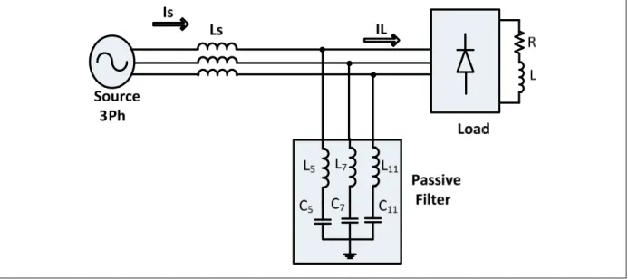
Hybrid series power filter (SHPF) systems have a series active filter with a passive filter connected to the network. An SHPF is shown in Figure 1.5. This type of power filter system not only improves power quality, but also decreases current harmonics. To that end, several different solutions have been put forth as options. Of these, series and shunt active power filters are well-positioned as alternative solutions to compensate for problems related to current and voltage power quality in distribution systems. A broad range of shunt APF and series APF topologies have been suggested by a number of researchers. However, series APF systems need to supply active power in order to preserve the requisite level of load voltage throughout voltage sag. Simultaneously, power flow in SeAPF systems can dramatically increase throughout voltage sag. In this case, the energy sources should be inserted into a series APF system (Javadi, 2016).
Figure 1.5 Hybrid series power filter configuration
A number of different solutions have been proposed to enhance power quality. These solutions succeed in resolving many issues related to power quality, such as load reactive power, voltage and current harmonics, and voltage swell and sag. The most promising of these solutions are detailed in the following sections.
1.5.2 Novel HSAF for Power Quality Compensation
Hamadi (2007) discussed a series hybrid active filter (SHAF) to compensate voltage/current harmonics, reactive power, load type, and resonance damping. Hamadi’s (2007) approach is essentially a collective system of series active filters and shunt passive filters as shown in Figure 1.6. Combining active and passive power filters succeeds in reducing ‘‘the power rating of the active section, while the novel SPF uses a minimal component count. The principal of the SPF is to have a high impedance at the standard frequency and a very low impedance for higher harmonics compensates created by the load’’ (Hamadi, 2007). The power factor is thus improved through the compensation of all reactive power and harmonics. Furthermore, the SAF offers high impedance levels via harmonics compensation, forcing the harmonics to flow over the ShPF and compensating both the reactive power and voltage harmonic. The synchronous reference frame (SFR) approach is used for controlling the SeAF in this application.
In this section, a configuration for a novel HSAPF for power quality compensation is discussed. This version contains both a SeAPF and ShPF, with a model voltage-type of source and current harmonics. Specifically, the SeAPF is useful for extending the fundamental frequencies of either very low or very high impedances that have been created due to the sensitivity of loads to variations "in the supply voltage. Because it can inject a voltage component in series with the supply voltage, it is considered a controlled voltage source" (Hamadi, 2007).
Hence, by controlling the SeAF, reactive power, the load harmonic voltages and the source voltage distortion can all be compensated. At the same time, there is a contribution to the ShPF. At fundamental frequencies, the ShPF contributes low levels of impedance as well as higher levels of resistance K for harmonic currents that are load-related. In this way, such currents must enter the ShPF. This means that because both the load/source harmonic voltages and the controlled compensation voltages are more or less the same with regard to amplitude, although they are not the same in phases: the one essentially cancels out the other.
The method that applies control as a means to create reference compensating voltages is crucial in the series APF. In generating the appropriate compensating voltages, the source harmonic component must be precisely detected in order to give correct series APF reference voltages. In fact, control algorithms which are utilized for obtaining SeAPF references are derived from parts of synchronous reference frames. In this approach, we can use an active power filter to play the role of both harmonic isolator and current-controlled voltage source, effectively preventing source harmonic voltages from entering loads or load harmonic currents from entering sources. In Figure 1.7, we can see how the control method is applied in series APF reference compensating voltages.
Figure 1.7 Control scheme of active power filter
1.5.3 New HSAF Configuration to Offset Reactive Power, Current/Voltage Harmonics, and Voltage Swell/Sag
Hamadi (2009) introduced a new model of series hybrid power filter (SHPF) configuration adaptable to all harmonic loads. The novel filter comprises a shunt passive filter and a small rated series active power filter (SAPF), with changing inductance that utilizes a thyristor control reactor (TCR). The DC voltage found at the load side of a model voltage harmonics source (e.g., a diode bridge rectifier followed by a capacitor) serves as a source of DC power for the SAPF. Hamadi (2009) used a MATLAB/Simulink simulation to develop the hybrid filter and then was successful in applying it for offsetting voltage sag, swell and harmonics, as well as the current harmonics and load reactive. The configuration is shown in Figure 1.8.
A
B
C
a b
c
Figure 1.8 Proposed series hybrid power filter configuration
Hamadi (2009) used non-linear-type control in his research. This approach controls the SeAF in order to offset reactive power, voltages related to load harmonics, and distortions in the source voltage. Furthermore, it is intended to support the passive filter that provides ultra-low impedance for higher than normal resistance in currents of load harmonics as well as for standard frequencies. As a result, the load harmonic currents can enter the ShPF. This method of control utilizes hybrid control and simultaneously detects the source current as (abc) and the load voltage VL (abc) in order to obtain harmonic parts as a means to boost the series transformer impedance levels for harmonic frequencies.
The offset effects are essentially related to the ration of control gain (k), which represents the rations for compensating harmonic voltages created as a result of the SAPF response to harmonic currents moving through it. As can be seen, by reducing k from 5 to 2, there is a subsequent decrease in the harmonics amplitute of the series transformer voltages, which then adversely impacts the filtering effect. When k = 5, the reflected impedance of SAPF is quite
high, enabling the load current harmonic to move through the shunt passive branches (Hamadi, 2009).
The main reason for wanting to control the TCR is to enable control of the thyristor’s firing in order to control the reactor current. This is done to gain control over TCR-absorbed reactive power. When applying the abc format, we can use the laws of voltages and currents proposed by Kirchhoff, but removing the inductance resistor used in the system. From this, we can obtain 3 differential equations.
1.5.4 SHAPF for Mitigating Voltage Unbalance and Harmonics under Unbalanced Non-Sinusoidal Supply Conditions
Mulla (2012) introduced a novel definition for instantaneous reactive, active and apparent power quantity. The work also discussed the decomposition of a voltage vector for different components of power quantities, as well as reference generation for a series hybrid active power filter (SHAPF) for supply voltage balancing and harmonic elimination as shown in Figure 1.9. Additionally, Mulla (2012) applied the proposed control scheme to SHAPF, recording the simulation results. Along with its primary aim of relieving current and voltage type harmonics, SHAPF helps to resolve problems related to power quality, including unbalance, swell and sag, and voltage (Mulla, 2012).
Figure 1.9 Circuit configuration of the SHAPF
Figure 1.10 shows the proposed novel algorithm of SHAPF for generating reference voltage, Mulla (2012) performed the tests under unbalanced non-sinusoidal supply conditions. He also decomposed multiphase vectors of voltages into quantities that represent various power components. Because instantaneous reactive and active power includes an oscillating component as well as an average component, it is possible, using vector algebra, to obtain the voltage vectors corresponding to average and oscillating powers. Moreover, because it is a series arrangement, non-sinusoidal and unbalanced fundamental components of source voltages can be added. This addition can be accomplished by appropriate modification of the reference for harmonic mitigation.
Figure 1.10 TCR control scheme for SHAPF
In this section, the researcher used 3-phase voltage generation as a reference (Mulla, 2012). The existing control strategies for SHAPF depend on decomposing the voltage vector by applying the generalised instantaneous power theory for SHAPF under the non-sinusoidal supply condition. The control scheme not only is valid for unbalanced and balanced, non-sinusoidal and non-sinusoidal source conditions, but is also able to balance load voltages and deal with voltage or current-type harmonics (Mulla, 2012).
1.5.5 Improving Power Quality Through a Photovoltaic-based 3-Phase 4-Wire SHAPF
In this study, Vijayakumar (2014) presented a photovoltaic panel (PV) and a battery connected to a series hybrid power filter (SHPF) comprised of an LC shunt passive filter and a series active power filter as shown in Figure 1.11. The primary benefit in using this system is its ability to compensate current harmonics, voltage harmonics and voltage interruption throughout an entire day. The SAPF requires an energy source in order to compensate the voltage swell and sag. At the same time, the topology of this system uses a green energy source linked to an energy storage unit to gauge the SAPF DC-link voltage needed. The control strategy here is grounded in the double formulation of the compensation system principles with adaptive fuzzy logic control (FLC). Vijayakumar (2014) also proposed a novel coordinate reason control that can offer ongoing harmonics and outage compensation under various conditions.
Figure 1.11 PV-based SeAF with ShAF topology
Vijayakumar (2014) studied the PV-interfaced 3P4W series hybrid active power filter as a means for offsetting voltage interruption/unbalance, voltage sag/swell, and harmonic currents. The intended users are either commercial (small industry) or residential. The researcher presented a PV system with battery attached to an SHPF comprised of an LC shunt passive filter and SAPF. The main benefit in using this approach is compensation gains for the voltage interruption, and current and voltage harmonics. The SAPF requires an energy source to compensate the voltage sag and swell, and the topology of this system also employs a low-energy approach that features an low-energy-storage unit for gauging the SAPF DC-link voltage demand.
Vijayakumar’s (2014) control strategy uses adaptive fuzzy logic (FLC) control instituted by doubling the principles of the compensation system. This method is then applied to control the voltage source inverter (VSI), as shown in Figure 1.12. A novel coordinate reason control is also introduced to provide constant outage and harmonics compensation under various conditions. Because the point of common coupling (PCC) must follow linear characteristics, the voltage and current of the 3P4W distribution system can be defined as vectors. Furthermore, the balance resistive load can be seen as an ideal reference load if the system currents are unbalanced and non-sinusoidal (Vijayakumar, 2014).
Figure 1.12 Proposed controller of PV-based SeAF
Any system, to be viable, has to offer its users a reliable and cost-effective sinusoidal balanced voltage. Hence, the compensation must be premised on a suitable reference load. This includes, for instance, a resistive load which is balanced and has linear features. As well, the supply voltage and source currents should be in-phase, as this would give the system a unity power factor (Vijayakumar, 2014).
The objective here is to obtain ideal behavior from the PCC though the load and equipment used for the compensation. The controller input signal current and voltage vectors are calculated from the source side and load, respectively. The voltage and current vectors would thus be multiplied to gain instant power, while load active power would be gained from a low pass filter (LPF). In the proposed control scheme, the purpose of the AFLC is to modify the PI controller parameters in order to decrease in-built error characteristics which might occur between the reference and system responses. Hence, the primary objective of this structure is to simplify the control scheme without resorting to mathematical modeling, but all the while maintaining optimal dynamic performance. In this approach, the fuzzy sets were defined for both the input and output variables.
1.5.6 Enhancing Power Quality Through the Use of Hybrid Series Active Power Compensator
Alireza (2016) introduced a novel THSeAF configuration with a sliding mode controller which was proposed and tested to overcome power quality issues of a voltage fed type of nonlinear load. In Figure 1.13 the theoretical modeling has been realized and simulated for further developments. A second-order SMC is developed and adapted for practical real-time implementations. A notch harmonic detection is implemented and tested to extract harmonic components of a polluted signal. It has been demonstrated that the proposed configuration along with the control approach is able to feature reactive power exchange with the utility as well. With regard to the control approach and taking advantage of the proposed robust structure, a harmonic-free voltage is delivered across the residential terminals (Javadi, 2016). The whole system is implemented on a real-time simulator to ensure feasibility of the developed controller. It is worthy to mention that this topology does not make use of a bulky transformer, which is mandatory for series active/hybrid filters topologies; it has a natural feature of limiting short-circuit current during faulty condition. It also replaces the function of UPS/UPQC devices with much less reactive and semiconductor components.
Figure 1.13 THSeAF connected to the single-phase system
The sliding mode control has been proposed in this case, the controller’s outer loop is composed of two parallel section based on a notch filter harmonics extraction technique. The first part is dedicated to compensate for load’s voltage regulation and added to a second part, which compensates for source current harmonics. The controller demonstrated in Figure 1.14 restores a stable voltage at the load PCC terminals, while compensating for reactive power and current harmonics. In the source current regulation block, the harmonics and reactive components remain behind after the fundamental (along with its phase degree) are extracted by the notch filter. Hence, the control gain, G, which indicates source impedance in the current harmonics, should be sufficient for ridding the grid of the current harmonics which entered via nonlinear loads. To obtain more exact compensation for the current harmonics, source/load voltage harmonics in the algorithm can also be taken into consideration. Both the source current and the source/load voltages serve as input signals for the system. To determine the
reference angular frequency, a single-phase discrete phase-locked loop (PLL) was employed, synchronized with the source utility voltage ( ). Furthermore, the has a core feature that is synched to the source voltage as a means to offset the reactive power. In this configuration, the gain, G, indicates harmonic convert resistance that is offsetting the currents at relative voltages, while indicates the generated reference voltage that is needed for removing source currents out of the harmonics (Javadi, 2016).
Figure 1.14 Control scheme of Hybrid Series Active Power Compensator
1.5.7 Enhanced Strategy to Offset Unbalanced Loads in HSAFs
As shown in Figure 1.15, Alireza (2015) presented an enhanced strategy for controlling HSAFs (hybrid series active power filters) featuring unbalanced nonlinear 3-phase 3-wire loadings. The researcher proposed an algorithm which used the instantaneous power theory as a means for removing harmonic components out of the supply current. The approach could also be applied in unbalanced loadings situations that have been contaminated by negative sequence components. A control strategy that relies on the sequence extraction algorithm was presented and tested by simulations, showing enhanced outcomes in harmonics reduction, particularly in unbalances and nonlinear loadings (Javadi, 2015).
Figure 1.15 Diagram for simulation
Figure 1.16 illustrates a control circuit with a 3-phase load current. As can be seen, the current has been changed to a stationary α–β frame, and the auxiliary positive/negative sequent voltages are created by the PLL circuit. Auxiliary voltages and currents from the α–β frame are then fed into sequence extraction blocks (positive/negative). From this, the α–β frame’s output sequence currents (positive/negative) are funneled into an inverse α–β transform, from which are obtained sequence currents (positive/negative) for the 3-phase abc frame. Next, following the extraction of the positive/negative sequence components, the harmonic currents are removed out of supply currents and the individual harmonic currents are funneled into a gain block (using K as the amplification factor) to determine reference voltage vF (Javadi, 2015). The vF is then used in every PWM convertor as a gate-control circuit.
Figure 1.16 Proposed control for series active filter
1.6 Research Objectives
The main objective of this research is to study, improve and test a low-cost 3-phase HSPF for dynamic reactive power and current harmonics compensation in a distribution power system. Furthermore, the 3-phase HSPF topology has been chosen for further investigation because it can provide the lowest initial size, weight, and cost. It could also possibly offer optimal dynamic reactive power compensation capabilities among competing topologies. Another reason is that its coupling LC serves as both a harmonic filter and switching ripple filter. Given the real and potential advantages of this topic, this thesis will therefore focus on HSPF topology in 3-phase distribution power system applications.
1.7 Conclusion
This chapter highlighted some basic characteristics and features of a hybrid series power filter while also providing an overview of harmonic compensation and power quality-related issues. As a technical background, research work centering on recent developments and applications of series hybrid power filter for improving their power quality was presented. As well, various
load types that compromise power quality were analyzed, while the effect of applying traditional passive components to harmonic compensation was looked into. The literature indicates that active filtering is the best approach for overcoming deficiencies in passive filtering, so the present work will pursue this research course.
Additionally, in this chapter, a short review of research dealing with active filtering in active compensation was provided. In order to decrease the costs associated with compensators while still enhancing power quality, issues such as voltage swell and sag, load reactive power, and current and voltage harmonics need to be addressed. The most optimized solution appears to be hybrid series filter configurations. Finally, after presenting a detailed overview of power definitions for multiple types of applications, this chapter discussed the importance of semi-conductor switching phenomena and practical modulation techniques for practical implementations.
CHAPTER 2
SLIDING MODE CONTROL WITH SERIES HYBRID POWER FILTER AND REDUCING SIZE WITH DIFFERENT PASSIVE FILTER DESIGN 2.1 Introduction
Following on the proposed system introduced in Chapter 1, this chapter discusses the viability of a series active compensator in a realistic distribution network. Recent research on harmonic pollution indicates that it not only has an impact on equipment in one plant but can also affect equipment in other plants. This alone is sufficient grounds for operators to limit or even restrict the possibility of disturbances by issuing standards for maximum allowable distortions. Two methods can be used to address power quality issues: load conditioning and installation of conditioning systems. Load conditioning ensures that equipment is relatively well protected from power disturbances and that operations can continue even under intense voltage distortion. The other solution to power quality issues installing line conditioning systems, serves as a means to counteract or mitigate power system disturbances (Rudnick, Dixon and Moran, 2003).
Recent developments in power conditioners and active power compensators are resulting in realizable solutions toward power quality improvement. One of the most promising solutions is the series active filter, which is generally less well-known and studied than the shunt configuration. This chapter presents a detailed overview of the series compensator, along with a discussion on its configurations, control strategies, and related involvements in the field. The chapter also looks into the series active hybrid compensator technology investigated by several researchers in their quest to overcome power quality issues. The studies include simulation results and evaluations of the passive components used to compensate for harmonics. Additionally, this chapter introduces a sliding mode control approach aimed at improving the accuracy of series harmonic compensation. A study gauging the system stability is also presented, together with experimental results.
2.2 System Configurations
Although series active compensators are not yet incorporated in power systems, they still have the greatest potential among active compensators for boosting the electric power quality of smart grids. The main problem preventing the application of series compensators are their complexity and high price tag, making them currently the least popular alternative for resolving power quality issues. Despite their inherent problems, series compensators could be repositioned in the future as the technology matures and simplifies.
Series compensators are generally divided into two categories: series active filters (SeAFs) and dynamic voltage restorers (DVRs). Both SeAFs and DVRs are highly complex and are joined to the grid through an isolation transformer. Although offering excellent isolation of the compensating system, the transformer is not only expensive, but brings with it a wide range of performance issues, including the need to be short-circuited if there is a fault in the secondary device, electrical losses, and hysteresis-related phenomena. In acknowledgement of these drawbacks, transformerless DVR technology has been proposed but is still in the development stage. Moreover, they are only able to compensate for voltage issues at the PCC, and as yet are unable to address current perturbations in the power grid.
2.2.1 Modeling of 3-Phase HSPF with Bridge Diode
With the goal of decreasing the power rating, the integration of active and passive power filters is crucial. Form Figure 2.1, the SHPF system utilizes a minimal component count, the principle of which is to provide low-impedance higher harmonics generated by the load and high impedance at fundamental frequency. This results in efficient compensation of reactive power and harmonics, thus enhancing and improving the power factor. As the SAF gives high impedance over harmonics compensation, it forces the harmonics to flow during the SPF and thus compensates the reactive power and voltage harmonics. The SAF is controlled via the synchronous reference frame (SFR) method (Hamadi, 2007). In the following section, the topology’s performance is evaluated and the simulation results discussed.
In order to gauge its performance level, the proposed SHPF configuration is simulated in a MATLAB-PSB environment. The efficiency of the proposed scheme is studied through
applying a set of loads consisting of current-source types of non-linear loads and voltage-source types of non-linear loads. Furthermore, in order to validate the SHPF performance, the system underwent testing for a variety of operating conditions, including steady-state, transience, voltage sag and swell, and balanced non-sinusoidal utility voltages. The control and results of this model are given in the following figures. They are also discussed in the following sections.
Figure 2.1 Series hybrid active filter with nonlinear load and linear load
2.2.2 Control Strategy of 3-Phase SHAF
A controlled series active filter functions to offset reactive power, source voltage distortion, and load harmonic voltages, and works together with shunt passive filters. These filters provide high resistance, K, against load harmonic currents as well as zero impedance when at fundamental frequencies. As a result, the load harmonic currents are funnelled towards the shunt passive filter. Because these voltages along with the load harmonic voltages (or occasionally source harmonic voltages) represent the same amplitude with opposing phases, each then cancels out the other as a means to enhance the shunt passive filter’s filtering capabilities while resolving any dynamic issues. Consequently, the series active filter can be