This is an author-deposited version published in: https://sam.ensam.eu Handle ID: .http://hdl.handle.net/10985/14717
To cite this version :
Taoufik QORIA, François GRUSON, Philippe DELARUE, Frédéric COLAS, Xavier GUILLAUD, Philippe LE MOIGNE - Modeling and Control of the Modular Multilevel Converter connected to an inductive DC source using Energetic Macroscopic Representation In: EPE, Lettonie, 201809 -n/a - 2018
Modeling and Control of the Modular Multilevel Converter connected to an
inductive DC source using Energetic Macroscopic Representation
T.QORIA, F.GRUSON, P.DELARUE, P.LE MOIGNE, F.COLAS, X.GUILLAUD
Univ. Lille, Arts et Metiers ParisTech, Centrale Lille, HEI, EA 2697-L2EP-Laboratoire d’Electrotechnique et d’Electronique de Puissance,
F-59000 Lille, France E-Mail: [email protected]
Acknowledgements
The results presented in this paper are part of ESPESA project that has received funding from the European Union’s Horizon 2020 research and innovation program under grant agreement No 692224.
Keywords
« Modular Multilevel Converter (MMC) », «DC side inductor», «High Voltage Direct Current (HVDC) », «Power transmission».
Abstract
The use of DC transmission is particularly advantageous for long-distance transmission and interconnection of asynchronous AC networks. Several converter topologies can be used for HVDC. Multilevel Modular Converters (MMCs) are the most favored given their technological advantages over other converters topologies. Due to their industrial maturity, they have become essential for all AC / DC conversion. So far, they have always been studied with a voltage source on DC side. However, when the converter is equipped with DC breaker, a series inductor is associated to limit current variations. This has consequences in term of modeling and control determination. This article aims to propose a modification of the control law in order to take into account this inductor. To facilitate the control organization, the Energetic Macroscopic Representation (EMR) is used.
Introduction
The debate over AC or DC electric power transmission systems dates back to the late 19th century with the dispute between Thomas Edinson's DC system and Westinghouse's AC technology. As a result, AC transmission systems became the predominant technology adopted. It was not until the 1930s, when the mercury arc valve was invented that the development of high voltage direct current (HVDC) transmission systems started [1]. In 1941, the first contract for a commercial HVDC system was placed and since then it became an alternative to AC transmission
HVDC technology is also the best solution to meet the demand for long-distance power transmission technologies thanks to their technical and economic advantages [2]. The first conversion technologies for HVDC applications were based on current source converters (CSCs) using thyristors. The introduction of power semiconductors with open/close capabilities has made possible the development of voltage source converters (VSCs). Recently, the modular multilevel converter (MMC) shown in Figure.1 has been quickly seen in a wide variety of applications as a result of significant advantages over previous technologies while retaining the properties of a conventional VSC.
With a sufficient number of levels, the output filter can be eliminated. In addition, since the switching frequency is lower for this converter, losses are reduced [3]. For the reasons stated, the MMC is a very interesting topology, not only for HVDC transmission, but also for other applications such as variable
speed drives, STATCOM, wind power generation. MMC technology has been widely accepted in the industry as it achieves high levels of power (1GW) and voltage (640kV).
Fig.1: Modular Multilevel Converter structure
In a point-to-point HVDC link, a DC fault results in the interruption of the link by opening the AC circuit breakers. In case of MTDC network, it is necessary to isolate the faulty link using DC breaker circuit which remains a major challenge until now. Thanks to the rapid progress of the technology, it is possible now to cut a direct current in a specific point of the network with the devices "Direct Current Circuit Breaker (DCCB) [4]". These latter are usually put in series with inductors of large values. It is possible, in this case, to represent the DC side of the converter by a voltage source in series with an inductor as shown in Figure 2. The purpose of this paper is not particularly concerned with faults, but it is focused on the impact of this inductor on the operation of the system and its consideration on the control law. It is also possible to generalize this study to an inductor coming from a DC transmission line [5].
Fig.2: Simplified diagram of the MMC connected to an inductive DC source.
𝑣
𝑔𝐿
𝑔, 𝑅
𝑔𝐿
𝑎, 𝑅
𝑎The conventional control strategies developed for an MMC connected to a DC voltage source [6-10] are no longer valid in the case of a strong inductor present on the DC bus, since this latter strongly influences the stability of the system as the shows the simulation below (Fig.3).
Fig.3: Conventional controls impact on the system stability
As it can be seen, the stability is no longer ensured in the case of a negative power flow. For this reason, it is important and necessary to have a suitable model of the MMC to integrate the impact of this inductor and subsequently to develop a suitable control law.
Most of the authors model the DC bus as a voltage source [6-10], the first work close to our problematic was done by [11] relying on several considerations and hypotheses at the modeling level. This latter considers that the DC power is equitably distributed in the three legs. This hypothesis is true in the case where the system is symmetrical with a perfect balanced network. But in case of a converter with many components (like the MMC), the symmetry of the system cannot be ensured (ex: losses in arms). Moreover, the balance of the network is not guaranteed [12].
The objective of this paper is to propose a new control law to keep the system stable for a high inductor value as the one considered in [4].
System modeling
Average model of the Modular Multilevel Converter
Given the large number of submodules (SMs), the study is based on the average model of the MMC considering that the capacitor voltages are well balanced [9]. Therefore, each arm is represented by an ideal DC / DC converter controlled by a modulation ratio defined as the ratio of the active submodule number divided by the total number of submodules, an equivalent capacitor of value 𝐶/𝑁 , and an equivalent voltage 𝑣𝑐𝑡𝑜𝑡 = 𝑣1+ 𝑣2+ 𝑣3… … + 𝑣𝑛.
The modulated voltage and current of each arm 𝑣𝑚, 𝑖𝑚 are respectively expressed as follow:
𝑣𝑚= 𝑚. 𝑣𝑐𝑡𝑜𝑡 (1)
𝑖𝑚 = 𝑚. 𝑣𝑚 (2)
We can therefore deduce the evolution of the modulated current by the following equation: 𝑖𝑚 = 𝐶𝑡𝑜𝑡.
𝑑
𝑑𝑡(𝑣𝑐𝑡𝑜𝑡) (3)
System equation
According to Kirchhoff's law, two equations are obtained from the inner loop of the MMC allowing a first modeling (𝑥 = 𝑎, 𝑏, 𝑐): 𝑉⃗⃗⃗⃗ 𝑑𝑐 2 − 𝐿𝑑𝑐 2 . 𝑑𝑖 𝑑𝑐 𝑑𝑡 − 𝑅𝑑𝑐 2 . 𝑖 𝑑𝑐− 𝑣 𝑚𝑢𝑥− 𝐿𝑎. 𝑑𝑖 𝑚𝑢𝑥 𝑑𝑡 − 𝑅𝑎. 𝑖 𝑚𝑢𝑥 = 𝑣 𝑔𝑥+ 𝐿. 𝑑𝑖 𝑔𝑥 𝑑𝑡 + 𝑅. 𝑖 𝑔𝑥− 𝑣 𝑛0 (4) −𝑉⃗⃗ 𝑑𝑐 2 + 𝐿𝑑𝑐 2 . 𝑑𝑖 𝑑𝑐 𝑑𝑡 + 𝑅𝑑𝑐 2 . 𝑖 𝑑𝑐+ 𝑣 𝑚𝑙𝑥+ 𝐿𝑎. 𝑑𝑖 𝑚𝑙𝑥 𝑑𝑡 + 𝑅𝑎. 𝑖 𝑚𝑙𝑥 = 𝑣 𝑔𝑥+ 𝐿. 𝑑𝑖 𝑔𝑥 𝑑𝑡 + 𝑅. 𝑖 𝑔𝑥− 𝑣 𝑛0 (5)
The modeling of the AC side is done by the summation of the equations (4) and (5): 𝑣𝑚𝑙𝑥− 𝑣𝑚𝑢𝑥+ 𝐿𝑎 𝑑 𝑑𝑡(𝑖𝑚𝑙𝑥− 𝑖𝑚𝑢𝑥) + 𝑅𝑎(𝑖𝑚𝑙𝑥− 𝑖𝑚𝑢𝑥) = 2(𝑣𝑔𝑥+ 𝐿𝑔 𝑑 𝑑𝑡(𝑖𝑔𝑥) + 𝑅𝑔 𝑑 𝑑𝑡(𝑖𝑔𝑥) (6)
Considering the variable change as in [13], with 𝑖𝑢𝑥 = 𝑖𝑔𝑥+ 𝑖𝑙𝑥 :
𝑣𝑣𝑥= 𝑣𝑚𝑙𝑥−𝑣𝑚𝑢𝑥 2 (7) 𝑣𝑑𝑖𝑓𝑓𝑥 = 𝑣𝑚𝑙𝑥+𝑣𝑚𝑢𝑥 2 (8) 𝑖𝑑𝑖𝑓𝑓𝑥 = 𝑖𝑙𝑥+𝑖𝑚𝑥 2 (9)
The fusion of equations (6) and (7) defines the equations vector of the state variables 𝑖𝑔𝑥 :
𝑣𝑣 𝑥− 𝑣𝑔𝑥 = ( 𝐿𝑎 2 + 𝐿𝑔) 𝑑 𝑑𝑡(𝑖𝑔𝑥) + ( 𝑅𝑎 2 + 𝑅𝑔) (𝑖𝑔𝑥) (10)
Conventionally, the line currents are controlled in Park domain.
In a similar way to the modeling of the AC side, the integration of (8) and (9) in the difference of the equations (4) and (5) allows the modeling of the DC bus:
𝑉𝑑𝑐 2 − 𝑣𝑑𝑖𝑓𝑓𝑥 = 𝐿𝑑𝑐 2 . 𝑑 𝑑𝑡(𝑖𝑑𝑐) + 𝑅𝑑𝑐 2 (𝑖𝑑𝑐)+ 𝐿𝑎. 𝑑 𝑑𝑡(𝑖𝑑𝑖𝑓𝑓𝑥) + 𝑅𝑎(𝑖𝑑𝑖𝑓𝑓𝑥) (11)
It is clear that the equation (11) contains coupled state variables since 𝑖𝑑𝑐 = 𝑖𝑑𝑖𝑓𝑓𝑎+ 𝑖𝑑𝑖𝑓𝑓𝑏 + 𝑖𝑑𝑖𝑓𝑓𝑐.
This coupling is due to the presence of the inductor on the DC side. As a result, the differential 𝑖𝑑𝑖𝑓𝑓𝑥 can no longer be controlled independently as in the case of an MMC connected to a DC voltage
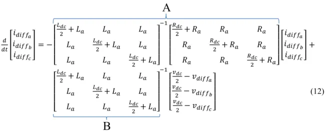
source. One solution consists in defining another model, compared to the one usually used for the MMC, by defining a new variable change allowing the decoupling of the system variables.
𝑑 𝑑𝑡[ 𝑖𝑑𝑖𝑓𝑓𝑎 𝑖𝑑𝑖𝑓𝑓𝑏 𝑖𝑑𝑖𝑓𝑓𝑐 ] = − [ 𝐿𝑑𝑐 2 + 𝐿𝑎 𝐿𝑎 𝐿𝑎 𝐿𝑎 𝐿𝑑𝑐 2 + 𝐿𝑎 𝐿𝑎 𝐿𝑎 𝐿𝑎 𝐿𝑑𝑐 2 + 𝐿𝑎] −1 [ 𝑅𝑑𝑐 2 + 𝑅𝑎 𝑅𝑎 𝑅𝑎 𝑅𝑎 𝑅𝑑𝑐 2 + 𝑅𝑎 𝑅𝑎 𝑅𝑎 𝑅𝑎 𝑅𝑑𝑐 2 + 𝑅𝑎] [ 𝑖𝑑𝑖𝑓𝑓𝑎 𝑖𝑑𝑖𝑓𝑓𝑏 𝑖𝑑𝑖𝑓𝑓𝑐 ] + [ 𝐿𝑑𝑐 2 + 𝐿𝑎 𝐿𝑎 𝐿𝑎 𝐿𝑎 𝐿𝑑𝑐 2 + 𝐿𝑎 𝐿𝑎 𝐿𝑎 𝐿𝑎 𝐿𝑑𝑐 2 + 𝐿𝑎] −1 [ 𝑣𝑑𝑐 2 − 𝑣𝑑𝑖𝑓𝑓𝑎 𝑣𝑑𝑐 2 − 𝑣𝑑𝑖𝑓𝑓𝑏 𝑣𝑑𝑐 2 − 𝑣𝑑𝑖𝑓𝑓𝑐] (12)
The matrix can be decomposed into left eigenvectors matrix denoted 𝑃, right eigenvectors matrix denoted 𝑃−1 and a diagonal matrix of eigenvalues D such as 𝐴 = 𝑃𝐷𝑃−1.
The multiplication of the equation (12) by the matrix 𝑃−1 on both sides allows to obtain the following
expression: 𝑃−1 𝑑 𝑑𝑡(𝑖𝑑𝑖𝑓𝑓𝑥) = 𝐷𝑃 −1𝑖 𝑑𝑖𝑓𝑓𝑥+ 𝑃 −1𝐵(𝑉𝑑𝑐 2 − 𝑣𝑑𝑖𝑓𝑓𝑥) (13)
From this equation, a new variable change is defined: 𝑖𝑑𝑖𝑓𝑓 𝑛𝑥 = 𝑃 −1𝑖 𝑑𝑖𝑓𝑓𝑥 (14) 𝑑 𝑑𝑡(𝑖𝑑𝑖𝑓𝑓𝑛𝑥 ) = 𝐷. 𝑖𝑑𝑖𝑓𝑓𝑛𝑥+ 𝑇( 𝑉𝑑𝑐 2 − 𝑣𝑑𝑖𝑓𝑓𝑥) (15) Where: 𝑇 = 𝑃−1𝐵, 𝑉 𝑑𝑐𝑛 = 𝑇𝑉𝑑𝑐 𝑣𝑑𝑖𝑓𝑓𝑛 = 𝑇𝑣𝑑𝑖𝑓𝑓.
Depending on this development, the combination of accumulation elements is now possible. Therefore the whole system is presented by 11 differential equations (11 state variables, 5 currents and 6 voltages). These equations are completely decoupled.
From the equations developed above, the MMC is presented using EMR tool [14] as shown in Fig.5:
Fig. 5. EMR of the Modular Multilevel Converter
System control
Inner loop controlThe 11 state variables are controlled from 6 control inputs 𝑚𝑢/𝑙 similarly for an MMC connected to a DC voltage source. The goal of the control is to obtain balanced sinusoidal currents on the AC side of amplitude such 𝑃𝑟𝑒𝑓, 𝑄𝑟𝑒𝑓 and a continuous current in steady state on DC side. These objectives are
m
u/lVdc
DC
i
dci
diffi
diffnv
diffi
diffnv
diffnv
mu/li
diffi
u/li
gi
gdqi
gdqv
vdq ACi
mu/lv
ctotA
B
achieved by controlling the new differential currents 𝑖𝑑𝑖𝑓𝑓𝑛 and line currents 𝑖𝑔𝑥. The controllers used
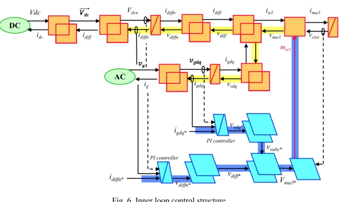
are the PI (Proportional Integral), it is also possible to use PR controllers (Proportional Resonant) [15]. The inner control law is deduced through a direct inversion of the model (Fig.6).
Fig. 6. Inner loop control structure
To avoid possible instability issues due to non-control of capacitor voltages 𝑣𝑐𝑡𝑜𝑡, an energy-based control strategy is developed in order to obtain a maximum control structure.
Energy based control
The energy based control strategy relies mainly on the power conservation law in each arm:
< 𝑃𝑢>=< 𝑣𝑚𝑢𝑥. 𝑖𝑢𝑥 >=< 𝑣𝑚𝑥. 𝑖𝑚𝑢𝑥 > (16) < 𝑃𝑙 >=< 𝑣𝑚𝑙𝑥. 𝑖𝑙𝑥 >=< 𝑣𝑙𝑥. 𝑖𝑚𝑙𝑥 > (17) Knowing that: < 𝑃 >=< 𝑑 𝑑𝑡𝑊 >= 𝐶𝑡𝑜𝑡 2 𝑑 𝑑𝑡(𝑣𝑐𝑡𝑜𝑡 2 )
The integration of the variable change (7) (8) and (9) in the equations (16) and (17) allows a first average energy modeling of arms:
< 𝑑 𝑑𝑡𝑊𝑢𝑥 >=< (𝑣𝑑𝑖𝑓𝑓𝑥− 𝑣𝑣𝑥) (𝑖𝑑𝑖𝑓𝑓𝑥+ 1 2 𝑖𝑔𝑥) > (18) < 𝑑 𝑑𝑡𝑊𝑙𝑥>=< (𝑣𝑑𝑖𝑓𝑓𝑥+ 𝑣𝑣𝑥) (𝑖𝑑𝑖𝑓𝑓𝑥 − 1 2 𝑖𝑔𝑥) > (19)
The sum "Σ" and the difference "Δ" of (18) and (19): 𝑑 𝑑𝑡𝑊𝑥 Σ=< 2𝑣 𝑑𝑖𝑓𝑓𝑥. 𝑖𝑑𝑖𝑓𝑓𝑥− 𝑣𝑣𝑥. 𝑖𝑔𝑥 > (20) 𝑑 𝑑𝑡𝑊𝑥 Δ=< 𝑣 𝑑𝑖𝑓𝑓𝑥. 𝑖𝑔𝑥− 2𝑣𝑣𝑥. 𝑖𝑑𝑖𝑓𝑓𝑥 > (21)
The differential current is defined as the sum of a DC component and an AC component:
𝑖𝑑𝑖𝑓𝑓𝑥 = 𝑖𝑑𝑖𝑓𝑓𝑥𝐴𝐶+ 𝑖𝑑𝑖𝑓𝑓𝑥𝐷𝐶 (22)
mu/l Vdc
DC
idc idiff idiffn vdiff
idiffn vdiffn vmu/l idiff iu/l ig igdq igdq vvdq AC imu/l vctot idiffn* vdiffn* vdiff* igdq* vvdq* vvabc* Vmu/l* PI controller PI controller Vdcn
We do the same for the new defined variables:
𝑖𝑑𝑖𝑓𝑓𝑥𝑛 = 𝑖𝑑𝑖𝑓𝑓𝑥𝑛𝐴𝐶+ 𝑖𝑑𝑖𝑓𝑓𝑥𝑛𝐷𝐶 (23)
Where < 𝑖𝑑𝑖𝑓𝑓
𝑥𝐴𝐶 >= 0 and < 𝑖𝑑𝑖𝑓𝑓𝑥𝑛𝐴𝐶 >= 0.
In steady state 𝑣𝑑𝑖𝑓𝑓𝑥 ≈𝑉𝑑𝑐
2 , and 𝑣𝑣≈ 𝑣𝑔. These considerations lead to two equations allowing the
control of the fictitious AC differential currents through the control of the energy difference 𝑊𝑥Δ
between upper and the lower arms, and the control of the fictitious DC differential currents through the control of the energy sum 𝑊𝑥Σ:
𝑑 𝑑𝑡𝑊𝑥 Σ =< 𝑉 𝑑𝑐. 𝑖𝑑𝑖𝑓𝑓𝑥𝑛𝐷𝐶. 𝑃 − 𝑣𝑔𝑥. 𝑖𝑔𝑥 > (24) 𝑑 𝑑𝑡𝑊𝑥 Δ=< −2𝑣 𝑔𝑥. 𝑖𝑔𝑥− 2𝑣𝑔𝑥. 𝑖𝑑𝑖𝑓𝑓𝑥𝑛𝐴𝐶. 𝑃 > (25)
Unlike conventional controls where the energy of the arms is controlled individually, the presence of a strong inductor in the DC side creates an energy coupling between the arms of the MMC.
It is remarkable from equation (24) that the total energy stored in each arm depends mainly on the power exchange between the power 𝑝𝑎𝑐, which depends on the direct component 𝑖𝑔𝑑, and the power 𝑝𝑑𝑐 which depends on the DC component of the differential current.
Only the average value of the AC power will be taken into account in the energy model, therefore, the fluctuating power is neglected. The compensation by the instantaneous AC power introduces an undesired AC component into the differential currents, even if it reduces the ripple across the equivalent capacitor voltages [9].
The reference of line currents is defined from the measurement of the grid voltage and the active/reactive power of reference.
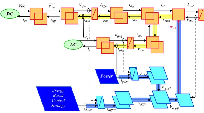
The control law of the energy based model (eq.24 and 25) is obtained by a direct model inversion:
Fig. 7. Maximal control structure of the Modular Multilevel Converter
Simulation and results
To validate the proposed control law, the simulations were performed on Matlab/Simulink.
The parameters used are indicated on Tab.1. These latter come from the HVDC INELF link [16], and the inductor value used on the DC side comes from the reference [4].
mu/l Vdc
DC
idc idiff idiffn vdiff
idiffn vdiffn vmu/l idiff iu/l ig igdq igdq vvdq AC imu/l vctot idiffn* vdiffn* vdiff* igdq* vvdq* vvabc* Vmu/l* Energy Based Control Strategy Power
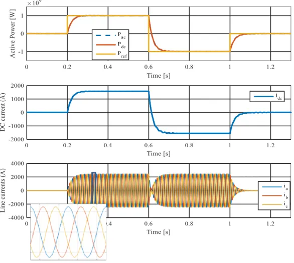
Only the variables at the input and at the output of the converter are presented in Fig. 8. At first, the power set point is initialized to zero until t = 0.2s, then P = 1GW is imposed until t = 0.6s, then -1GW until t = 1s.
Table I. System parameters
𝑃𝑛 1 𝐺𝑊 𝑅𝑎 50 𝑚𝐻 𝑉𝑟𝑒𝑠 192 𝑘𝑉 𝐿𝑎 50 𝑚𝐻 𝑓𝑟𝑒𝑠 50 𝐻𝑧 𝑅𝑑𝑐 300 𝑚Ω 𝑉𝑑𝑐 640 𝑘𝑉 𝐿𝑑𝑐 300 𝑚𝐻 𝑅 60 𝑚𝐻 𝐶𝑡𝑜𝑡 25 𝜇𝐹 𝐿 60 𝑚𝐻
It is remarkable that DC and AC powers follow the reference with a negligible difference due to Joule losses (the switches are supposed perfect). The line currents are sinusoidal and well balanced, and the DC side current side is continuous in steady state for each power set point. The system remains stable even with high 𝐿𝑑𝑐 value which was not the case for the control of the MMC connected to a voltage source (Fig.3).
Fig. 8. Input and output variables of the converter
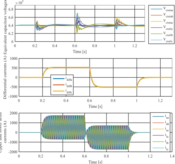
Figure 9 shows internal variables of the converter. It can be seen that the arms currents consist of a DC component and an AC component, the sum of the differential currents is equal to the DC current and the average values of the differential currents are almost equal, which means that the power is evenly distributed on the converter arms. The voltages across the capacitors are centered on their 640kV reference value.
The initial results of the simulation show that the system is stable since all state variables are well controlled.
Fig. 9. Internal variables of the converter
Conclusion
The first part of this paper allowed detailing the structure of the Modular Multilevel Converter, poses the issue related to the presence of an inductor in its DC bus, explains its operating principle, and its mathematical model. This part showed at first, the coupling of the system states due to the presence of the inductive node, thus, a methodology to solve this problem was proposed. The second part dealt with the converter control (line currents, the differential currents and the energy stored in the equivalent capacitors). Unlike other control strategies, all state variables have been controlled to avoid system instability. This ensures a good dynamic behavior and increases the system robustness.
Appendix
ENERGETIC MACROSCOPIC REPRESENTATION (EMR)[14] EMR is a systemic extension of COG, based on the interaction principle.
Action and reaction
variables
Energy source (system terminals)
Energy accumulation (energy storage indirect inversion (closed-loop control) Mono-physical converter (energy conversion) direct inversion (open-loop control) Strategy (energy management)
direct inversion using a disturbance rejection
References
[1] C.-K. Kim, V. K. Sood, G.-S. Jang, S.-J. Lim, and S.-J. Lee, Development of HVDC Technology, ch. 1, pp. 1–35. John Wiley Sons, Ltd, 2010.
[2] P. Rault, Dynamic Modeling and Control of Multi-terminal HVDC grids. PhD thesis, Ecole Centrale de Lille, Lille, France, 2014.T. Lubin, K. Berger, et A. Rezzoug, « Inductance and Force Calculation for Axisymmetric Coil Systems Including an Iron Core of Finite Length », Progress In Electromagnetics Research B, vol. 41, p. 377-396, juin 2012.
[3] B. R. Andersen, L. Xu, and K. T. G. Wong, “Topologies for VSC transmission,” in AC-DC Power Transmission, 2001. Seventh International Conference on (Conf. Publ. No.485), 2001, pp. 298–304. [4] K. Tahata el al., “HVDC circuit breakers for HVDC grid applications,” AC and DC power transmission,
11th IET International Conference on, BBrùingham,2015, pp19. doi: 10.1049/cp.2015.0018 [5] https://www.energy.siemens.com/hq/en/power-
transmission/hvdc/references.htm#ultranet-germany/projects
[6] F. Martinez-Rodrigo, S. de Pablo, and L. C. Herrero-de Lucas, “Current control of a modular multilevel converter for HVDC applications,” Renewable Energy, vol. 83, pp.318–331, Nov. 2015.
[7] J. Peralta, H. Saad, S. Dennetiere, J. Mahseredjian, and S. Nguefeu, “Detailed and averaged models for a 401-level MMC-HVDC system,” in 2013 IEEE Power and Energy Society General Meeting (PES), 2013, pp. 1–1.
[8] S. Rohner, J. Weber, and S. Bernet, “Continuous model of Modular Multilevel Converter with experimental verification,” in 2011 IEEE Energy Conversion Congress and Exposition (ECCE), 2011, pp. 4021–4028.
[9] P. Delarue, F. Gruson, and X. Guillaud, “Energetic macroscopic representation and inversion based control of a modular multilevel converter,” in 2013 15th European Conference on Power Electronics and Applications (EPE), 2013, pp. 1–10.
[10] U. N. Gnanarathna, A. M. Gole, and R. P. Jayasinghe, “Efficient Modeling of Modular Multilevel HVDC Converters (MMC) on Electromagnetic Transient Simulation Programs,” IEEE Transactions on Power Delivery, vol. 26, no. 1, pp. 316–324, Jan.2011.
[11] N. Cherix, M. Vasiladiotis, and A. Rufer, “Functional modeling and Energetic Macroscopic Representation of Modular Multilevel Converters,” in Power Electronics and Motion Control Conference (EPE/PEMC), 2012 15th International, 2012, pp.LS1a–1.3–1–LS1a–1.3–8.
[12] Rapport technique CEI 61000-4-11 « Techniques d’essai et de mesure – Essais d’immunité aux creux de tension, coupures brèves et variations de tension » 1994, Commission Électrotechnique Internationale. [13] H.Saad “MODÉLISATION ET SIMULATION D’UNE LIAISON HVDC DE TYPE VSC-MMC,” Ph.D.
Thesis, Ecole polytechnique de Montreal, Canada, 2015.
[14] A. Bouscayrol, B. Davat, B. de Fornel, B. François, J. P. Hautier, F. Meibody-Tabar, and M. Pietrzak-David, “Multimachine multiconverter system: application for electromechanical drives,” Eur. Phys. J., Appl. Phys., vol. 10, no. 2, pp. 131–147, May 2000.
[15] H. Cha, T. K. Vu and J. E. Kim, "Design and control of Proportional-Resonant controller based Photovoltaic power conditioning system," 2009 IEEE Energy Conversion Congress and Exposition, San Jose,CA,2009,pp.2198-2205.doi: 10.1109/ECCE.2009.5316374
[16] P. L. Francos, S. S. Verdugo, H. F. Álvarez, S. Guyomarch and J. Loncle, "INELFE — Europe's first integrated onshore HVDC interconnection," 2012 IEEE Power and Energy Society General
![Fig. 4. Average model of the MMC-arm [9]](https://thumb-eu.123doks.com/thumbv2/123doknet/7426755.219467/4.892.202.697.185.371/fig-average-model-mmc-arm.webp)