Science Arts & Métiers (SAM)
is an open access repository that collects the work of Arts et Métiers Institute of Technology researchers and makes it freely available over the web where possible.
This is an author-deposited version published in: https://sam.ensam.eu
Handle ID: .http://hdl.handle.net/10985/16995
To cite this version :
Unai ALONSO, Madalina CALAMAZ, Franck GIROT, Edurne IRIONDO - Influence of flute number and stepped bit geometry when drilling CFRP/Ti6Al4V stacks - Journal of Manufacturing Processes - Vol. 39, p.356-370 - 2019
Influence of flute number and stepped bit geometry when drilling
CFRP/Ti6Al4V stacks.
Abstract
Hybrid stacks made of carbon reinforced plastic (CFRP) and Ti-6Al-4V alloy (Ti) are often drilled together to reduce positional errors, enhance tight tolerances and minimize machining time. However, this is a complex task due to the dissimilar properties of each material. Tool geometry has a significant impact on the machinability of CFRP/Ti stacks. In this study, the influence of flute number and stepped bit design was experimentally investigated. Confocal and SEM microscopy were used to analyse the evolution of the cutting-edge micro-geometry and the dominant wear modes. The results have shown that a stepped design with three flutes leads to a slower wear progression, lower cutting forces and less hole damage. Furthermore, this paper also highlights the influence of the geometrical characteristics of the stepped tool design on the drilling stage number and on the shape of the thrust force signal. The information gathered can be used for the improvement of the process competitiveness in terms of the reduction of production time and cost.
Keywords: CFRP/Ti stacks; Drilling force; Wear modes; Quality inspection;
1. Introduction
In the aerospace industry, hybrid stacks of carbon reinforced plastic (CFRP) and Ti-6Al-4V titanium alloy (Ti) are being more widely used for structural applications due to their superior mechanical/physical properties. Such hybrid CFRP/Ti combination offers the advantages of both materials while minimizing their individual weaknesses. CFRP, for example, has high specific stiffness, good corrosion resistance and excellent fatigue strength. Titanium shows high strength to weight ratio, high fracture resistance and isotropic behaviour [1]. Moreover, the composite and metal alliance improves the impact strength and reparability problems of composites [2].
Due to these advantages, manufacturers such as Boeing or Airbus are employing CFRP/Ti stacks in new generation aircrafts to substitute single metal alloys (typically titanium or aluminium alloys). The potential applications for these hybrid materials include fuselages or wing connections, engine cowlings, fairings, door structures, wing panels etc. and its use is expected to grow in the next decade [3-5].The assembly of composite skins to metallic parts is preferably done using bolts and/or rivets. This process requires the machining of large number of holes where the control of the drilling operation becomes crucial.
CFRP and titanium plates are often drilled together using a one-shot strategy to improve productivity and reduce positional errors [5]. However, their dissimilar mechanical and thermal properties make it difficult to obtain the desired hole quality. The abrasive behaviour of the composite fibers and the low thermal conductivity of titanium are the main causes of the appearance of defects in both layers. When drilling the composite plate, fiber delamination is the matter of greatest concern since it affects surface finish and, more importantly, mechanical strength. Delamination can happen either at the entrance or at the exit of the CFRP layer due to two different mechanisms known as “peel-up” and
Unai Alonsoa, Madalina Calamazb, Franck Girot a,c, Edurne Iriondoa
aUniversity of the Basque Country, UPV/EHU, Faculty of Engineering of Bilbao, Department of
Mechanical Engineering, Alameda de Urquijo s/n, 48013 Bilbao, Bizkaia, Spain
b Arts et Metiers ParisTech, CNRS, I2M Bordeaux, Esplanade des Arts et Métiers, F-33405 Talence Cedex,
France
Ikerbasque, Basque Foundation for Science, Bilbao, Spain
“push-out” delamination. Generally push-out delamination is more extensive and thus, has to be considered more dangerous than peel-up delamination [5]. In CFRP-Ti stacks, push-out delamination can be reduced by starting the drilling process in the composite layer [6]. Other defects such as fiber pull-out, thermal matrix degradation or inter-ply delamination may also appear in CFRP. During the drilling of the titanium layer, high temperatures can result in large burrs and a poor diameter tolerance.
The appearance of such defects is greatly dependent on tool geometry, on the selected machining parameters and on wear evolution. Previous works have investigated the influence of some geometrical features of the tool when drilling CFRP-Ti stacks. Kumar et al. [7], for example, analyzed the effect of point angle on tool behavior and reported that flank wear increases faster in a tool with a point angle value of 118° as compared to one with an angle of 130°. Lazar and Xirouchakis [8] showed that a double point angle tip would result even in lower forces when drilling fiber-reinforced polymers (when compared to a single point angle drill). Kuo et al. [9] concluded that double-angle geometry improves ‘self-centering’ capability, reduces tool deflection and leads to better tolerances in drilling of Ti/CFRP/Al stacks.
Wilka et al. [10] compared the performance of four drills varying in flute number and helix angle. For drills with a helix angle of 20°, cutting torque in titanium was higher for a two-fluted drill as compared to a three-fluted one. When a helix angle of 40° was used, the opposite trend was observed. The reason of this cutting torque trend was not discussed in the paper. The influence of tool geometry on tool wear evolution was not evaluated either.
On the other hand, the use of stepped drills has been proved to be an effective solution for distributing mechanical loads in several cutting edges. With this optimized design, the hole is pre-drilled in the first stage and it is finished in the second one. Brinksmeier and Janssen [11] reported that the use of adapted step drills improves diameter tolerances, surface quality, and tool wear when drilling Al/CFRP/Ti and CFRP/Al stacks. Likewise, Shyha et al. [12] found that a stepped drill geometry reduces feed force when drilling CFRP due to a lower interaction between the major cutting edge and the workpiece. In a more recent work, Feito et al. [13] confirmed this result and pointed out that the improvements are more noticeable at lower feed rates. Nevertheless, there is still a lack of knowledge on the influence of tool geometry (step size, diameter ratio...) on the process forces. Besides, there are no studies that evaluate the influence of flute number in stepped drills when drilling CFRP/Ti stacks.
As aforementioned, excessive tool wear is one of the main causes of the appearance of damages in the workpiece. In this regard, Wang et al. [14] presented a comparative study based on the drilling of CFRP/Ti stack as well as its individual plates (CFRP-only and Ti-only). Edge rounding caused by the abrasiveness of the carbon fibers was regarded as the most relevant wear mode when drilling CFRP-only. For Ti-only tests, flank wear and edge chipping were the dominating tool wear modes. However, when both materials were machined together in the stacked configuration, tool wear was a combination of the edge rounding wear from drilling the top CFRP layer and the flank wear from drilling the bottom Ti layer. This result was also observed by Park et al. [15] for non-coated tungsten carbide drills.
Tool wear level is often quantified based on the measurement of the flank wear land. However, when a combination of flank wear and edge rounding occurs, local wear quantity (LWQ) has been proven
to be a more appropriate parameter for describing tool wear [10,16]. It is interesting to note that Wang [14] also observed that the LWQ value after drilling CFRP/Ti stacks was the sum of those obtained when drilling CFRP and Ti separately.
One of the strategies to reduce tool wear consists on changing the cutting conditions automatically according to the material being drilled. The identification of the drill position can be done by monitoring the thrust force (Fz) and by assigning lower and upper limits for each material. When drilling CFRP/Ti stacks, signal steps are significantly distinct and good results have been observed using this method [17]. However, the magnitude of Fz limits has to be adjusted as tool wear increases and, in order to do so, the variation of cutting forces with hole number should be studied. It is also important to note that the shape of the Fz signal is affected by the geometry of the drill. For non-stepped tools, Xu et. al [3] observed that five different zones in the Fz signals. Each zone was associated to a cutting stage of the drilling process. No works have been found on the influence of the stepped geometry in the cutting stage number and on the shape of Fz signal.
Considerable efforts have been devoted to understanding the cutting physics of CFRP/Ti and to improving drilling technology. However, there are still some key issues that should be addressed. This work aims to reveal the influence of a stepped drill design and its flute number on cutting forces and on tool wear. One of the main objectives is to describe the impact of the stepped geometry in the cutting stage number and in the shape of Fz signal. Moreover, the variation of the magnitude of cutting forces with hole number is evaluated for different tool designs. A special focus is also made on the study of the dominant wear modes and on the quantification of tool wear level by means of LWQ. Other fundamental process outputs such as the resulting hole diameter and the drilling-induced damages are also analysed.
2. Experimental procedures
2.1. Workpiece materialsThe composite plate used in the experiments was made of unidirectional ply of carbon fibers in an epoxy matrix with the following lay-up sequence [45/-45/90/0/90/0/45/-45/0/90/45/-45/45/-45/0]s.
The content of carbon fiber for each lamina was about 65% with an average ply thickness of 0.180 mm and a total thickness of 5.5 mm. This material is in accordance with the Airbus AIMS 05-27-002 specification and can be considered quasi-isotropic.
The titanium plate used in the experiments was Ti-6Al-4V (ASTM grade 5) alloy with a thickness of 5 mm and a hardness of 340 HV. The nominal chemical composition of the titanium and the fundamental mechanical/physical properties of both materials are shown in Table 1 and
Table 2 respectively.
Table 1. Chemical composition of Ti-6Al-4V (ASTM grade 5) alloy.
C H N O Fe V Al Ti
Table 2. Basic properties of the studied CFRP/ Ti-6Al-4V specimen.
CFRP Ti-6Al-4V
Tensile strength 1050 MPa Tensile strength 896 MPa
Young modulus 62 GPa Young modulus 114 GPa
Shear strength 75 MPa Poisson’s ratio 0.342
Glass transition temperature 167°C Compressive yield strength 860 MPa 2.2. Drill bit material and geometry.
Uncoated drills made of ISO K30 tungsten carbide (WC) were used in the investigation. Regarding the tool geometry, all the drills had the same helix angle (30°) and point angle at the first stage (130°). An overall view of the tools is shown in Fig. 1 and the main geometrical parameters of the drills used in the experiments are summarized in Table 3. One non-stepped (A) and two stepped (B and C) drill geometries have been investigated. A lower web thickness was measured on tool B; that could give less rigidity to the tool; nevertheless, smaller thrust forces are also expected.
Fig. 1 Front and side views of the used tools. Geometries of tool.
Table 3. Drill geometries
Tool geometry A B C
Flute number 2 2 3
Stepped/non-stepped Non-stepped Stepped Stepped
Diameter - first stage (mm) 5.86 5.06 5.06
Diameter - second stage (mm) - 5.85 5.87
Point angle - first stage (°) 130 130 130
Point angle - second stage (°) - 155 155
Helix angle (°) 30 30 30
2.3. Experimental setup for drilling tests.
The drilling trials were performed on a five-axis CNC machining center Hurco VMX 42 UHSi under dry conditions. CFRP/Ti-6Al-4V specimens were clamped by a fixture from the top side as shown in Fig. 2a. The stack sequence was CFRP on the top and Ti-6Al-4V on the bottom and was established with the industrial partner. As exposed by Ramulu et al. [18], this configuration generates less delamination in the composite material. During the tests, thrust force and cutting torque were registered using a Kistler 9170A rotating dynamometer (Fig. 2b). A multichannel charge amplifier (type 5238B from Kistler) connected to a Dewe43-A data acquisition instrument was used to convert the force signals into voltage signals. Afterwards, the software DewesoftX2 was employed to plot the recorded data. In this study, tool performance was analysed during the drilling of 65 holes or until the failure of the tool. In literature, the total number of holes drilled to carry out a tool wear study in CFRP/Ti-6Al-4V rarely exceeds 60 holes (even less when the drilling is done without any cutting fluid).
(a) (b)
Fig. 2 Experimental setup for drilling tests: (a) fixture configuration and (b) rotating dynamometer
2.4. Selection of cutting parameters.
Proper selection of machining parameters is essential to achieve high quality drilling results. In CFRP/Ti-6Al-4Vstacks, this is not an easy task since the ideal parameters for CFRP are not effective forTi-6Al-4V and vice versa. High feed rates (0.05-0.1 mm/rev) and low cutting speeds (10-30 m/min) result in an overall improvement of the hole quality in the titanium, but these conditions are damaging for the composite part since the high axial force increases delamination [18]. For CFRP machining, it is more advantageous to use lower feeds (0.01-0.05 mm/rev) together with higher cutting speeds (150-200 m/min) [19]. Since titanium causes the biggest problems, cutting conditions consisting of moderate feed speeds (around 0.05 mm/rev) and low cutting speeds can provide good results in both materials [1,20]. The machining conditions used in the experiments are summarized in Table 4. This parameter combination was chosen based on the results of a preliminary set of drilling tests and on the tool manufacturer recommendations. For each tool geometry, two drill bits have been tested.
Table 4. Cutting conditions
Tool geometry A B C
Cutting speed (Vc) 15 15 15
Spindle speed (N) 796 rpm 796 rpm 796 rpm
Feed per tooth(fz) 0.02 mm/rev 0.02 mm/rev 0.02 mm/rev
2.5. Tool wear evolution and hole quality analysis.
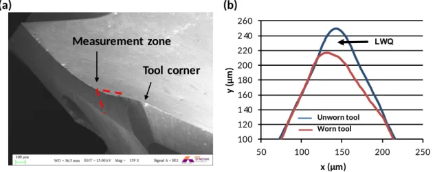
In order to investigate tool wear, the change of cutting tool edge micro-geometry at different stages of drilling was studied. Among the parameters proposed in literature, local wear quantity (LWQ) was chosen to characterize the cutting edge dullness due to the combination of flank and edge rounding wear. Its value is calculated by subtracting the area of the current profiles to the one of the unworn tool, as shown in Fig. 3b. At first, the 3D geometry of the main cutting edge was obtained by using a Keyence VHX-1000 confocal microscope and a depth composition function. Afterwards, a two dimensional profile was obtained at a distance of 600μm from the cutting edge corner and the LWQ value was calculated. Cutting edge profile measurements were taken before the tests when drills were new. Then, they were repeated after 5, 25, 45 and 65 holes to investigate tool wear evolution.
(a) (b) Tool corner Measurement zone 100 120 140 160 180 200 220 240 260 50 100 150 200 250 y (µ m ) x (µm) Unworn tool Worn tool LWQ
Fig. 3 (a) Tool edge geometry measurement zone. (b) Local wear quantity (LWQ) calculation.
In addition, a Zeiss Evo scanning electron microscope (SEM) was used to identify tool wear modes. High magnification pictures of the cutting edge near the margin and the chisel edge were obtained for all cutting tools. The cutting edge at the tool step was also analysed for geometries B and C. SEM pictures were taken when the drills were new and they were repeated after 5 holes and at the end of the tests.
Regarding hole quality assessment, hole diameter was measured at 2.5 mm from the hole entrance and at 2.5 mm from the exit, i.e. at the mid-thickness of the CFRP and the Ti-6Al-4V plates. A three point internal micrometer was used for these measurements (Mitutoyo, accuracy=0.001mm). Thermo-mechanical defects produced in the hole were also analyzed. In the composite plate, machining induced damage was evaluated by inspection with a Leica DMS1000 optical microscope. In the titanium part, burr height at the tool exit was measured using a Leica DCM 3D confocal microscope.
3. Results and discussion
3.1 Drilling process and force signal characterization
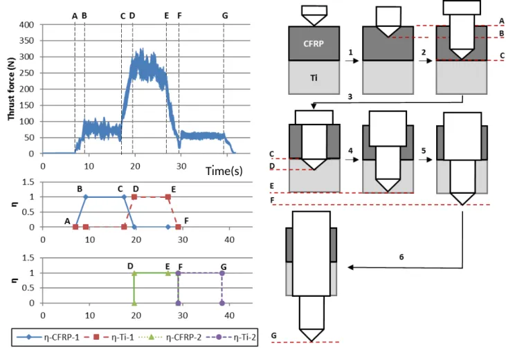
Cutting forces reflect the mechanical conditions in the chip generation and are an effective instrument to monitor the state of the tool. In hybrid CFRP/Ti stack drilling, the dissimilar properties of both materials and geometrical features of the drill make the cutting process go through a series
of transient and stationary stages. This sequence is reflected in the forces’ signals and has to be understood in order to correlate force data with the phenomena taking place in the cutting process. Fig. 4 shows the thrust force evolution over time for a non-stepped drill and a simplified scheme of the drilling operation. In a previous work, Xu et al. have comprehensively described the different stages of a stack drilling process with such tool geometry [3]. The authors simplify the cutting edge as a straight line and define a new parameter to describe the transient cutting stages. This variable is so-called “tool-workpiece interaction ratio” and is defined as follows:
(1) 𝜂𝑖=
𝐿𝑖
𝐿 𝜖 [0,1]
where Li corresponds to the portion of the cutting-edge in contact with a single material and L
indicates its total length. ηCFRP=0 and ηTi=0, for example, would denote the inexistence of tool-CFRP
interaction and tool-Ti interaction respectively; ηCFRP=1 and ηTi=1 would signify full tool-CFRP
interaction and full tool-Ti interaction respectively.
Fig. 4 Thrust force and tool-work interaction ratio (η) evolution over cutting time for a non-stepped drill.
Considering a one-shot operation, the entire CFRP/Ti stack drilling process can be divided into five stages:
Stage 1 (AB): the first phase starts when the cutting edge firstly touches the CFRP plate. ηC gradually increases until the total engagement of the cutting edge in composite. Thrust force also grows steadily from zero.
Stage 2 (BC): represents the period of full engagement of the tool tip in CFRP and can be considered as a steady drilling process. ηCFRP maintains equal to 1 and thrust force is kept
nearly constant.
Stage 3 (CD): this period starts when the tool firstly touches the titanium plate and finishes
when it is completely engaged in metal. During this stage, the zone involved in CFRP machining will decrease and the one removing titanium will grow. A continuous variation of ηCFRP and ηTi will occur and a significant increase of cutting forces will be noticeable.
Stage 4 (DE): denotes the period of full engagement of the tool tip and tool body in titanium and elasto-plastic deformation will be predominant. In this case, the parameter ηTi will keep
the constant value of 1.
Stage 5 (EF): indicates the period when the major cutting edge gradually exits the titanium
plate. The parameter ηTi will decrease and so will the thrust force until the completion of the
drilling operation.
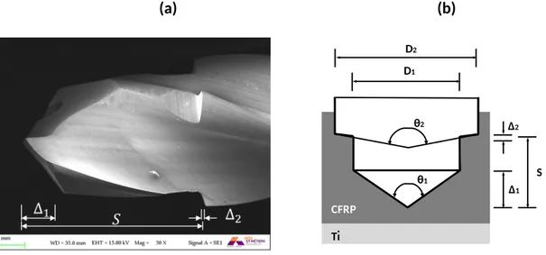
If the stack drilling is performed with a stepped drill bit, the whole machining process can be considered the result of two consecutive drilling operations with non-stepped tools. However, the resulting cutting stages will depend on the tool geometry and on the thickness of the CFRP and Ti plates. More specifically, the three axial distances denoted as Δ1, Δ2 and S in Fig. 5 will determine the cutting stage number. For example, when the distance between the tool tip and the second tool step (S) is smaller than the thickness of one plate, both drilling steps will be machining the same material in one stage of the process (see Fig.5b). Otherwise, this situation could not occur.
(a) (b) θ1 θ2 S Δ1 Δ2 D2 D1 CFRP Ti
Fig. 5 (a) Schematic representation of the drilling process with a stepped tool. (b) Geometrical parameters of the stepped drill used in the experiments.
If the cutting edges are simplified as straight lines, the axial distances associated to the cutting edges in the first and second steps (Δ1 and Δ2) can be roughly estimated through the following equations.
(2) 𝛥1= 𝐷1 2·tan
(
𝜃12)
(3) 𝛥2= 𝐷2‒ 𝐷1 2·tan(
𝜃22)
where D1 and D2 correspond to the diameters of the first and second cutting step respectively; θ1 and
geometries investigated in this work are shown in Table 5. Because of the small value of Δ2, the
cutting edge of the second cutting step will be considered perpendicular to the axis of the tool. This way, an easier interpretation of the drilling process and the evolution of the cutting forces can be made (see Fig. 6).
Table 5. Axial distance values for the investigated stepped drills.
Drill geometry B C
Δ1 1.18 mm 1.18 mm
Δ2 0.09 mm 0.09 mm
Step distance (S) 6.60 mm 6.60 mm
For the stepped drills, the evolution of thrust forces signal over time can be divided into six stages, as shown in Fig. 6. The corresponding simplified scheme for the drilling process can be seen on the right side of the figure.
Stage 1 (AB): the first phase starts when the tool tip touches the workpiece and continues
until the total engagement of the first cutting edge on composite. During this period, forces increase gradually as shown in Fig. 6(a). To illustrate the action of both drilling steps, the evolution of the tool-work interaction ratios are also depicted in Fig. 6. ηCFRP-1 and ηTi-1 would
correspond to the action of the first step of the tool and ηCFRP-2 and ηTi-2 to the second one.
Stage 2 (BC): is a period were the tool is fully engaged in CFRP machining and can be considered as a steady drilling process. ηCFRP-1 maintains its value and thrust force is also kept
approximately constant. As long as the thickness of each plate is smaller than S, cutting edges of both steps won’t be machining the same material simultaneously.
Stage 3 (CD): during this phase, the cutting edges of the first step are involved in the machining of the CFRP/Ti interface. The tool goes from complete composite machining to complete titanium machining. In consequence, ηCFRP-1 and ηTi-1 will vary progressively and an
increase of cutting forces will occur. For the particular drilling conditions investigated in this work, S ≈Δ1+LCFRP. Thus, it will be considered that the second step of cutting edges touches
the workpiece for the first time when the tool tip reaches the depth denoted as D.
Stage 4 (DE): in this period, both steps of the drill are fully engaged in the workpiece and
the cutting process can be considered as quasi-stationary. The cutting edges of the first step will machine titanium and the second one CFRP. Thus, ηCFRP-2 and ηTi-1 will keep the constant
maximum value of one. The highest cutting forces will take place during this stage.
Stage 5 (EF): represents a phase in which the first step of the drill gradually exits the titanium plate while the second step remains machining CFRP. Consequently, parameter ηTi-1 will decrease to zero whereas ηCFRP-2 will remain at one. At the end of this stage, the second
group of cutting edges will undergo a transition from CFRP to Ti which can cause an instability of the cutting process. This effect is reflected on the thrust force signal.
Stage 6 (FG): represents a steady drilling process in which the cutting edges of second step
are machining titanium. ηTi-2 maintains equal to 1 and thrust force is kept nearly constant. The
drilling process concludes with a progressive decrease of cutting forces to zero when both tool steps exit the workpiece.
Fig. 6 (a) Thrust force and tool-work interaction ratio evolution over time for a non-stepped drill.
3.2. Drilling force magnitudes
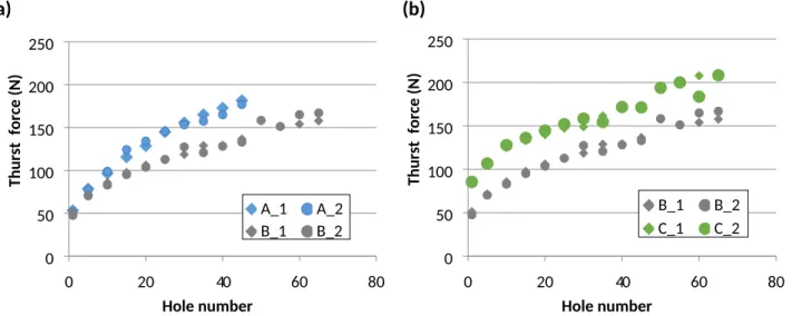
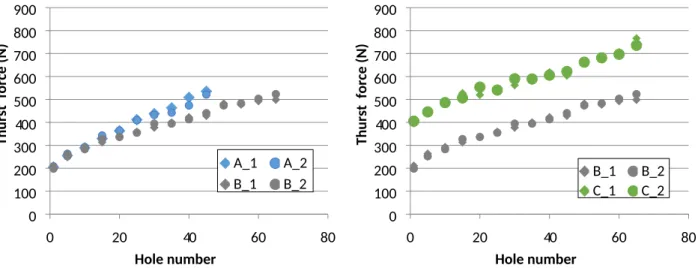
The effect of the stepped geometry and the flute number were analyzed based on the mean values of the steady drilling stages. That is to say, stages 2 and 4 for the non-stepped geometry and 2,4 and 6 for the stepped ones. In order to increase the statistic soundness of the results, two series of drilling tests were performed with each tool geometry. In Fig. 7 to 11 the two repetitions carried out with the non-stepped geometry (A) are named “A_1” and “A_2” respectively; the same nomenclature is used for the two other tool designs (B and C). For all the drill geometries, thrust and torque values experienced a faster increase during an initial period that lasted around five holes. Afterwards, a linear trend was noticeable with a less pronounced increase. This trend can be linked to the fact that tool wear is fast when the tools are new and it evolves more slowly after a few holes are made. Fig. 7 shows the thrust force evolution over the number of holes drilled in the CFRP plate. When the drills were new, forces for the three-fluted drills (C) were almost double compared to those with two flutes (geometries A and B). This effect could be produced by the bigger web thickness of geometry C. As the number of drilled holes increased, the thrust force raised due to tool wear. This tendency is in accordance with previous studies and can be explained by the progressive rounding of cutting edge and the increase in the tool-work material contact area in the thrust direction [4,15].
It can also be noted that forces in the non-stepped geometry (A) grow faster than in the stepped one (B) (a 50% more from hole 5 to 45). As shown in section 3.2, the non-stepped geometry experienced the strongest wear and lasted only 45 holes. On the contrary, the evolution of thrust force with the
hole number is very similar for the stepped tools with two and three cutting edges (Fig. 7b). Both tool geometries (B and C) showed an increase of approximately 100N from hole 5 to 65.
Fig. 8 depicts the evolution of thrust force when the major cutting edge is completely engaged in the titanium phase (stage 4). Surprisingly, thrust force history looks very similar to the trend observed when drilling CFRP (which is not the case when drilling Ti alone). These results are in accordance with those observed by Wang et al. [14] and are related to the fact that cutting edge rounding is the predominant wear mode in CFRP/Ti stack drilling. In the following sections, the wear influence in cutting forces will be further discussed.
The evolution of cutting torque in CFRP drilling is shown in Fig. 9. As stated before, torque values experienced a faster increase during the first five holes which was followed by a less pronounced linear trend. In order to compare the effect of different tool geometries, Fig. 9d shows the torque values for 5, 25, 45 and 65 holes. Higher torques were obtained with the non-stepped geometry (A) for the same amount of hole numbers due to the bigger tool diameter and faster wear. For the stepped geometries, the tools with three flutes (C) showed higher values compared to those with two flutes (B). The higher number of cutting edges and tool-workpiece contact surface in the margins could explain this result. A similar trend was also observed for the torques registered in the titanium plate (Fig. 10). Besides, Ti drilling yielded higher torque magnitudes than those gained in the CFRP drilling for all the investigated tool geometries. This effect can be attributed to the chip removal mechanism (elastic-plastic deformation) and to more severe friction conditions.
Fig. 11 illustrates the evolution of cutting forces in the drill bit step when machining the titanium plate (stage 6 of the drilling sequence). Linear growth with hole number was also noticeable after the first tests. However, the results exhibited poorer repeatability than those obtained when the major cutting edge was machining CFRP or Ti. For the data depicted in Fig. 7 and 8, the force values obtained in the two repetitions carried out with the same tool geometry always differed less than a 10%. Conversely, for the machining of Ti with the stepped tool (Fig. 11), a mean deviation of 30% was observed. The manufacturing difficulties regarding the cutting edge geometry in the tool step could explain this result.
(a) (b) 0 20 40 60 80 0 50 100 150 200 250 A_1 A_2 B_1 B_2 Hole number Thu rst f orce (N) 0 20 40 60 80 0 50 100 150 200 250 B_1 B_2 C_1 C_2 Hole number Thu rst f orce (N)
Fig. 7 Thrust force evolution in CFRP versus hole number. (a) Effect of the stepped geometry. (b) Effect of the flute number.
0 20 40 60 80 0 100 200 300 400 500 600 700 800 900 A_1 A_2 B_1 B_2 Hole number Thu rst f orce (N) 0 20 40 60 80 0 100 200 300 400 500 600 700 800 900 B_1 B_2 C_1 C_2 Hole number Thu rst f orce (N)
Fig. 8 Thrust force evolution in Ti or CFRP/Ti versus hole number. (a)Effect of the stepped geometry. (b) Effect of the flute number.
(a) (b) 0 20 40 60 80 0 0.05 0.1 0.15 0.2 0.25 0.3 A_1 A_2 Hole number Torqu e ( N·m) 0 20 40 60 80 0 0.05 0.1 0.15 0.2 0.25 0.3 B_1 B_2 Hole number Torqu e ( N·m) (c) (d) 0 20 40 60 80 0 0.05 0.1 0.15 0.2 0.25 0.3 C_1 C_2 Hole number Torqu e ( N·m) 5 25 45 65 0 0.05 0.1 0.15 0.2 0.25 0.3 A B C Hole number Torqu e ( N·m)
Fig. 9 Torque evolution in CFRP versus hole number (stage 2). (a) Non-stepped geometry. (b) Stepped geometry with two flutes
(a) (b) 0 10 20 30 40 50 0 0.2 0.4 0.6 0.8 1 1.2 1.4 1.6 1.8 2 A_1 A_2 Hole number Torqu e ( N·m) 0 20 40 60 80 0 0.2 0.4 0.6 0.8 1 1.2 1.4 1.6 1.8 2 B_1 B_2 Hole number Torqu e ( N·m) (c) (d) 0 20 40 60 80 0 0.2 0.4 0.6 0.8 1 1.2 1.4 1.6 1.8 2 C_1 C_2 Hole number Torqu e ( N·m) 5 25 45 65 0 0.5 1 1.5 2 Z2NS1 Z2S1 Z3S1 Hole number To rq ue (N ·m)
Fig. 10 Torque evolution in Ti CFRP/Ti versus hole number (stage 4). (a) Non-stepped geometry. (b) Stepped geometry with two
flutes. (c) Stepped geometry with three flutes. (d) Comparison of tool geometries.
0 20 40 60 80 0 50 100 150 200 250 B_1 B_2 C_1 C_2 Hole number Thrust force (N) 0 20 40 60 80 0 0.2 0.4 0.6 0.8 1 1.2 1.4 B_1 B_2 C_1 C_2 Hole number Torqu e ( N·m)
Fig. 11 Cutting forces in the second cutting step of the drill when machining the titanium plate (stage 6). (a) Thrust force. (b) Torque.
3.2. Tool wear
Fig. 12 shows the SEM images of the investigated drills at the unworn stage, after five holes and at the end of the tests. The pictures cover the major cutting edge, the margin and the rake face and higher magnification images are also shown for geometry B. Abrasive wear was noticeable at the major cutting edge and at the drill step. This wear mode is produced by two different phenomena. On the one hand, there is a grinding effect produce by free WC particles. During CFRP machining, the impact of the broken fibers produce mechanical stresses in the WC grains, which can lead to their fracture. [21]. These particles abrade the tool’s surface as they slide over the rake and clearance faces. On the other hand, carbon fibers can also scratch the Co binder making the WC grains more vulnerable to fall away partly or fully. [22]
Non-stepped drill with 2 flutes (A) Stepped drill with 2 flutes (B) Stepped drill with 3 flutes (C)
0 ho le s 5 ho le s A : 4 5 ho le s, B an d C: 6 5 ho le s Tool failure Adhesion Adhesion
Titanium adhesion was also observed on the major cutting edge, on the margin and on the rake face due to the stacking sequence of the drilling process (CFRP→Ti). Adhesion was more noticeable on the margin than in other parts of the tool. In this material, the higher temperatures result in hole shrinkage increasing friction between hole wall and the tool margin. This wear mode is a common defect when Ti is drilled alone, but it is less pronounced when CFRP and Ti are drilled together in a stacked configuration. In this case, the metal adhered to the tool in the previous hole is brushed away in the next operation. In fact, Wang et al. [14] observed that the titanium adhesion disappeared completely after penetrating only about 1mm into the CFRP plate. For the stepped drills, Ti adhesion was also noticeable on the rake face in the second stage of the tool (Fig. 13). The grinding process used to manufacture the drill geometry generates a rough surface, which enhances friction and titanium adhesion. Higher cutting speed and a higher temperature in this area could also contribute to increase adhesion.
Fig. 13 Adhesion at the rake face in the second drilling stage (C geometry).
Wear progress was also investigated by analysing the evolution of the cutting edge topology through the tests. It is important to note that the titanium adhered to the tool should be removed before measuring the micro-geometry. In order to do so, an additional hole was performed in the composite plate only. Wang et al. [14] proved that this is an effective way to clean the tool surface.
Fig. 14 shows the cutting edge profile evolution for each of the three studied geometries (A, B and C). As it can be seen, tool wear is a combination of both flank wear and edge rounding. However, wear progresses faster in the non-stepped tool (geometry A) than in the stepped ones (B and C). This result would explain the premature failure of that tool in the hole 45.
In order to analyse tool wear quantitatively, local wear quantity (LWQ) was calculated by subtracting the worn profiles to the fresh ones. As aforementioned, LWQ is a very suitable parameter to describe tool wear in such an edge rounding dominated case. Fig. 15a compares the LWQ progression for the non-stepped and stepped drills with two flutes (geometries A and B respectively). After the 45th hole,
the LWQ level generated in the non-stepped tool was approximately 50% higher than in the stepped one. This faster wear can be explained by the greater contact speed in the cutting edge corner between the tool and the carbon fibers. It is interesting to note that the CFRP plate contributes the most to the overall tool wear. In this regard, Wang et al. [14] compared tool wear in CFRP-only and CFRP-Ti drilling and observed that LWQ increased less than a 10% when drilling the stack.
The effect of tool wear is also reflected in cutting forces. Due to the different geometrical characteristics of the drills, this influence was analysed in terms of specific force magnitudes. In particular, drilling performance was compared during the second stage of the drilling process (full engagement of the tool tip in CFRP) based on specific thrust force (kf) and specific cutting force (kc).
𝑘𝑓= 𝐹𝑐𝑧 𝑧·𝑓𝑧·(𝐷/2) [𝑁/𝑚𝑚 2] 𝑘𝑐= 𝑀𝑑·8000 𝑧·𝑓𝑧·𝐷2 [𝑁/𝑚𝑚2]
where Fcz corresponds to the thrust force in [N], z to the cutting edge number, fz to the feed per tooth
in [mm] , D to the diameter in [mm] and Md to the cutting torque in [N·mm].
Fig. 16a compares the specific thrust force evolution for A and B geometries. An increase of approximately a 128% was observed for the non-stepped tool (A) from the 5th to the 45th hole while
for the stepped one it was smaller (91%). The faster wear progression in drill A would explain such difference. A similar conclusion can be drawn for stepped tools (see Fig. 15b and Fig. 16b). After 65 holes, the drill with two flutes (B) shows higher LWQ than the three fluted one (C) and results in bigger kfvalues.
Regarding specific cutting forces, higher values were obtained for the stepped drills with two cutting edges than for the non-stepped ones (see Fig. 17a). This result can be linked to the particular tool geometry used in the tests. As it can be seen in Fig. 1, all the drills were designed with a double margin configuration. During CFRP drilling, the drill only penetrates up to 5 mm and, under these circumstances, the geometry B has two active margins per cutting edge while A has only got one. The bigger contact surface would explain the difference in the specific cutting force. Nevertheless, the evolution of kc with hole number is consistent with wear level since it evolves more quickly in the
geometry A than in the B. Specifically, from the 5th to the 45th hole, an increase of 53% and 19% was
observed for A and B respectively. Likewise, if the stepped bits are compared (Fig. 17b), the geometry with a greater LWQ (B) also shows a faster growth of kc.
a) b) 5 25 45 0 500 1000 1500 2000 A B Hole number LWQ ( μm 2) 5 25 45 65 0 500 1000 1500 2000 B C Hole number LWQ ( μm 2)
Fig. 15 Local wear quantity (LWQ) evolution for the studied tools. (a) Comparison of the non-stepped and stepped geometry with two flutes. (b) Influence of the flute number on the stepped geometry.
a) b) 5 25 45 0 400 800 1200 1600 2000 A B Hole number kf (N/ m m2) 5 25 45 65 0 400 800 1200 1600 2000 B C Hole number kf (N/ m m2)
Fig. 16 Specific thrust force (kf) evolution for the studied tools. (a) Comparison of the non-stepped and stepped geometries with two
flutes. (b) Influence of the flute number on the stepped geometry.
a) b) 5 25 45 0 400 800 1200 1600 2000 A B Hole number kc (N/mm2) 5 25 45 65 0 400 800 1200 1600 2000 B C Hole number kc (N/mm2)
Fig. 17 Specific cutting force (kc) evolution for the studied tools. (a) Comparison of the non-stepped and stepped geometries with two
flutes. (b) Influence of the flute number on the stepped geometry.
3.3. Hole quality analysis
In CFRP/Ti stack drilling, hole quality has to be controlled in order to ensure a correct assembly. In the following subsections, a comparative study of the hole diameter and surface roughness is performed for the used drill geometries. Moreover, cutting-induced damages such as burr defect in titanium and delamination in the composite phase are also discussed.
3.3.1. Hole diameter
In CFRP-Ti drilling, the disparate thermal expansion coefficient and elastic properties of the stacked materials make it difficult to obtain a consistent hole size. Thus, hole diameter measurements were carried out on each individual layer as discussed in section 2.5.
Fig. 15 shows the evolution of the diameter with the hole number for each tool geometry and stacked phase. The displayed values correspond to the mean value of the repetitions carried out with the same drill geometry. As it can be seen, the diameters obtained in CFRP were higher than for Ti for all the tool geometries. This result is in accordance with the observations made by Xu et al. [3]. When a CFRP Ti cutting sequence is used, the hot and sharp metal chips abrade the previously drilled CFRP
hole during the evacuation process. As a consequence, the hole diameter in CFRP is enlarged. This effect can be avoided by using a Ti CFRP cutting sequence, but this strategy would promote higher
delamination at the exit of the composite plate. Moreover, the diameter on the CFRP phase increases steadily with the hole number for all the tested drills. This growth can be explained by the increase in cutting forces and instability of the drill bit.
a) b) 0 10 20 30 40 50 5.95 6 6.05 6.1 6.15 6.2 CFRP TI Hole number Diame te r (mm ) 0 20 40 60 80 5.95 6 6.05 6.1 6.15 6.2 CFRP TI Hole number Diame te r (mm ) c) 0 20 40 60 80 5.95 6 6.05 6.1 6.15 6.2 CFRP TI Hole number Diame te r (mm )
Fig. 18 Hole diameter evolution with hole number. (a) Non-stepped tool (“A” geometry), (b) stepped tool with two flutes (“B” geometry); (c) stepped tool with three flutes (“C” geometry).
If the different tool geometries are compared, it can be seen that the biggest diameter variation is produced for the non-stepped drill (A). In this case, the diameter increased 0.045 mm between the 5th and the 45th holes for the CFRP plate. In contrast, the tool with the same flute number and stepped
specific thrust forces would be the cause of such difference. This would also be the reason for the even smaller increase (0.005 mm) observed for the three-fluted with a stepped geometry (C). In this case, the wear level and the specific cutting forces are smaller as compared with geometry B. Moreover, for stepped tools (B and C) it was observed that the diameter increased linearly for both the CFRP and Ti phases among the holes 5 and 65. The slightly higher values obtained for the geometry C can be explained by the 0.020 mm bigger tool diameter in the unworn conditions. 3.3.2. Burr defect analysis
The burr defect produced in titanium is a crucial problem compared to other surface damages since it leads to disassembly, deburring and further re-assembly of the stacks. A burr can be created on both entrance and exit surfaces of the metallic plate, but the one produced at the tool exit is much larger and is often the main concern.
Burr formation is highly dependent on the tool geometry and can be thoroughly related to the frictional heat generation, tool engagement time and thrust force. In the following paragraphs, burr height measurements are compared. The influence of stepped geometry on the burr generation process is also discussed.
Fig. 15a shows the burr height evolution for the drills with two cutting edges (geometries A and B). The depicted data correspond to the mean value of the different repetitions for the same tool geometry and the error bars represent the maximum and minimum values. Over the course of 45 holes, the non-stepped tool (A) produced burrs that increase from 349μm to 768μm. This trend can be related to tool wear evolution and the increase on heat generation. As the cutting process progresses, frictional heat on the cutting edge elevates the temperature on the surrounding material. When the tool point reaches the bottom surface, the ductility of the Ti has increased; allowing the material to flow easier and making it more difficult for cutting off. The severe cutting edge rounding and flank wear also affect the proper shearing of the last thin layer of the Ti plate.
a) b) 1 5 25 45 65 0 500 1000 1500 2000 A B Hole number Bu rr height (μ m ) 1 5 25 45 65 0 500 1000 1500 2000 B C Hole number Bu rr height (μ m )
Fig. 19 Burr height evolution for the studied tools. (a) Comparison of the non-stepped and stepped geometry with two flutes. (b) Influence of the flute number on stepped geometries.
During the tests, burr type changed as hole number increased. It should be noted that drilling burrs produced in Ti are often classified into three types (uniform, transient and crown burr) according to the location of crack initiation [23]. A uniform burr formation was observed at the beginning of the test were fresh drills were used. Such burr type is produced when the formation process happens by means of a first fracture in the tool point followed by a secondary one at the periphery of the hole. Under such circumstances, a burr of small dimensions and a “round” cap are generated (Fig. 20a).
In the 41st hole, the burr formation mechanism changed to a crown type. In this case, the fracture is
initiated at the drill point and the burr is produced due to the plastic deformation of the remaining material in the hole perimeter (Fig. 20b). This variation in the burr formation mechanism, could explain the higher increase in burr height in the last 20 holes. A cross section of the 40th and 41st holes
(obtained by wire-EDM) is shown in Fig. 20c.
As shown in Fig.19a, the burr height values obtained with the stepped drill (B) were approximately double over the first 45 holes as compared to those observed for the non-stepped one (A). However, this difference cannot be associated to higher cutting temperature and material ductility at the end of the process, because the non-stepped drill suffers faster wear and depicts higher thrust forces.
a) b)
Fig. 20 Uniform and crown burr generation process in the non-stepped drill. (a) Schematic burr formation. (b) Cross section of holes 40 and 41.
The abnormally high values can be explained by the burr formation mechanism in the stepped tool, which is illustrated in Fig. 21. In this case, the final burr is the result of both drill bit steps. Firstly, a primary burr is generated as the tool point exits the titanium plate (Fig. 21a). This process is similar to the one taking place in a drilling operation with a non-stepped tool. As the tool step exits the workpiece, the cutting edges push out both the uncut material and the primary burr (Fig. 21c). This plastic deformation process could be compared to a redrawing operation in sheet metal forming and results in a comparatively large burr.
Fig. 19b compares the evolution of the burr height for the stepped tools (B and C). For the same number of drilled holes, higher burrs were observed for the two-fluted drill (B). This result could be explained by the faster tool wear and the higher thrust forces obtained with this tool geometry. It should be noted that the position at which bending starts is influenced by both the stiffness of the remaining material and by the thrust force. This effect would explain the observed differences.
(a) (b) (c) (d)
Fig. 21 Schematic illustration of the burr formation mechanism for stepped drills.
3.3.3. Delamination damage analysis
The damages occurring in the composite plate are the most critical ones. In most cases, they cannot be repaired and they are the source of crack initiation and fatigue fracture. Fig. 22 and Fig. 23 display the condition of the hole in the composite plate at the tool entry and tool exit zones respectively. Workpiece damage is more severe at the tool exit and can be related to the particular thermo-mechanical phenomena taking place at the interface zone.
When the tool starts drilling the metallic plate, the drill tip suffers vibrations due to the change in the material separation mode. Moreover, the metallic chips produced at the initial stage of Ti drilling scratch the bottom surface of the composite plate. These phenomena can be identified as the main causes of the observed mechanical damage. Besides, a color change in the composite was also noticeable. The temperature increase during Ti drilling would have induced thermal softening and degradation of the epoxy matrix.
Tool
geometry 5 holes 25 holes 45 holes 65 holes
A
B
C
Tool
geometry 5 holes 25 holes 45 holes 65 holes
A
B
C
Fig. 23 Hole condition in the composite plate at the tool exit.
In order to ensure the structural integrity of the machine part, it is important to quantify the magnitude of the mechanical damage at the CFRP/Ti interface. This would allow to stablish a hole number limit at which the tool should be replaced. To assess the damage extent, the one-dimensional delamination factor (Fd) was adopted for this work. This parameter is defined as the ratio of the
maximum diameter of the damaged area (Dmax) to the nominal hole diameter (Dnom). As can be seen
in the figures, the damage does not correspond to an isolated tearing of a fiber, but extends almost uniformly around the entire hole. In this study, digital analysis of the images was used to measure the value of the maximum diameter of the damaged area.
Fig. 24 reports the evolution of the delamination factor over the number of drilled holes. As can be observed, delamination factor increases with the number of holes. This evolution can be linked to the progressive tool wear and to the increase of thrust and cutting temperature. The rounding of the cutting edges would also entail a loss of cutting capacity and a poorer hole quality.
As shown in Fig. 23, mechanical damage and matrix discoloration were detected even after 5th hole
for the non-stepped tool (A). In this case, the delamination factor increased faster than for the stepped geometry (B). In fact, the diameter of the damaged zone was approximately 2 mm bigger after 45 holes. For the stepped geometries, the damage was minimal during the first holes and similar Fd values were obtained up to the 45th hole. A lower damage extent was noticeable after the 65th
hole for the drill with three flutes (C). These results are in agreement with the wear analysis. As stated before, the fastest wear was observed in the non-stepped tool (A) and, for the stepped geometries, C had a lower wear progression.
a) b) 5 25 45 65 1.00 1.10 1.20 1.30 1.40 1.50 1.60 A B Hole number De lam ina tio n fac tor (Fd) 5 25 45 65 1.00 1.10 1.20 1.30 1.40 1.50 B C Hole number De lam ina tio n fac tor (Fd)
Fig. 24 Delamination factor evolution for the studied drill geometries. (a) Comparison of the non-stepped and stepped geometry with two flutes. (b) Influence of the flute number on stepped geometries.
4. Conclusions
Tool geometry plays an important role when drilling CFRP-Ti6Al4V stacks. An experimental study has been performed to assess the influence of flute number and a stepped design. Based on the obtained results, the following conclusions can be drawn:
The analysis of cutting-edge profile evolution showed that a stepped geometry and a higher flute number leads to lower local wear quantity (LWQ) values and lower specific forces. Abrasion and adhesion were found to be the dominant wear modes. Abrasive wear was
noticeable at the major cutting edge and at the drill step. Titanium adhesion was mainly observed on the margins and on the rake faces located on the step.
The study also highlighted the influence of tool geometry on the drilling sequence and on the evolution of cutting forces over time. CFRP/Ti stack drilling with non-stepped tools always involves five cutting stages that differ on the characteristics of the interaction between the cutting edge and the workpiece. For stepped drills, however, the cutting stage number is not unique because it depends on the particular tool geometry and on the thickness of the composite and titanium plates.
In a stepped tool design, the distance between the tool tip and the step should be smaller than the thickness of each plate. This would avoid a cutting stage in which both the major cutting edge and the tool step are engaged in the same material simultaneously leading to lower cutting forces.
Regarding cutting forces, a linear evolution of the thrust force and the cutting torque was observed when the drill step was machining the Ti plate (stage 6 of the drilling process for a stepped tool design). This result would be linked to the progressive rounding of the cutting edges and to the increase in the tool-workpiece contact surface.
The diameter of the holes in CFRP and Ti increased linearly for the stepped tools. However, a smother increase was observed for the three-fluted drill due to the less significant wear progression.
Hole quality was found to be greatly affected by the tool geometry. Burr height values for the non-stepped drill were approximately double as compared to those observed for the stepped tool with two flutes. This result can be explained by the particular burr formation mechanism in the stepped geometry.
Thermo-mechanical damage at the exit of the CFRP plate was detected for the non-stepped tool after the 5th hole. For such geometry, the one dimensional delamination factor (Fd)
increased faster than for the stepped drills.
In general, the stepped drill with three flutes (C) yielded better performance in terms of various drilling responses (e.g. wear progression, force generation and hole damage) when used under identical cutting conditions. Future research works should consider the influence of the geometrical characteristics of the step.
Acknowledgements
The authors gratefully acknowledge the technical support received from Jérémie Bega (I2M Bordeaux, France) in the wear analysis of the drills and from Mikel Atxa (Kendu S.Coop). This work was performed within the framework of the Transborder Joint Laboratory LTC ÆNIGME between the University of the Basque Country, the University of Bordeaux and Arts et Métiers ParisTech.
References
[1] Xu J, Mkaddem A, El Mansori M. Recent advances in drilling hybrid FRP/Ti composite: A state-of-the-art review. Compos Struct 2016;135:316–38.
doi:10.1016/j.compstruct.2015.09.028.
[2] Kim D, Beal A, Kwon P. Effect of Tool Wear on Hole Quality in Drilling of Carbon Fiber Reinforced Plastic–Titanium Alloy Stacks Using Tungsten Carbide and Polycrystalline Diamond Tools. J Manuf Sci Eng 2015;138:31006. doi:10.1115/1.4031052.
[3] Xu J, El Mansori M. Experimental study on drilling mechanisms and strategies of hybrid CFRP/Ti stacks. Compos Struct 2016;157:461–82. doi:10.1016/j.compstruct.2016.07.025. [4] Pramanik A, Littlefair G. Developments in Machining of Stacked Materials Made of CFRP and
Titanium/Aluminum Alloys. Mach Sci Technol 2014;18:485–508. doi:10.1080/10910344.2014.955718.
[5] Kuo CL, Soo SL, Aspinwall DK, Carr C, Bradley S, M’Saoubi R, et al. Development of single step drilling technology for multilayer metallic-composite stacks using uncoated and PVD coated carbide tools. J Manuf Process 2018;31:286–300. doi:10.1016/j.jmapro.2017.11.026.
[6] Qi Z, Zhang K, Li Y, Liu S, Cheng H. Critical thrust force predicting modeling for delamination-free drilling of metal-FRP stacks. Compos Struct 2014;107: 604–9.
[7] Kumar MS, Prabukarthi A, Krishnaraj V. Study on tool wear and chip formation during drilling carbon fiber reinforced polymer (CFRP)/titanium alloy (Ti6Al4V) stacks. Procedia Eng
2013;64:582–92. doi:10.1016/j.proeng.2013.09.133.
[8] Lazar MB, Xirouchakis P. Mechanical load distribution along the main cutting edges in drilling. J Mater Process Technol 2013;213:245–60. doi:10.1016/j.jmatprotec.2012.09.020. [9] Kuo CL, Soo SL, Aspinwall DK, Bradley S, Thomas W, M’Saoubi R, et al. Tool wear and hole
quality when single-shot drilling of metallic-composite stacks with diamond-coated tools. Proc Inst Mech Eng Part B J Eng Manuf 2014;228:954405413517388.
doi:10.1177/0954405413517388.
[10] Wika KK, Sharman ARC, Goulbourne D, Ridgway K. Impact of number of flutes and helix angle on tool performance and hole quality in drilling composite/titanium stacks. SAE 2011 AeroTech Congr. Exhib., 2011. doi:10.4271/2011-01-2744.
[11] Brinksmeier E, Janssen R. Drilling of Multi-Layer Composite Materials consisting of Carbon Fiber Reinforced Plastics (CFRP), Titanium and Aluminum Alloys. CIRP Ann - Manuf Technol 2002;51:87–90. doi:10.1016/S0007-8506(07)61472-3.
[12] Shyha IS, Aspinwall DK, Soo SL, Bradley S. Drill geometry and operating effects when cutting small diameter holes in CFRP. Int J Mach Tools Manuf 2009; 49:1008–14.
doi:10.1016/j.ijmachtools.2009.05.009.
[13] Feito N, Díaz-Álvarez J, López-Puente J, Miguelez MH. Experimental and numerical analysis of step drill bit performance when drilling woven CFRPs. Compos Struct 2018;184:1147–55. doi:10.1016/j.compstruct.2017.10.061.
[14] Wang X, Kwon PY, Sturtevant C, Kim D, Lantrip J. Comparative tool wear study based on drilling experiments on CFRP/Ti stack and its individual layers. Wear 2014;317:265–76. doi:10.1016/j.wear.2014.05.007.
[15] Park KH, Beal A, Kim D, Kwon P, Lantrip J. Tool wear in drilling of composite/titanium stacks using carbide and polycrystalline diamond tools. Wear 2011;271:2826–35.
doi:10.1016/j.wear.2011.05.038.
[16] Montoya M, Calamaz M, Gehin D, Girot F. Evaluation of the performance of coated and uncoated carbide tools in drilling thick CFRP/aluminium alloy stacks. Int J Adv Manuf Technol 2013;68:2111–20. doi:10.1007/s00170-013-4817-0.
[17] Jallegas J, Cherif M, Jean-yves K, Cahuc O. Self-Adjusting Cutting Parameter Technique for Drilling Multi-Stacked Material Jeremy Jallageas. SAE Int 2015;2502:24–30.
[18] Ramulu M, Branson T, Kim D. A study on the drilling of composite and titanium stacks. Compos Struct 2001;54:67–77. doi:10.1016/S0263-8223(01)00071-X.
[19] Ahmad J. Machining of polymer composites. Boston, MA, US: Springer; 2009.
[20] Park KH, Beal A, (Dae-Wook) Kim D, Kwon P, Lantrip J. A Comparative Study of Carbide Tools in Drilling of CFRP and CFRP-Ti Stacks. J Manuf Sci Eng 2014;136:14501.
doi:10.1115/1.4025008.
[21] Masuda M, Kuroshima Y, Chujo Y. Failure of tungsten carbide–cobalt alloy tools in machining of carbon materials Wear 1993;169:135-140.
[22] Rawat S, Attia H. Wear mechanisms and tool life management of WC-Co drills during dry high speed drilling of woven carbon fibre composites. Wear 2009;267:1022–30.
doi:10.1016/j.wear.2009.01.031.
[23] Min S, Kim, J, Dornfeld, DA, Development of a drilling burr control chart for low alloy steel, AISI 4118. Journal of Materials Processing Technology 2001;113:4-9.