HAL Id: hal-01809349
https://hal.archives-ouvertes.fr/hal-01809349
Submitted on 6 Jun 2018
HAL is a multi-disciplinary open access
archive for the deposit and dissemination of
sci-entific research documents, whether they are
pub-lished or not. The documents may come from
teaching and research institutions in France or
abroad, or from public or private research centers.
L’archive ouverte pluridisciplinaire HAL, est
destinée au dépôt et à la diffusion de documents
scientifiques de niveau recherche, publiés ou non,
émanant des établissements d’enseignement et de
recherche français ou étrangers, des laboratoires
publics ou privés.
Analog slice turbo decoding
Matthieu Arzel, Cyril Lahuec, Fabrice Seguin, David Gnaedig, Michel Jezequel
To cite this version:
Matthieu Arzel, Cyril Lahuec, Fabrice Seguin, David Gnaedig, Michel Jezequel. Analog slice turbo
decoding. ISCAS 2005 : IEEE International Symposium on Circuits And Systems, Kobé, Japan, May
23-26, May 2005, Kobé, Japan. pp.332 - 335, �10.1109/ISCAS.2005.1464592�. �hal-01809349�
Analog slice turbo decoding
Matthieu ARZEL, Cyril LAHUEC, Fabrice SEGUIN, David GNAEDIG and Michel J ´
EZ ´
EQUEL
GET/ENST Bretagne/PRACOM, CNRS-TAMCIC
Technopˆole Brest Iroise, CS 83818 - 29238 BREST CEDEX 3 FRANCE.
Abstract— This paper presents the design of an analog turbo
decoder for the DVB-RCS standard. It uses a slice architecture which enhances the design in terms of simplicity, robustness, testability and reusability. Transistor-level simulations show po-tential throughput up to 1.2Gb/s for a 2.8mW power consumption per information bit and per state in a 0.25µm BiCMOS process.
I. INTRODUCTION
Research interest has grown over the last decade for analog decoding due to its potential advantages over digital decoding techniques in terms of speed, power consumption and on-chip area reduction [1]–[3]. Few proposed circuits are targeting industrial standards: [4] proposed a decoder for UMTS and in [5] the first steps toward a DVB-RCS decoder were presented. Recently, a particular type of turbo code was proposed in [7]: the slice turbo code. In slice turbo codes, frames are split into shorter ones. [7] showed that it does not introduce performance degradation. Implementing the decoder for this type of turbo code allows to concentrate on the design of a single elementary decoder much smaller than the one required to decode the full frame length. Thus, this design is simplier, more easily characterized, more robust and reusable for different frame lengthes. In this paper, a first analog implementation of slice turbo decoder is proposed for the DVB-RCS standard. The paper is organized as follow. Part II presents the slice turbo architecture. In part III the performances of the Maximum A Posteriori (MAP) decoder designed in [5] are reminded and the interleaving is descibed. Part IV presents some simulation results obtained form a behavioral model and transistor-level simulation of the slice turbo decoder.
II. SLICE TURBO ARCHITECTURE
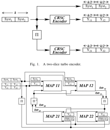
The principle of slice turbo codes is illustrated in Fig. 1. A frame of length k is sliced into m parts. Each sub-frame, or slice, is encoded independently using the usual turbo scheme of two circular recursive systematic convolutive (CRSC) encoders and an interleaver [6]. It is worth noting that the interleaving is done over the full-length k of the initial frame. The work presented in this paper deals with the shortest frame length of the DVB-RCS standard: 48 duo-binary symbols or 96 bits [7]. Therefore, each CRSC encoder in Fig. 1 encodes slices of 24 duo-binary symbols. The corresponding turbo decoder block diagram is illustrated in Fig. 2. It requires four elementary MAP decoders in the present case, two per slice to decode. Each decoder treats one slice in natural order (MAP 11 and MAP 12) or in interleaved order (MAP 21 and MAP 22) with the corresponding redundancy bits. The full
Π k/2 k/2 k/2 k/2 k/2 k/2 EncoderCRSC EncoderCRSC Syst1 Syst2 Syst1 Syst2 Y11 Y12 Y21 Y22 k
Fig. 1. A two-slice turbo encoder.
MAP 11 Π−1 MAP 12 Π Π MAP 21 MAP 22 Y12 Y21 Y22 Y11
Syst1 Syst2 Syst1
Y11 Syst2 Y12 Y21 Syst Π( )1 Y22 Syst Π( )2 Extr21 Extr22 Extr11 Extr12
Fig. 2. A two-slice turbo decoder.
received frame is fed at once to the decoder, thus there is no specific handling of data. This architecture is flexible since to accommodate for longer frame length, one simply has to increase the number of MAP decoders. Therefore, one only has to design a set of relatively small, robust and optimized MAP decoders to accommodate for any frame length of the standard. This greatly simplifies the design and the test of the overall decoder. More details are given in section III-A.
III. CIRCUIT DESIGN
A. Map design
The design of the MAP decoder was presented in [5] and only its main features are recalled here for convenience. The decoder is implemented using extended BJT-based Gilbert cells with analog I/O interfaces. Frames of 24 duo-binary symbols (96 bits treated by couples) altered by a gaussian noise are decoded. The simulated throughput is 600Mb/s for a power consumption of 1.4mW per information bit and
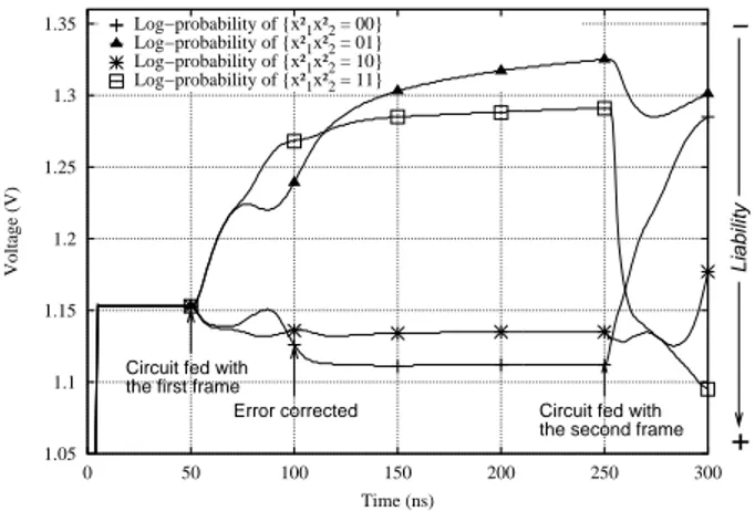
per state. Transistor level simulations were compared with behavioral ones: the designed decoder corrects the errors as expected (Fig. 3). This elementary MAP decoder is certified. Therefore it can be reused to decode longer frames in a slice scheme without testing each time the ability to correct errors.
1.05 1.1 1.15 1.2 1.25 1.3 1.35 0 50 100 150 200 250 300 Voltage (V) Time (ns)
Circuit fed with the first frame
Error corrected Circuit fed with the second frame
Liability − + Log−probability of {x²1x²2 = 00} Log−probability of {x²1x²2 = 01} Log−probability of {x²1x²2 = 10} Log−probability of {x²1x²2 = 11}
Fig. 3. Correction of an error (due to a gaussian noise at 2.4dB) in a transistor level simulation.
B. Interleaver design
A critical part in the slice architecture is the design of the interleaver [6].
IV. SIMULATION RESULTS
A. Transistor-level simulation
The full turbo decoder for two slices was simulated at the transistor level on the same frames used to test the MAP decoder. Fig.XX presents the correction of the same error treated by the MAP in Fig. 3. The presented output of one of the four MAP decoders benefits from the work of the others thanks to the exchange of extrinsic information through the interleaving network. The liability of the decision in the turbo case is better than in the MAP case. Indeed the difference between the most liable values and the others is greater in the turbo case than in the MAP one. The decoding speed can be estimated at XX, which is greater that the speed of a lonely MAP. The interleavers do not introduce latency but reduce decoding time in this case. Therefore the turbo scheme not only enhances error correction but speeds up decoding in an analog implementation. Graph of turbo Simulations enable
estimating the power consumption of the decoding core at 2.8mW per information bit and per state. The need for power doubles as expected: each information bit is decoded by two MAPs (one in natural order and one in interleaved order).
B. Behavioral modeling and simulation
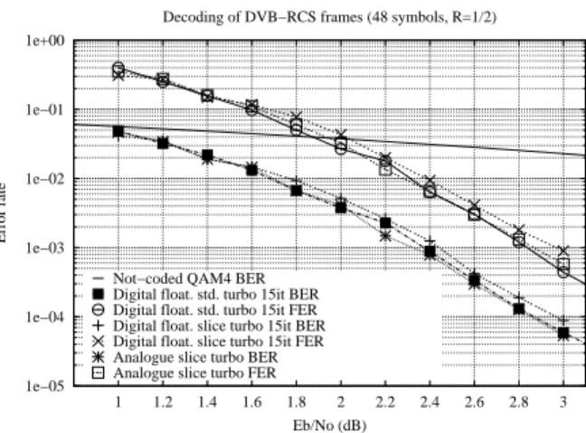
Behavioral modeling is necessary to evaluate the perfor-mances of the decoder in terms of Bit Error Rate (BER) and Frame Error Rate (FER) since to obtain these curves several thousands of frames need to be fed to the decoder. At transistor-level this is impractical due to long simulation time (over a week per frame!). Therefore, a behavioral model for the CRSC MAP decoder was developed in Simulink. Fig. 4 shows a behavioral simulation comparing the BER/FER performances of the analog slice turbo decoder and its digital counterparts: the DVB-RCS standard decoder and the pro-posed slice decoder. The digital decoders run for 15 iterations and uses floating point number representation to guaranty
1e−05 1e−04 1e−03 1e−02 1e−01 1e+00 1 1.2 1.4 1.6 1.8 2 2.2 2.4 2.6 2.8 3 Error rate Eb/No (dB)
Decoding of DVB−RCS frames (48 symbols, R=1/2)
Not−coded QAM4 BER Digital float. std. turbo 15it BER Digital float. std. turbo 15it FER Digital float. slice turbo 15it BER Digital float. slice turbo 15it FER Analogue slice turbo BER Analogue slice turbo FER
Fig. 4. Comparison of the correction performance of the DVB-RCS standard digital decoder, the slice digital decoder and the slice analogue decoder for frames of 48 duo-binary symbols.
the best MAP decoding performances. This figure actually shows that the analog turbo decoder performs better than its digital slice counterpart by 0.1dB and as well as the DVB-RCS standard digital decoder. The authors think that there are two possible explanations for this result. First, there is a real benefit in continuously exchanging information between the CRCS decoders instead of doing it iteratively: the analogue way is better for the slice implementation. Second, greater the size of the encoded frame, and also the asymptotic gain of the code, better the correction performance. Therefore the standard decoder without slices benefits from a greater asymptotic gain which enables this to achieve the performance of the analog slice decoder. To conclude, the slice analog decoder offers the same error correction performance as the standard one without slice but with the advantages of analog implementations: greater speed, lower consumption and reduced latency.
V. CONCLUSION
A suitable analog turbo decoder architecture to tackle long frames was presented. Behavioral and transistor-level simula-tions validate the concept. The circuit is expected to be sent to the foundry soon.
REFERENCES
[1] M. Moerz, T. Gabara, R. Yan, and J. Hagenauer, “An analog 0.25µm BiCMOS tailbiting MAP decoder,” in Proc. ISSCC, Feb. 2000, pp. 356– 357.
[2] F. Lustenberger, M. Helfenstein, H.-A. Loeliger, F. Tark ¨oy, and G. S. Moschytz, “An analog VLSI decoding technique for digital codes,” in Proc. 1999 IEEE Int. Symposium on Circuits and Systems, vol. 2, 1999, pp. 424–427.
[3] C. Winstead, J. Dai, S. Yu, C. Meyers, R. Harrison, and C. Schlegel, “CMOS analog MAP decoder for (8,4) hamming code,” IEEE J. Solid-State Circuits, vol. 39, no. 1, pp. 122–131, jan 2004.
[4] A. G. i Amat, G. Montorsi, S. Benedetto, D. Vogrig, A. Gerosa, and A. Neviani, “A full CMOS analog turbo decoder for UMTS coding schemes,” in 2nd
Analog Decoding Workshop Proceedings, Sept. 2003. [5] M. Arzel, C. Lahuec, M. J´ez´equel, and F. Seguin, “Analogue decoding
of duo-binary codes,” in Proc. ISITA 2004, Parma, Italy, October 2004. [6] D. Gnaedig, E. Boutillon, M. J´ez´equel, V. Gaudet, and P. Gulak, “On
multiple slice turbo codes,” in Proc. 3rd Int. Symp. on Turbo Codes and Related Topics, Brest, France, September 2003, pp. 343–346.
[7] Digital Video Broadcasting; Interaction channel for satellite distribution systems, ETSI.