Recent Advances in the Modeling of a Drillstring Inside a Curved Borehole
VINCENT DENOEL(a), EMMANUEL DETOURNAY (b)
(a) University of Li`ege, Belgium
(b) University of Minnesota, USA and CSIRO, Australia
1
Introduction
Accurate calculation of the position of the contacts between the drillstring and the borehole as well as the determination of the extent of these contacts is the true challenge of a torque-and-drag analysis. Such calculations are required to estimate the loss of torque from the rig to the bit under some assumed friction models, but also to assess the axial force on the bit (the “weight on bit”) given the known axial force at the rig (the “hook load”). Indeed, the weight on bit directly influences the rate of penetration, but also the drilling tendency of bottom-hole-assemblies equipped with rotary steerable systems [3, 6]. The accurate and efficient structural analysis of such a slender body, which is constrained to deform inside a borehole, is thus of paramount importance for the modeling of drilling operations.
In the late 1990’s, the state-of-the-art in torque-and-drag modeling has shifted from the “soft string model,” based on the assumption that the drillstring co-incides with the borehole axis [4], to advanced numerical methods with built-in management of the contacts. Standard finite element techniques have been ap-plied to the torque-and-drag problem, but they require a fine mesh to properly capture the response of the system in the vicinity of contacts [5]. Furthermore, the slenderness of the drillpipe, combined with the limited clearance between the drillstring and the borehole wall are two of the reasons that make the application of such standard techniques rather inefficient [2].
As an alternative, we have developed an approach that segments the drill-string between contacts and treats the series of unconstrained (or classical) elas-tica problems between successive contacts as a sequence of simpler auxiliary
is then performed in order to ensure consistency of the internal forces at the contacts. The kinematic non-penetration condition is imposed as an essential condition; conversely no spurious contact force is applied to the drillstring as long as it strictly remains between the walls of the borehole. Besides this formal treatment of contacts, the approach builds on a series of concepts that make the formulation well-conditioned and its implementation rather efficient. First, it is formulated within the Eulerian reference frame associated to the borehole, rather than the Lagrangian reference frame related to the drillstring, thus freeing the formulation of the integral constraints arising from the a priori unknown length of drillpipe between two contacts. Second, in order to determine efficiently the apparition of new contacts between the drillstring and the borehole, the posi-tion of the drillstring inside the curved borehole is parametrized by means of its transverse position relative to the borehole axis.
In its original version, the methodology was presented on the basis of an analytical description of the borehole geometry. Aiming at a wider application and as an intermediate step towards a 3-D model, we introduce in this paper a formulation based on a discrete description of the borehole, for a uniform drillstring and well (in diameter) and a planar trajectory. The main scope of this work aims at calculating successive equilibrium configurations of the drillstring inside a preexisting borehole. Although the context of a propagating borehole is not considered here, these calculations would be an integral part of a directional drilling analysis algorithm.
2
Borehole and Drillstring Description
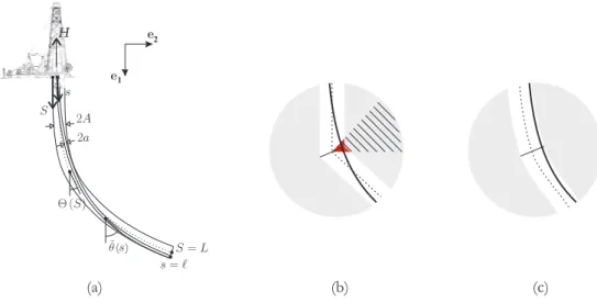
The geometry of the borehole axis can alternatively be described by Θ (S), the inclination of the axis as a function of the curvilinear coordinate S; or by (X (S) , Y (S)) the cartesian coordinates of the point parametrized by S, see Fig. 1-a. The two representations are related by
X0 = cos Θ; Y0 = sin Θ (1)
The walls of the borehole are further described by an offset A (S) on each side of this axis. The drillstring is parametrized by (X − ∆ sin Θ, Y + ∆ cos Θ), where ∆ (S)∈ [−A; A] represents the distance between the drillstring and the borehole axes.
In contrast to previous works [1], where only simple analytical forms of Θ(S) were assumed, we deal here with a conduit of arbitrary geometry. Namely, the
( )
H
1 2
(a) (b) (c)
Figure 1: (a) Borehole geometry - (b) Description of borehole with
piecewise-continuous inclination - (c) Description of borehole with piecewise-continuous inclination.
the inclination along the borehole at discrete coordinates Sk. It is necessary,
however, to define the geometry of the borehole between these points. Several families of interpolation are available: (i) a piecewise continuous interpolation
characterized by kinks at each Sk is not compatible with the signed-distance
model, as the existence and uniqueness of the solution is violated, see Fig. 1-b; (ii) a linear interpolation as illustrated in Fig. 1-c is possible; however (iii) a Hermite interpolation with continuity in the borehole inclination Θ and curvature
Θ0 at each Sk is preferable and is used in the following developments. The
main motivation for using the Hermite interpolation is that continuous contacts cannot spread beyond discontinuities in the curvature. This choice makes thus the number of continuous contacts insensitive to the discretization of the borehole geometry.
3
Segmentation Procedure and Auxiliary Problem
The algorithm presented in [1] is built on three nested loops. The outermost one is related to the determination of the actual contact pattern, i.e. the sequence of contacts including their number and their types. This loop segments the full problem into a series of auxiliary ones. In the middle loop, the exact location of the discrete contact(s) and the extent of continuous contact(s) -in other words, the bounds of each segment associated to an auxiliary problem- are determined by means of an appropriate nonlinear solver, while the auxiliary problems are
Consideration of an arbitrary conduit does not prevent the application of the same algorithm, although changes have to be implemented to make it more general. In particular, the solver related to the outermost loop has to act auto-matically as a decision algorithm. The change from a contact type to another, the apparition or disappearing of contacts, the split of continuous contacts, and other events have to be properly managed.
Besides, because the description of the borehole inclination is rather general (there could even be several intervals defining the borehole for a single auxiliary problem), an appropriate numerical solver has to be implemented. Instead of the shooting method used in the original contribution [2], a Bubnov-Galerkin method has been implemented here. It is particularly efficient in solving the fourth order nonlinear differential equation in ∆ (S) corresponding to the auxiliary problem.
4
Illustration
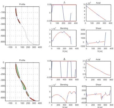
As an illustration of the capability of the algorithm, we consider the insertion of a slender drillpipe into a borehole, with a nominal clearance of 0.05 m. Snapshots of the continuous contacts as well as the pressure against the walls are represented in Fig. 2 for two different inserted lengths of drillpipe (L = 316 m and L = 776 m). The profile of ∆ (S) illustrates how the contact between the drillstring and borehole alternates from one side to the other, as a result of the macro-tortuosity of the borehole.
A vertical hook load, equal to the total weight of pipes inserted into the borehole, is applied. For short lengths of inserted pipe, the axial force is linearly decreasing from the total weight to zero. For longer lengths, the axial force profile curls, as a fraction of the total weight is balanced by the reaction forces along the contacts. The bending moment reflects the wall curvature in the contact zones; this is represented by the red solid lines in the bending moment diagram. Between these continuous contacts, the bending moment corresponds to that of a free elastica (a mix between a cable and a beam) with imposed end inclinations. The shear profile exhibits jumps corresponding to the discrete reactions that are known to take place at the ends of continuous contacts.
An interesting outcome of such an analysis is naturally the position and extents of the contacts along the drillpipe. They are represented in Fig. 3 as a function of the length of inserted drillpipe. In particular, Fig. 3 reveals the existence of two contact zones for an inserted length L = 316, and four contact zones for L = 776 m (these two cases are tagged with dotted lines). This form of representation of the contacts further shows that the extending and sliding contacts zones (resulting from the increase of axial force) mark the boundaries
0 200 400 600 800 -0.05 0 0.05 ! 0 200 400 600 800 -5 0 5 10x 10 4 Bending 0 200 400 600 800 -4000 -2000 0 2000 4000 Shear 0 200 400 600 800 0 0.5 1 1.5 2 2.5x 10 5 Axial -100 0 100 200 300 400 -600 -500 -400 -300 -200 -100 0 -100 0 100 200 300 400 -600 -500 -400 -300 -200 -100 0 0 100 200 300 400 -0.05 0 0.05 0 100 200 300 400 -1 0 1 2 3x 10 4 Bending Profile 0 100 200 300 400 -1000 0 1000 2000 3000 Shear 0 100 200 300 400 0 2 4 6 8 10x 10 4 Axial ! ! S [m] S [m] S [m] S [m] Profile
Figure 2: Insertion of a drillpipe into a borehole at two stages (inserted length L = 316 m and L = 776 m). Variation of the distance ∆ between the borehole and drillstring axis, axial force, shear force, and bending moment with curvilinear coordinate S 0 100 200 300 400 500 600 700 800 0 200 400 600 800 Inserted Length [m] Contact Position [m]
domains remains roughly identical throughout the whole contact pattern map. It depends actually on the clearance in the hole and on the weight of the drillpipe.
5
Conclusions
The approach to solve constrained elastica problems originally proposed by [1] has been extended to model a drillstring inside a borehole, which is here described by a curve characterized by a piecewise continuous curvature. Furthermore, an advanced numerical technique for the solution of the auxiliary problem has been implemented. This technique provides robust results, even when the domain of the auxiliary problem spans several segments defining the borehole.
References
[1] Deno¨el V., Detournay E. (2011). Eulerian formulation of constrained elastica.
International Journal of Solids and Structures 48(3-4): 625-636.
[2] Deno¨el V., Detournay E. (2009). The Problem of a Drillstring Inside a Curved
Borehole: a Perturbed Eulerian Approach. First International Colloquium on
Non-Linear Dynamics of Deep Drilling Systems, Li`ege, Belgium, 89-95.
[3] Downton G.C., M. Ignova. (2011) Stability and response of closed loop directional drilling system using linear delay differential equations. Joint IEEE/SPE Society Invited Session on Drilling Systems Automation and Con-trol, IEEE Multi-Conference on Systems and Control September 28-30, Den-ver, Colorado.
[4] Johancsik C., D. Friesen, Friesen, D. B., and Dawson, R. (1984). Torque and Drag in Directional Wells–Prediction and Measurement. Journal of Petroleum Technology 36(6): 987-992.
[5] Menand S., Sellami H., Tijani M., Akowanou J., Simon, C.. (2009) Buckling of Tubulars in Simulated Field Conditions, SPE Drilling & Completion, vol. 24, pp. 276-285.
[6] Perneder L., Detournay E. (2011) Steady-state solutions of a propagating borehole: Helical trajectory. Joint IEEE/SPE Society Invited Session on Drilling Systems Automation and Control, IEEE Multi-Conference on Sys-tems and Control September 28-30, Denver, Colorado.