A COMPARISON OF PISTON, SCREW AND SCROLL EXPANDERS FOR
SMALL-SCALE RANKINE CYCLE SYSTEMS
V. Lemort
a,*, L. Guillaume
a, A. Legros
a, S. Declaye
a, S. Quoilin
aa
Thermodynamics Laboratory, University of Liège, Campus du Sart Tilman, B49,
4000, Liège, Belgium
*corresponding author:
vincent.lemort@ulg.ac.be
ABSTRACT
This paper aims at helping the designer of micro-scale Rankine Cycle heat engines to best select the expander among piston, screw and scroll machines.
The first part of the paper presents a state of the art of these three technologies of positive displacement machines. The technical constraints inherent to each machine (rotational speed, pressure ratios, maximum temperatures, volumetric expansion ratios, etc.) are listed and the performance mentioned in the open technical and scientific literature is presented. The second part of the paper deals with the modeling of such expanders. Different simulation models are proposed: black-box, grey-box and white-box models. These three categories of modeling are specifically adapted to different purposes: design of the expander, design of the micro-CHP system, and dynamic simulation/control of the CHP unit.
The last part of the paper presents a graphical methodology of selection of expansion machines and working fluids based on operating maps. It is stressed that the selections of both the expansion machine and working fluid should be conducted simultaneously.
Keywords: Rankine cycle, piston, screw, screw,
expander
INTRODUCTION
Micro-, small- and medium-scale Rankine cycle systems are particularly suitable for distributed power production. Moreover, as external combustion engines operating with either water or lower boiling temperature organic fluids, they allow for the valorization of a wide range of heat sources at different temperature levels, such as biomass, solar and geothermal energy or waste heat. Among the promising applications of the Rankine cycle heat engines are the micro-CHP systems.
In such micro-scale systems, displacement expanders are generally preferred to turbines, because of their lower rotational speeds, their
ability to operate under large pressure ratios and their good performance.
For given operating conditions (and a working fluid), the selection of the expander depends on several criteria, such as its technical limitations (speed, supply temperature, etc.), its performance, its reliability (and indirectly its technical maturity), and its compactness. In this paper, focus is paid to three promising technologies of expanders for small-scale systems: piston, screw and scroll machines. The paper tries to address the following questions that often arise when designing a small-scale Rankine cycle system: what are the technical constraints of the expander technologies?, what kind of simulation tool should be used?, and could an optimal combination of working fluid and expander for a given micro-generation application be easily identified?
STATE OF THE ART
A short historyThe piston expander has been the object of many developments during the Industrial Revolution and up to the beginning of the 20th century. There has been a regain of interest in the 1970s, with the short development of car steam engines [1]. In the 2000’s, R&D work has been carried out on piston expanders for the replacement of the expansion valve in refrigeration cycles [2]. Piston expanders are currently used for niche-market applications: small-scale CHP and waste heat recovery on internal combustion engines (for instance [3], [4]). Axial piston expanders are usually preferred because of their compactness and their low level of vibrations (note that wobble-plate compressors are popular in mobile air conditioning systems).
Screw machines were initially developed by Lysholm during the period 1930-1942. In the 1950’s, they were extensively commercialized as gas compressors. In 1955, the invention of flooding allowed for cheaper machines without gears and screw compressors became popular
for refrigeration [5]. In the 1970’s, the development of machining tools allowed for reasonable compressor performance and since then many patents regarding the screw profiles have been issued [5]. The first records of expanders dated from the same period with their use as steam expanders in geothermal power plants [6].
The scroll machine has been patented in 1905 by Creux as an engine. However, the first industrial applications of scroll machines dated from the 1980’s, with the introduction into the market of refrigerant scroll compressors. Today, the scroll compressor is a dominant technology in the HVAC&R industry. Early records of the use of scroll expanders were found in 1994 [7] and 2001 [8].
Figure 1: Evolution of the production of scroll compressors [9]
Displacement and rotational speed
Theoretically, similar displacements as those of ICE cylinders could be achieved with piston expanders. Practically, displacements of piston expanders typically range from 1.25 to 75 l/s.
Screw expanders cover powers between 20 kWe and 1 MWe, with displacements ranging approximately from 25 to 1100 l/s. There are only a few records of micro-screw expanders, mainly because of the low volumetric performance of such machines. However, according to [5], it is likely that smaller clearance inside the compressor could be achieved in the future because of manufacturing improvements. Consequently small screw machines are likely to compete with large scrolls [5]. However, in the mean time, and as explained hereunder, scroll compressors available on the market are larger and larger. Today, most of the screw expanders are twin-screw machines with some exceptions, such as expanders used by BEP company and the prototype of Wang et al. [10]. Screw expanders comprise only rotating elements, which allows reaching very high rotational speeds (21,000 rpm is mentioned by [11]). Screw expanders can be synchronized or
unsynchronized. The latter technology requires lubrication, while the former could be oil-free (bearings are greased lubricated). Synchronized screw expanders spin faster than unsynchronized ones, because of the absence of hydrodynamic losses and of the necessity to decrease the impact of internal leakages.
Figure 2: View of a synchronized screw expander [12]
While it is a mature technology in compressor mode, scroll expanders are still not mass-produced. The following characteristics are hence deduced from the operation in compressor mode. Compressors with electrical power ranging between 7.5 and 60 HP are currently proposed by Emerson Company. In HVAC&R applications, it is common to use multiple scroll compressors in parallel, which allows getting good part load performance. There only exist a few instances of such architectures in ORC systems. With reference to compressors used for mobile air conditioning systems, the maximal rotational speed of scroll machines would be around 10,000 rpm.
Scroll expanders could show axial and radial compliances (which requires lubrication of both scrolls) or be kinematically rigid. In the latter configuration, there is no contact between both scrolls. Radial leakages are limited by using tip seals that wear instead of the scroll itself (imposing their replacement after a given number of hours of operation). Kinematically rigid expanders are generally open-drive. In that case, using a magnetic coupling could ensure the tightness of the machine.
Pumps, Compressors and Process Components 2012 125
Compressors
Screw expander
Regarding the system parameters, it is evident that, for the reasons ini-tially mentioned, a superheating of the working fluid Ethanol is disad-vantageous. Furthermore, an increa-sed inlet pressure (here 40 bar) in con-nection with an increased internal
ever the maximum chamber pressure is considerably below the applied in-let pressure. The compression work ra-tio as well as the volumetric efficien-cy is correspondingly low. At the same time, the dimensions of the machine are increasing in relation to the inlet pressure so that the internal power reaches its maximum. With regard to other geometrical parameters it is to be noticed that a relatively small wrap angle of e. g. = 200° is advan-tageous and the combination of teeth numbers at male and female rotor as well as the L/D-ratio play a rather mi-nor role concerning the maximum possible internal power [4].
The effective output power of this screw expander calculated in design phase II is shown in Figure 4 over the system mass flow for different MR speeds. Here, a reduced system mass flow at fixed speed can only be rea-lized via reduced inlet pressure. Accor-dingly, the output power falls linearly with the mass flow. Due to the fixed internal volume ratios, overexpansion inside the screw expander occurs with decreasing inlet pressure. Apart from friction losses, the compres sion work required to compensate overexpan-sion offsets the effective area in the in-dicator diagram in case of diminishing volume ratio (here vi = 8) turns out to
be an advantage. Due to the large in-ternal volume ratio, the inlet area of the screw expander is small (Fig. 1). In order to never theless realize a suf-ficient chamber filling, a supercriti-cal influx is advantageous. Then
how-Fig. 3: Exemplary presentation of the design variant SK1D
Figure 3: View of a kinematically rigid scroll compressor equipped with tip seals
Built-in volume ratios
Internal volume ratios of piston expanders could be large (similar to those achieved with internal combustion engines). In practice, such ratio is limited by the specific work of the machine (its compactness) and values between 6 and 14 are usually achieved.
Typical maximal values of 5.0 are achieved with screw expanders, even if larger values are reported in literature (for instance, a value of 8.0 is reported by [12]).
HVAC&R scroll compressors show volume ratios ranging from 1.5 to 3.5, while values of 4.0 are achieved with air compressors. The volume ratio is constrained by performance considerations (the number of pairs of sealing points should be limited to 2 or 3 in order to maintain good sealing contact between scrolls and to reduce friction) and cost considerations (prohibitive unrolled scroll length, compactness). Larger volume ratios could be achieved by associating expanders in series. For instance, [13] associated expanders with volume ratios of respectively 4.2 and 3.0.
Valves
Contrary to scroll and screw expanders, piston expanders use inlet and outlet valves to control suction and discharge processes. For suction, poppet, sliding or rotating inlet valves are used. For discharge, either valves or exhaust ports could be used. The latter technology allows for a uniflow configuration (spatial dissociation of suction and discharge zone, avoiding any “thermal bypass” [14]) and for a recovery of leakages through piston rings. Note that the use of exhaust ports leads to larger compression work (the fluid is recompressed earlier) and lower fluid mass flow rate.
In scroll and screw expanders, the timing of suction and discharge is imposed by the geometry of the machine. Theoretically, single and twin-screw expanders could be equipped with sliding valves for the control of both the displacement and the volume ratio.
Inlet temperature and pressure
Piston expanders could be fed with fluids at high pressure and temperature (for instance 70 bar/560°C [14] and 32 bar/380°C [4]).
Inlet temperature of scroll expanders or outlet temperature of scroll compressors is limited by the constraints on the thermal expansion of the central part of the machine as well as the degradation of the lubricant quality. Currently, the maximal discharge temperature of refrigerant compressors is around 145°C. The authors [16] tested a prototype of expander derived from an air compressor and fed with steam at 215°C. [13] also tested a prototype of two-stage scroll expander designed to operate with steam at a supply temperature of 150-250°C under a pressure ratio of 25 (micro-CHP application). Due to the difficulties to operate the scroll with a mixture of oil and water, they tested the prototype with air and oil. Maximal inlet temperature of 190°C was achieved.
It could be expected that the upcoming developments of scroll compressors for high temperature heat pumps will allow rising the operating temperature.
Pressure ratios
Piston expanders can typically operate under large pressure ratios with reasonable efficiencies because of their larger internal volume ratios.
Pressure ratios of scroll compressors (either refrigerant or air) are typically lower than 11.0. In expander mode, the authors achieved a maximal pressure ratio of 15.0 [16].
Two-phase flows
Scroll and screw expanders can handle the presence of a liquid phase during expansion. This particularly interesting for Rankine cycles operating with “wet” fluids, where the fluid is in two-phase state at the expander outlet. Contrary to turbines, the presence of liquid droplets is not a threat of damage for the machine (no risk of erosion, because much lower fluid velocities [17]). Successful applications of two-phase flows expansion in scroll and screw expanders have been reported by [18] and [19].
Reported performance
Performance of volumetric expanders are usually expressed in terms of overall isentropic effectiveness and filling factor, defined respectively as:
𝜀!=
𝑊 𝑀. (ℎ!"− ℎ!",!)
and
𝜑 =𝑀. 𝑣!" 𝑉!
(2)
where 𝑊 is the power developed by the expander, 𝑀 is the mass flow rate displaced by the expander, ℎ!" and ℎ!",! the supply and
exhaust (in the case of an isentropic expansion) enthalpies, 𝑣!" is the supply specific volume and
𝑉! is the expander displacement.
[20] and [21] achieved a maximum effectiveness of 68% with hermetic machines. [22], [23], [24], [25] and [26] respectively achieved maximum effectiveness’ of 68, 69, 75.7, 77 and 87% with open-drive machines.
As shown in Figure 4, the main operating parameters that affect the isentropic effectiveness of a scroll expander are the pressure ratio and the rotational speed. For a given rotational speed, the optimal pressure ratio corresponds to no under and over-expansion losses.
Figure 4: Measured performance of an open-drive oil-free scroll expander (R245fa) [24]
Similar influence of the pressure ratio could be observed with screw expanders, as shown in Figure 5.
Figure 5: Measured performance of different screw expanders (steam) [11]
MODELING EXPANDERS
Three levels of modeling can be distinguished: 1) Empirical (or “black-box”) models are characterized by very low computational time, high numerical robustness, but do not allow for extrapolation beyond calibration range. Such simulation models are suitable for dynamic simulation of ORCs systems.
2) Semi-empirical (or “grey-box”) models show low computational time and good numerical robustness. They allow for partial extrapolation of the performance with variation of the operating conditions and design characteristics. This is due to the physical meaning of the model parameters. These models are typically used for the design of ORC systems based on steady-state modeling.
3) Deterministic (or “white-box”) models are based on a comprehensive description of the expander based on differential equations of conservation of mass and energy. Most of the parameters (such as the scroll geometry) could be measured and only a few of them should be tuned. They show a large computational time but are a powerful tool for optimizing the design of the expander.
Empirical models
One typical empirical model of a positive displacement expander consists of two polynomial regressions: the isentropic effectiveness and the filling factor as a function of the supply pressure, pressure ratio and rotational speed.
[24] proposed to use the Pacejka’s equation to represent the isentropic effectiveness as a function of the operating conditions.
Figure 6: Description of the isentropic effectiveness of an oil-free scroll expander
based on the Pacejka’s equation [24]
Semi-empirical models
Semi-empirical models are based on a limited set of equations representing the main physical processes inherent to the expander: supply and exhaust pressure losses, internal leakages, mechanical losses, heat losses to the ambient, under and over expansion (and compression) losses.
Such a model is represented in this paper in the more generalized case of a piston expander. The model, whose schematic representation is given in Figure 7, assumes that the working fluid successively encounters the following losses: pressure losses (su to su,1), heat transfer (su,1 to su,2), two-stage expansion, exhaust pressure losses (ex,3 to ex,2), heat transfer (ex,2 to ex,1) and mixing with internal leakages (ex,1 to ex). The compression of the mass flow trapped inside the clearance volume is described by a non-perfect compressor (isentropic compression followed by constant machine volume compression).
Figure 7: Schematic representation of a piston expander model [27]
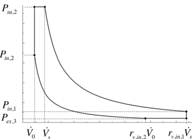
The mismatch losses due to different internal and external pressure ratios during expansion and compression are depicted in Figure 8.
Figure 8: P-V diagram of a piston expander
The model of the piston expander has been presented more in details by [27]. It introduces the clearance volume here defined as:
𝐶 = 𝑉! 𝑟!,!",!. 𝑉!
(3)
In the case where the clearance volume is equal to 0, this model could be used to describe a scroll or screw expander [22]. Table 1 proposes sets of representative values of model parameters for four different types of expansion machines. The exact meaning of the parameters could be found in [21] and [22].
Table 1: Model parameters of different expanders technologies PA R A M ETER PI STO N SC R EW OI L -FR E E SC R O L L COM P L IA NT SC R O L L fluid Water R134 a R123 R245fa 𝑉! 𝑐𝑚! 22 637 36.54 22.4 𝑟!,!",! − 7.41 4 4.05 2.85 𝑟!,!",! − 10.43 - - - 𝐶 − 0.072 - - - 𝐴!"#$ 𝑚𝑚! 1.0 15 4.6 0.68 𝑑!" 𝑚𝑚! 2.767 - 5.91 6.18 𝑑!" 𝑚𝑚! 12.9 - - - 𝑊!"##,! 𝑊 1.135. 𝑁!.!! 4700 2𝜋𝑁. 0.47 210 𝛼 − - 0.2 - 0.1
𝐴𝑈!",! 𝑊/𝐾 20 20 21 20 𝐴𝑈!",! 𝑊/𝐾 45 100 34 30 𝑀! 𝑘𝑔/𝑠 0.1 0.357 0.12 0.1 𝐴𝑈!"# 𝑊/𝐾 3.5 10 6.4 3.4
The model could be used to evaluate the impact of the different losses on the isentropic effectiveness. This is represented in Figure 9, for a simulation of a piston expander where the working fluid is water, the supply pressure is 30 bar, the supply temperature is 300°C and the rotational speed is 3500 rpm. This disaggregation indicates that the major losses are those due to the compression of the mass trapped inside the clearance volume and the internal leakages. Over-expansion losses also dramatically decrease the isentropic effectiveness in the case of over-expansion regime (low pressure ratios).
Figure 9: Impact of the different losses on the evolution of the isentropic effectiveness with the
pressure ratio
SELECTION OF EXPANDERS
The methodology shown in this paper is based on that proposed by [28], but has been extended to piston expanders.
Losses in positive displacement expanders
As indicated in the previous sections, major losses associated with expanders are: leakages, suction and discharge pressures losses, frictional, and under and over-expansion losses (and under and over-compression at the end of the discharge phase in the case of a piston expander). The former losses could be limited by a proper design of the expander, while the
latter depend on the built-in volume ratio that is a characteristic of the considered technology. The overall isentropic effectiveness can be expressed as the product of the effectiveness in the absence of volume ratio losses and the penalty associated with volume ratio mismatch:
𝜀!= 𝜀!,!"#. 𝜀!" (4) In the most general case of a piston expander, the penalty associated with volume ratio mismatch can be expressed as:
𝜀!"= 𝑤!+ 𝑤! −𝐶. 𝑟!,!",!. 𝑟!,!",!. 𝑣!" 𝑣!". 𝑤!+ 𝑤! . 1 1 − 𝐶. 𝑟!,!",!. 𝑟!,!",!. 𝑣𝑣!" !" . 1 𝑤! (5)
In the case of scroll and screw expanders, which do not show any clearance volume, 𝐶 is equal to 0.
The works 𝑤! and 𝑤! correspond to the
isentropic expansion and compression of the working fluid:
𝑤!= ℎ!"− ℎ!",! 𝑤!= ℎ!",!− ℎ!"
(6)
The works 𝑤! and 𝑤! are associated with the
losses due to under and over expansion and compression.
𝑤!= 𝑣!",!. (𝑃!",!− 𝑃!")
𝑤!= 𝑣!",!. (𝑃!"− 𝑃!",!) (7)
In the absence of mismatch losses, 𝑤!= 𝑤!= 0
and 𝜀!" gets equal to 1.
Operating maps
In the methodology proposed by [28], the choice of the expander and working fluid are done simultaneously. Moreover, the selection methodology is based on a graphical representation of operating maps. Those maps are defined in the evaporating vs condensing coordinate system, similarly to what is done for displacement compressors.
For a given expander technology and working fluid, the operating map shows a triangular shape. The upper limit corresponds to the working fluid critical temperature. The left-side limit corresponds to the criteria 𝜀!"> 0.9. The right-side limit corresponds to a constraint on
the expander size: the volume coefficient VC, defined as the ratio of the expander displacement to the delivered power, should be lower than a given limit.
Example of operating maps for a screw expander is represented in Figure 10. It was assumed that 𝜀!"> 0.9 and 𝑉𝐶 < 0.5. The maximal volume ratio is set to 5.0. For information, five typical ORC applications have been superimposed on this graph. For instance, the combination of a screw expander and R134a is suitable for a geothermal ORC.
Figure 10: Operating maps for screw expanders
Similar operating maps are shown in Figure 11 for a piston expander. Here the maximal volume ratio is set to 10.0. Also, it is assumed that 𝑤!= 0. It could be seen that piston expanders
combined with R245fa could be used for low temperature solar applications. Similar results would have been found by associating in series scroll expanders with volume ratios close to 3.0.
Figure 11: Operating maps for piston expanders
CONCLUSION
Positive displacement machines show some advantages over turbines, among them their low cost (in the eventuality of mass-production such as in HVAC), their ability to handle a liquid
phase (particularly interesting for Rankine cycle applications) and their lower rotational speeds. Today, screw expanders show a much larger technical maturity than scroll and piston expanders. The latter technologies are still limited to niche market applications characterized by small powers.
Developments of positive displacement expanders beneficiate from developments of compressors: increase of performance and reliability, extension of operating ranges, etc. It was finally shown that the selection of the expansion machine should be done simultaneously with that of the working fluid. In this paper, an existing graphical selection method, previously proposed by [28], has been extended to piston expanders. This is a useful tool for the preliminary selection of expanders and fluids for a given ORC application.
NOMENCLATURE
𝐶 clearance factor, - 𝜀 effectiveness, - 𝜑 filling factor, - ℎ specific enthalpy, J/kg 𝑟!,!" volume ratio, -𝑀 mass flow rate, kg/s 𝑃 pressure, Pa
𝑣 specific volume, m3/kg 𝑉 volume flow rate, m3/s 𝑤 specific work, J/kg 𝑊 power, W subscripts 𝑠 isentropic 𝑠𝑢 supply 𝑒𝑥 exhaust
REFERENCES
[1] R.L. Demler, The Application of the Positive Displacement Reciprocating Steam Expander to the Passenger Car. SAE. Paper 760342 (1976)
[2] J.S. Baek, E.A. Groll, P.B. Lawless, Piston-cylinder work producing expansion device in a transcritical carbon dioxide cycle. Part I: experimental investigation, Int. J. Refrigeration 28 (2005): 141-151
[3] T. Endo, S. Kawajiri, Y. Kojima, K. Takahashi, T. Baba, S. Ibaraki, T. Takahashi and M. Shinohara, Study on Maximizing Exergy in Automotive Engines. Society of
Automotive Engineers (SAE) (2007): 2007-01-0257.
[4] Seher D., T. Lengenfelder, J. Gerhardt, N. Eisenmenger, M. Hackner, I. Krinn. 2012. Waste Heat Recovery for Commercial Vehicles with a Rankine Process. 21st Aachen Colloquium Automobile and Engine Technology 2012.
[5] N. Stošić, Screw Compressors in Refrigeration and Air Conditioning. HVAC&R Research, vol 10, 3 (2004).
[6] R. McKay, International Test and Demonstration of a 1-MW Wellhead Generator: Helical Screw Expander Power Plant, Model 76-1, Final report prepared for the U.S. Department of Energy, JPL Publication 84-29, DOE/ET-37116-2 (1984). [7] R. Zanelli, D. Favrat. Experimental
Investigation of a Hermetic Scroll Expander-Generator. Proceedings 12th Internnational Compressor Engineering Conference at Purdue: (1994) 459-464.
[8] T. Yanagisawa, M. Fukuta, Y., Ogi, T. Hikichi, Performance of an oil-free scroll-type air expander: Proc. Of the ImechE Conf. on compressors and their systems (2001): 167-174.
[9] J. Elson, N. Kaemmer, S. Wang and M. Perevozchikov, Scroll Technology: An Overview of Past, Present and Future Developments (2008) Paper 1204
[10] W. Wang, Y. Wu, C. Ma, L. Liu, J. Yu, Preliminary Experimental Study of Singe Screw Expander Prototype. Applied Thermal Engineering (2011).
[11] K.C. Ng, T.Y. Bong, and T.B. Lim. A Thermodynamic model for the analysis of screw expander performance. Heat Reovery Systems & CHP Vol. 10, No2, (1990): 119-133.
[12] Brummer, Energy efficiency – waste heat utilization with screw expanders, Pumps, Compressors and Process Components, 2012
[13] Kane, M., D. Cretegny, D. Favrat, J. Maquet, Projet HTScroll, Nouveau système de cogénération à turbine spirale haute température, Rapport final, Département fédéral de l’environnement, des transports, de l’énergie et de la communication DETEC, Office fédéral de l’énergie OFEN, 29 octobre 2009.
[14] P. Platell, Displacement expanders for small scale cogeneration. Licentiate thesis. KTH (1993)
[15] S.E. Eckard, R.D Brooks, Design of reciprocating single cylinder expanders for steam, Final report, Prepared for U.S. Environmental Protection Agency, Office of Air Pollution Control, Alternative Automotive Power Systems Division, Ann Arbor, Michigan (1973)
[16] V. Lemort, I.V. Teodorese, J. Lebrun, Experimental Study of the Integration of a Scroll Expander into a Heat Recovery Rankine Cycle (2006). 18th International Compressor Engineering Conference, Purdue, USA.
[17] I.K. Smith, N. Stosic, A. Kovacevic, Steam as the working fluid for power recovery from exhaust gases by means of screw expanders, In: Proceedings of the International Conference on Compressors and their Systems, London (2009).
[18] I. H. Bell, Vincent Lemort, E. A. Groll, J. E. Braun, G. B. King, W. Travis Horton. 2012. Liquid flooded compression and expansion in scroll machines – Part II: Experimental testing and model validation. International Journal of Refrigeration, Volume 35, Issue 7, (2012): 1890-1900
[19] H. Öhman, Implementation and evaluation of low temperature waste heat recovery power cycle using HH3 in an Organic Rankine Cycle, Energy (2012), doi:10.1016/j.energy.2012.02.074
[20] Kane, El H. 2002. Intégration et optimisation thermoéconomique & environomique de centrales thermiques solaires hybrides. PhD Thesis, Laboratoire d’Energétique Industrielle, Ecole polytechnique Fédérale de Lausanne, Suisse.
[21] Lemort, V., S. Declaye and S. Quoilin. 2011. Experimental characterization of a hermetic scroll expander for use in a micro-scale Rankine cycle. Proceedings of the Institution of Mechanical Engineers, Part A: Journal of Power and Energy Volume 226 Issue 1, February 2012
[22] V. Lemort, S. Quoilin, C. Cuevas, and J. Lebrun, Testing and Modeling a Scroll Expander Integrated into an Organic Rankine Cycle, Applied Thermal Engineering (29) (2009): 3094-3102.
[23] G. Xiaojun, L. Liansheng, Z. Yuanyang, and S. Pengcheng, Research on a Scroll Expander Used for Recovering Work in a Fuel Cell, International Journal Of Thermodynamics, vol. 7, no. 1, pp. 1-8, Mar. 2004.
[24] S. Declaye, S. Quoilin, L. Guillaume and V. Lemort, Experimental study on an open-drive scroll expander integrated into an ORC system working with R245fa, paper submitted in Energy.
[25] Wang, H., R. B. Peterson, and T. Herron. 2009. Experimental performance of a compliant scroll expander for an organic Rankine cycle. Proc. IMechE Vol. 223 Part A: J. Power and Energy.
[26] K. J. Harada, Development of a Small Scale Scroll Expander, for the degree of Master of Science in Mechanical Engineering presented on September 27, 2010
[27] Y. Glavatskaya, P. Podevin, V. Lemort, O. Shonda, G. Descombes, Reciprocating Expander for an Exhaust Heat Recovery Rankine Cycle for a Passenger Car Application. Energies 5(6) (2012): 1751-1765.
[28] Quoilin S., S. Declaye, A. Legros, L. Guillaume, V. Lemort. 2012. Working Fluid Selection and Operating Maps for Organic Rankine Cycle Expansion Machines. In: Proceedings of the 21st International Compressor Engineering Conference at Purdue, West Lafayatte, USA.
![Figure 2: View of a synchronized screw expander [12]](https://thumb-eu.123doks.com/thumbv2/123doknet/6283423.164307/2.892.114.429.433.600/figure-view-synchronized-screw-expander.webp)

![Figure 4: Measured performance of an open- open-drive oil-free scroll expander (R245fa) [24]](https://thumb-eu.123doks.com/thumbv2/123doknet/6283423.164307/4.892.458.779.106.344/figure-measured-performance-open-open-drive-scroll-expander.webp)