Abstract
Conventional analysis of steel frames assumes either perfectly rigid or pinned connections. The rigidity of most connections behaves, in fact, somewhat between these two extremes. Therefore incorporating the effect of connection flexibility into the analysis and design procedure of the frame becomes necessary.
Buckling of a column is fundamental to the design of load bearing structures mainly when the analysis of such frames takes into account the effect of the connection flexibility.
The objective of this paper is to present a simplified approach for the evaluation of the elastic buckling load for steel frames with semi-rigid joints. To this end, a simple model that takes into account the effect of beam-to-column joint flexibility in the analysis of steel frames is proposed and a corresponding stiffness matrix element is presented. The model developed has been verified to be valid using an illustrative example found in the literature; numerical results are provided to illustrate the accuracy of the results.
Keywords: steel, stability, semi-rigid, connections, non sway, plane frames.
1
Introduction
In the past, the two extreme idealizations of rigid and pinned connections have been widely used in the conventional structural steel analysis and design. However, the actual behaviour of a semi-rigid connection falls between these two situations. Hence, the effect of the connection flexibility must be taken into account in the analysis and design of structures as its influence is not only to change the moment distribution among beams and columns [1-3] but also to increase the structural displacements, and in particular the P-delta second order effects [4, 5,7].
The aim of this work is to present a simplified approach for the evaluation of the elastic buckling load for steel frames considering the effect of connection flexibility, from which a corresponding stiffness matrix is proposed [6].
Paper 2
Stability of Non-Sway Steel Frames with Semi-Rigid
Connections
A.N.T. Ihaddoudène
2and J.P. Jaspart
2 1Built Environment Research Laboratory
Faculty of Civil Engineering, U.S.T.H.B., Algiers, Algeria
2Faculty of Applied Sciences, Department ArGEnCo
Liège University, Belgium
©Civil-Comp Press, 2013
Proceedings of the Fourteenth International Conference on Civil, Structural and Environmental Engineering Computing, B.H.V. Topping and P. Iványi, (Editors),
2
Mechanical model
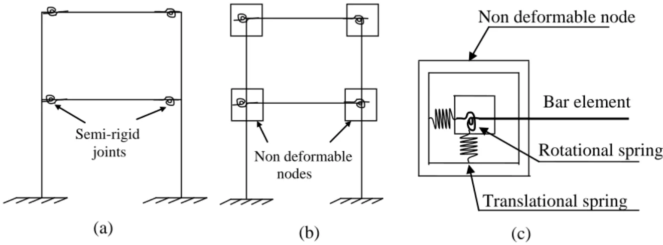
To incorporate the effect of semi-rigid joints in the analyses of the steel frame shown in Figure 1a, the concept of a non-deformable node element describing relative displacements and rotations between the elements of the structure (see Figure 1b) is introduced [1-3]. The adopted model shown in Figure 1c is based on the use of three springs: two translational ones and rotational one.
(a): Semi-rigid joints; (b): Non deformable node; (c): Bar element and non deformable node.
Figure 1: Mechanical model adopted.
2.1 Stiffness matrix
The stiffness matrix that relates the element end forces to end displacements is formulated for all members with semi-rigid connections of the frame. The corresponding elastic buckling load is then obtained by setting the determinant of the stiffness matrix of the whole frame to zero. To establish the modified stiffness matrix including both the effect of axial force and connection flexibility [6], different situations are considered.
In the local reference, the stiffness matrix of a structural bar element is given by:
= 44 43 42 41 34 33 32 31 24 23 22 21 14 13 12 11 k k k k k k k k k k k k k k k k Ke (1)
The nodes of the beam which are represented by non deformable frames at each ends [1-3] have different flexibilities k1 and k2 at both ends i and j respectively. In order to establish the different elements of the stiffness matrix Kein local
(c) Non deformable nodes (b) Semi-rigid joints (a) Bar element Rotational spring Translational spring Non deformable node
reference, equilibrium equations and rotational deformations are considered for each element kij.
3
Buckling considerations
The system of equilibrium equation is now expressed in the deformed state of the bar element, which connections are semi-rigid. Here, the effects of semi-rigid joints on the elastic buckling load of steel frames are studied [6]. Let consider the bar element with semi-rigid joints in Figure 2, subjected to both a compression axial forcesN and bending moments M and i M at each ends. j
In order to express the termsk1jof the stiffness matrix, a column with semi-rigid
joints is considered and the equilibrium equations are expressed as: H H Hi = j = (2) j x Ny Hx M M = + − (3) j i N Hl M M = + − (4)
The governing differential equation is given as follows: Figure 2: Bar element under unit displacement ∆i =1
1 = ∆i i M j M 1 k 2 k N i H j H N l x y
j M Hx Ny x EIy"( )=− − + (5) Introducing EI N = 2 α (6) EI M Hx y x y"( )+α2 =− − j (7) the general solution of Equation 5 is:
p y x B x A x y( )= cosα + sinα + (8) Wherey , A and B are respectively the particular solution and integration p constants to be determined using the boundary conditions at the ends supports:y(0)
and y(l):
[
]
EI M EI Hx x EI M EI Hl l M l EI x x y 2 j(cos 1) 2 2 j cos 2 2 j sin sin ) ( α α α α α α α α α − + + − − + = (9)and the derivative:
[
]
EI Hx x EI M EI Hl l M l EI x x y 2 j(cos 1) 2 2 j sin 2 sin cos ) ( ' α α α α α α α α α α − + + + − = (10)The reactions H ,Miand M are determined by using the boundary conditions ofj
) ( ' ) 0 ( ' and y l
y and the solutions of this system of equations is obtained as:
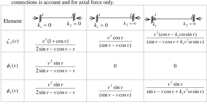
) ( 2 2 v l H = ω ζ (11) ) ( 3 v l Mj =ωφ (12) ) ( 4 v l Mi =ωφ (13) Table 1 below summarizes the expressions for different support conditions from which the terms of the element matrix stiffness may be derived.
Table 2 below consider these two situations shows the difference in the expressions of the element stiffnessk1j in two cases: for both axial force and semi-rigid connections is account and for axial force only.
Element ) ( 2 v ζ v v v v v v − − + cos sin 2 ) cos 1 ( 3 ) cos (sin cos 3 v v v v v
− (sin cos sin )
) sin (cos 2 1 1 3 v v k v v v v v k v v ω ω + − − ) ( 3 v φ v v v v v v − − cos sin 2 sin 2 0 0 ) ( 4 v
φ 2sinvv− cossinv v v−v
2 ) cos (sin sin 2 v v v v v
− sin cos sin )
sin 2 1 2 v v k v v v v v ω + −
Table 1: Different types of supports
j
k1 Axial force and semi-rigid
Connections considered Axial force considered
11 k D v v l EI (sin ) . 3 3 Ω + ) sin cos 2 2 ( sin . 3 3 v v v v v l EI − − 12 k D v v l EI (1 cos ) . 2 2 2 η + − − ) sin cos 2 2 ( ) cos 1 ( . 2 2 v v v v v l EI − − − − 13 k D v v l EI 3(sin ) 3 Ω + − ) sin cos 2 2 ( sin . 3 3 v v v v v l EI − − − 14 k D v v l EI (1 cos 1) 2 2 η + − ) sin cos 2 2 ( ) cos 1 ( . 2 2 v v v v v l EI − − −
Table 2: k1j expressions in several situations. In Table 2: l v=α (14) l I E = ω (15) i 0 1 = k k2 =∞ j i 1 k k2 =∞ j j i 0 1 = k k2 =0
) , , ( ) sin cos 2 2 ( v v v v k1 k2 D= − − +ξ (16) v vw k k v vw k k ) cos ( ) sin ( 1 + 2 − 1 2 2 = Ω (17) v vw k1 sin 1 = η (18) v vw k2 sin 2 = η (19)
The same procedure is used to derive all the components of the matrix. The elastic buckling load for the frame is hence then obtained, by setting the determinant of the structure stiffness matrix to zero.
4
Example
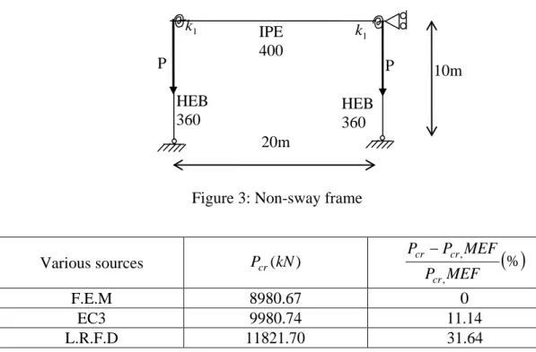
The developed procedure is applied to the simple steel non-sway frame illustrated Figure 3.
The following example is taken from the previously published paper [8], for which the proposed approach is demonstrated and the results compared and validated. The characteristics of the elements are given below:
For the beam
= = kN EA m kN EI 896490 . 48573 2
and for the column
= = kN EA m kN EI 1272600 . 90699 2 and the flexibility k1 =1/150rad/kN.m
Table 3 gives the values of the critical load according to different sources.
Various sources Pcr(kN)
( )
% , , MEF P MEF P P cr cr cr − F.E.M 8980.67 0 EC3 9980.74 11.14 L.R.F.D 11821.70 31.64 P 1 k 20m IPE 400 P HEB 360 HEB 360 1 k 10mReference [8] 8980.67 0 Present proposed study 8980 .6 −0.0008
Table 3: Comparison of the critical load values
The results obtained by this analytical formulation are clearly consistent with those obtained by reference [8] and by the finite element method, whereas the application of the European and American codes gives different values.
5
Conclusions
The influence of connection flexibility on the stability of non-sway steel frames is investigated and a simple method of analysis and design is provided through a mechanical model for the joints.
A modified stiffness matrix using analytical expressions for steel frames with semi-rigid connections subjected to axial loads, have been derived for the calculation of the elastic buckling load.
An illustrative example compares results obtained with numerical methods, codes and the present study. It gives similar values than those published in [8], which is demonstrating its efficiency. The use of two international codes gives different values.
References
[1] A.N.T. Ihaddoudène, M. Saidani, M. Chemrouk, “Modelling of steel frames with semi-rigid joints”. International Journal of Applied Engineering Research, 3(7), 955-67, 2008.
[2] A.N.T. Ihaddoudène, M. Saidani, M. Chemrouk, “Mechanical model for the analysis of steel frames with semi-rigid joints”, Journal of Constructional Steel Research, 65(3), 631-40, 2009.
[3] A.N.T. Ihaddoudène, M. Chemrouk, “ Influence of Semi-Rigid Joints on the Behaviour of Steel Beam-Column Structures”, Proceedings of the International Conference on Computational & Experimental Engineering & Science, paper N°.249, Madeira, 2004.
[4] D. Conception, P. Marti, M.Victoria, O.M. Querin, “Review on the modelling of joint behaviour in steel frames”, Journal of Constructional Steel Research, 67(5), 741-58, 2011.
[5] J.P. Jaspart, “Etude de la semi-rigidité des nœuds poutre-colonne et son influence sur la résistance et la stabilité des ossatures en acier”, Ph.D. Thesis, University of Liège, Belgium, 1991.
[6] A.N.T. Ihaddoudène, “Analyse de la stabilité des structures à assemblages semi-rigides”, Ph.D Thesis, Faculty of Civil Engineering, University of Sciences and Technology, U.S.T.H.B, Algeria, 2008.
[7] I.G. Raftoyiannis, “The effect of semi-rigid joints and an elastic bracing system on the buckling load of simple rectangular steel frames”, Journal of Constructional Steel Research, 61(9), 1205- 25, 2005.
[8] G.E. Mageirou, C.J. Gantes, “Buckling strength of multi-story sway, non-sway and partially-sway frames with semi-rigid connections”, Journal of Constructional Steel Research, 62(9), 893-905, 2006.