Analysis Of Induction Motor With Broken Bars And Constant Speed Using Circuit-field Coupled Method
15
0
0
Texte intégral
(2) N. Halem et al.. J Fundam Appl Sci. 2011, 3(1), 111-125. 112. The modeling with finite element method represents a high fidelity electromagnetic behavior. Which leads to more precise results than other models, as the actual geometry and winding layout of the machine are used? The consideration of the behaviour of the local electromagnetic induction machine provides a more accurate modeling. The numerical solution of Maxwell’s equations governing the behavior of electromagnetic fields and the consideration of the equations representing the electrical supply circuit of the machine reduces the simplifications made in the classical models. In analysis of induction motors, the input current, not the voltage, is usually used. The voltage source which is mainly discussed is usually used. The voltage source which is mainly discussed in this paper is more suitable than current source. The external circuit that represents the electrical sources and circuit components are coupled to the FEM. Only the terminal voltages applied to the motor are required as known input quantities, and the total terminal currents are the unknowns to be evaluated. The use of time-stepping finite elements is the most precise way, up to date, for modeling the coupled field-circuits and motion of induction motors, accounting for space harmonics [3]-[6]. This paper represents the transient state modeling of cage induction motors using the coupled electric circuit with 2D finite element electromagnetic field analysis. The Ansys magnetic analysis software is used for calculating the magnetic field of an induction motor for the normal rotor, and for broken bars. 2. FINITE ELEMENT MODEL APPLIED TO THE ASYNCHRONOUS MACHINE Generally, the electric machine and apparatus are excited by connecting the external constant power source. Thus, it is necessary that the characteristics will be calculated under the constant terminal voltage. In this paper, the three-phase induction motor is analyzed by finite element method taking into account the terminal voltage. All the stator and rotor slots are represented in the circuit domain by defining real constants to conductor area in the FE domain. The motor is excited to its rated voltage and frequency using a three-phase voltage source..
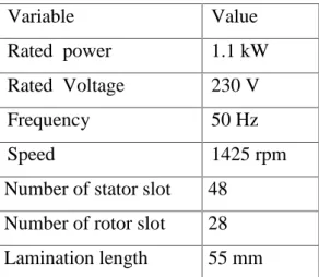
(3) N. Halem et al.. J Fundam Appl Sci. 2011, 3(1), 111-125. 113. Table 1. Characteristics of the machine Variable. Value. Rated power. 1.1 kW. Rated Voltage. 230 V. Frequency. 50 Hz. Speed. 1425 rpm. Number of stator slot. 48. Number of rotor slot. 28. Lamination length. 55 mm. The Fig. 1 shows the stator electric circuit model, the CIRCU124 elements are an intermediate between the magnetic circuit of the stator and the external electric circuit using the coupling commands. For the FE magnetic circuit model as shown in Fig. 2, both stator and rotor magnetic circuits are modeled with type PLANE53 element. The stator slots containing the coil, are modeled by using the type PLANE53 element option KEYOPT (1) = 3, the squirrel cage bars are modeled with the type PLANE53 option KEYOPT (1) = 4. In the present work the bars are coupled to the end ring resistance through the massive conductor circuit element which is an intermediate element between the F.E regions and the external circuits, the end ring inductance is neglected. As illustrate in the Fig. 3, the squirrel-cage rotor of the study motor has 28 bars connected at both ends through endring connectors resistance, the other end of the massive conductor circuit element is connected to a small resistance which stands for the bar portion which is not laid down the stator field, all these resistances are connected to a common point having zero volt boundary [15]..
(4) N. Halem et al.. J Fundam Appl Sci. 2011, 3(1), 111-125. Voltage source. 114. Coupled stator coil winding elements. Fig.1. Stator electric circuit model Stator winding coupled to the FE model. Fig.2. FE Magnetic circuit model. End-ring resistance. Rotor bars coupled to the FE model. Coupled rotor bar elements Fig.3. Rotor electric circuit model.
(5) N. Halem et al.. J Fundam Appl Sci. 2011, 3(1), 111-125. 115. A detail of the mesh used for simulation is shown in Fig. 4, as illustrated in the region of the gap is geometrically divided into two equivalent regions, the first is related to the stator, called stator-air, and the second region connected to the rotor, called rotor-air, so the middle of the gap there are two lines that occupy the same space, the first line is related to stator-air region, while the second line is related to rotor-air region. Note that these two regions of the gap must be meshed separately.. Stator_air. Rotor_air. Fig.4. Finite element meshes The rotor air is joined to the stator with stator air by using coupling equations. The elements belong the outer line of the rotor air and the nodes belong the inner stator air is coupled together by using the coupled command. After the coupling, the rotor can rotate with any angle as your wish. Though this process, the mesh sizes of the moving meshes in the air gap are changed to accomplish the nodal connectivity to the adjacent meshes. At the adjacent, the slip boundary is established. Once the magnetic field is determined by the time-stepping finite-element method, the magnetic force and torque are calculated by using the Maxwell stress tensor. Then mechanical motion is solver by the Runge-Kutta method. After the mechanical equation determines a new angular and radial position of a rotor, the finite-element model is rearranged by moving mesh technique to recalculate the magnetic field [15]. There are two types of motion for a specific analysis of the induction motor: Rotor rotation at constant angular velocity. For the constant speed motion, the rotor speed is specified in rpm. This time stepping scheme allows us to model the motor at the speed where there are harmonic problems..
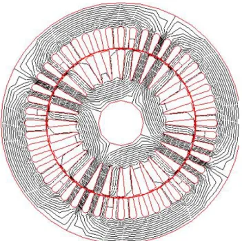
(6) N. Halem et al.. J Fundam Appl Sci. 2011, 3(1), 111-125. 116. Rotor motion is governed by the mechanical equation. This time stepping scheme, coupled with the mechanical equation, allows us to model such transient dynamic behavior of the induction motor as the start up or motor operating condition after a load modification. In this paper, the induction motor is simulated by using type1 under rated conditions. For a given constant speed, an electrical cycle is divided into 72 discrete steps. In each time step, the coupling equations of the slide boundary are cleared. Then the rotor is rotated by 5 degrees and rebuilding the new coupling equations on the slide boundary. In the first time step, a static analysis is performed to establish the initial magnetic field. The initialized time is 0 second (actually using 10-9 as ANSYS does not allow 0 as a time step) [15]. 3.. SIMULATION RESULT WITH CONSTANT SPEED AND LINEAR MAGNETIC MATERIAL. Fig. 5 shows the magnetic field distribution at steady state for healthy rotor. When the slip is small, the eddy current in the secondary conductor is small either. Therefore, the flux passes through the inside of rotor because of small effect of the field caused by eddy current. But above this, the results show that flux distribution is symmetrical in each pole.. Fig.5. Magnetic field distribution.
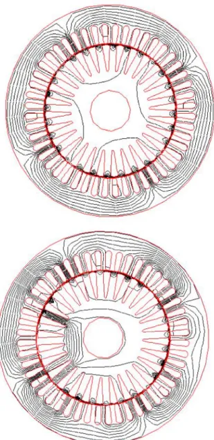
(7) N. Halem et al.. J Fundam Appl Sci. 2011, 3(1), 111-125. 117. Fig. 6 shows the magnetic flux distribution of a rotor cage with 5 broken bars at the transient state. When the slip is large, the eddy current shows a large value. This high value of slip is necessary to illustrate the effects of the broken bars on the field. The concentration of magnetic flux is observed around the broken bar and creates asymmetric magnetic flux distribution [7]-[9].. Fig.6. Magnetic flux distribution at the transient state Top: Healthy rotor, Bottom: 5 broken bars.
(8) N. Halem et al.. J Fundam Appl Sci. 2011, 3(1), 111-125. 118. One can notice that the region around the broken bar of the rotor has a higher degree of saturation in comparison to the same region with no broken bars [10]. This is due to the fact that in the broken bar region there is no localized conductor demagnetization effect since these bars carry no currents [11].. a) Healthy state. 3 2.5 2. Radial flux density (T). 1.5 1 0.5 0. -0.5 -1. -1.5 -2 -2.5 -3 0. 50. 100. 150. 200. 250. 300. 350. Air gap (mm). b) Rotor with 5 broken bars. 3 2.5. Radial flux densitry (T). 2 1.5 1 0.5 0 -0.5 -1 -1.5 -2 -2.5 -3 0. 50. 100. 150. 200. 250. 300. 350. Air gap (mm). Fig.7. Waveform of the air gap flux density Fig. 7 shows the waveform of the air gap flux density along a circular contour in the airgap. The flux densities have a symmetrical distribution in healthy state. The perturbation in the magnetic field produced by 5 broken bars results in a non symmetrical field [12]..
(9) N. Halem et al.. J Fundam Appl Sci. 2011, 3(1), 111-125. 119. 4. SPECTRUM ANALYSIS OF STATOR CURRENT An induction machine rotor asymmetry introduced by broken bars produces spectrum lines of stator current at frequencies:. f bb1 f s (1 2ks). (1). Where fs is the electrical supply frequency, s is the slip, k=1, 2, 3…, respectively. In fig. 8, the spectra of the simulated stator current with healthy rotor and with 5 broken bars are represented. In case of broken rotor bar, the rotor is electrically asymmetric and the backward rotating field is created. The current spectrum reveals sidebands expected around the supply frequency given by (1) [13]-[14]. 0 -10. Magnitude (dB). -20 -30 -40 -50 -60 -70 -80 -90 0 0. 5 10 15 20 25 30 35 40 45 50 55 60 65 70 75 80 85 90 95 100 Frequency (Hz). -10. Magnitude (dB). -20. f bb1 f s (1 2ks ). -30 -40 -50 -60 -70 -80 -90 0. 5 10 15 20 25 30 35 40 45 50 55 60 65 70 75 80 85 90 95 100 Frequency (Hz). Fig.8. Simulated current spectrum, a) Healthy rotor, b) Rotor with 5 broken bars.
(10) N. Halem et al.. J Fundam Appl Sci. 2011, 3(1), 111-125. 120. In order to have a better understanding of rotor broken bar, it may be necessary to examine the higher frequency components of the frequency spectra. When we took into account the space harmonics, additional frequencies given by:. k f bb 2 f s (1 s ) s p . (2). Where p is the number of pole pairs and k/p=1,3,5, … 0 -10. Magnitude (dB). -20 -30 -40 -50 -60 -70 -80 -90 0. 50. 100 150 200 250. 300 350 400 450 500. 550 600 650 700 750. 800. Frequency (Hz). Fig.9. Simulated current spectrum with healthy rotor 0 -10 Magnitude (dB). -20 -30 -40 -50 -60 -70 -80 -90 0. 50. 100 150. 200 250 300. 350 400 450. 500 550 600. 650 700 750. 800. Frequency (Hz). Fig.10. Simulated current spectrum with 5 broken bars. The spectra of the stator current of the machine when it runs in healthy conditions are shown in Fig. 9. The spectra of the stator current of machine when it runs in faulty.
(11) N. Halem et al.. J Fundam Appl Sci. 2011, 3(1), 111-125. 121. conditions are shown in Fig. 10. It is obvious that besides the supply frequency component, higher frequency components exist around the principal slot harmonics and around some frequency components (150 Hz, 250Hz, 350Hz…) as was predicted. The stator current frequency described by (1) and (2) can be detected over the observation bandwidth between 0 Hz and 1000 Hz.. 5. EXPERIMENTAL RESULTS In order to validate the simulation results, a special test model was used. It is a 1.1kW 220/380V 50Hz four pole induction motor whose stator windings were modified in order to have accessible several tapping. That can be used to introduce inter-turn short circuits with different number of turns. This test bench is available at the LAII in Poitiers, France. The spectrum of Fig. 11 shows the measured current waveform spectra with healthy rotor and with two broken bars. The current spectrum reveals sidebands expected around the supply frequency. Even for a motor in a healthy state, there are always frequency components but of low amplitudes, this is due to the natural asymmetry of the motor, and on the other hand from the power supply (distortion in the power supply voltage waveform). As can be clearly seen through Fig. 12, the occurrence of two broken rotor bar increases significantly the magnitudes of several sidebands around the fundamental. 0 -10. Magnitude (dB). -20 -30 -40 -50 -60 -70 -80 0. 10. 20. 30. 40 50 60 Frequency (Hz). 70. 80. 90. Fig.11. Measured current spectrum with healthy rotor. 100.
(12) N. Halem et al.. J Fundam Appl Sci. 2011, 3(1), 111-125. 122. 0 -10. Magnitude (dB). -20 -30 -40 -50 -60 -70 -80 0. 10. 20. 30. 40 50 60 Frequency (Hz). 70. 80. 90. 100. Fig.12. Measured current spectrum with two broken bars The spectrum of Fig. 13 shows the measured current waveform spectra with healthy rotor. We notice the presence of the slot harmonics in addition to the harmonics due to saturation. The lower rotor slot harmonic is visible at 620 Hz. As envisaged during simulation, we show the presence of the harmonics components of high frequencies. In order to avoid any misinterpretation, all spectral components having magnitudes less than -70 dB are assumed as noise.. 0 -10. Magnitude (dB). -20 -30 -40 -50 -60 -70 -80 0. 100. 200. 300 400 Frequency (Hz). 500. Fig.13. Measured current spectrum. 600. 700.
(13) N. Halem et al.. J Fundam Appl Sci. 2011, 3(1), 111-125. 123. 0. Magnitude (dB). -10 -20 -30 -40 -50 -60 -70 -80 0. 100. 200. 300 400 Frequency (Hz). 500. 600. 700. Fig.14. Measured current spectrum with two broken bars Furthermore, the Fig. 14 shows, clearly, considerable changes in magnitude for the sidebands around the 3rd, 5th and 7th current time harmonics, for a motor with two broken bars.. 6. CONCLUSION This paper presents the circuit coupled finite element method used to modeling the Three-Phase Squirrel Cage Induction Motor. For this purpose, the time-stepping finite element method (TSFE) was proposed. The determination of magnetic flux density waveform, magnetic flux distribution was obtained. The perturbation in the air-gap magnetic field produced by broken bars results in a non-symmetrical field. The simulation with constant speed and linear magnetic materials was used in order to eliminate their influence. As envisaged during simulation, the presence of harmonic in current spectra at low and high frequency confirm the experimental results, proving that the proposed approach constitutes a useful tool for the study and diagnostics of induction motors. It will be mentioned that this approach is limited only to the evaluation of the component frequencies induced by the broken bars fault.. 7. ACKNOWLEDGEMENTS The authors would like to thank Professor Champenois at the LAII laboratory, Poitiers, France, for his help..
(14) N. Halem et al.. J Fundam Appl Sci. 2011, 3(1), 111-125. 124. 8. BIBLIOGRAPHY [1] A. Ghoggal, M. Sahraoui and S.E. Zouzou, “Analytical and experimental study of a squirrel cage induction motors with rotor bar faults”, Advances In Modeling, Measurement And Control, A : General Physics And Electrical Applications, AMSE, vol. 81, no. 2, pp. 43-60, 2008. [2] S. E. Zouzou, A. Ghoggal, A. Aboubou, M. Sahraoui, and H. Razik, “Modelling of induction machines with skewed rotor slots dedicated to rotor faults”, presented at the IEEE International Symposium on Diagnostics for Electric Machines, Power Electronics and Drives, Vienna Austria, 7-9 Sep. 2005. [3] Y. Ouazir, N. Takrobat, R. Ibtiouen, and M. Benhaddadi, “Time-stepping FE analysis of cage induction motor with air-gap interface coupling taking into account phase-belt harmonics “, IEEE trans. Magn, Vol. 45, pp. 1384-1387, Mar. 2009. [4] J. Faiz, B. M. Ebrahimi, And M. B. B. Sharifian, “Time stepping finite element analysis of broken bars fault in a three-phase squirrel-cage induction motor”, Progress in Electromagnetic Research, Vol. 68, pp. 53-70, 2007. [5] J. F. Bangura, N. A. Demerdash, “Diagnosis and characterization of effects of broken bars and connectors in squirrel-cage induction motor by time-stepping coupled FE state space modeling approach”, IEEE Trans. Energy Convers, Vol. 14, pp. 11671176, Apr. 1999. [6] X. Ying, “Characteristic performance analysis of squirrel cage induction motor with broken bars”, IEEE trans. Magn, Vol. 45, pp. 759-766, Feb. 2009. [7] R. Fiser, S. Ferkolj, “Application of a finite element method to predict damaged induction motor performance”, IEEE Trans. Magn, Vol. 37, part 1, pp. 3635-3639, September 2000. [8] G. H. Jang, S. J. Park, “Simulation of the electromechanical faults in a single-phase squirrel cage induction motor”, Ieee Trans, Magn, Vol. 39 pp. 2618-2620, Sep 20003. [9] C. J. Aileen, S. Nagarajan and S. R. Reddy, “Detection of broken bars in three phase squirrel cage induction motor using finite element method”, presented at the International Conference on Emerging Trends in Electrical and Computer Technology (ICETECT), Nagercoil, India, 23-24 Mars 2011. [10] J. Spoorten, J. C. Maun, “Influence of saturation level on the effect of broken bars in induction motors using fundamental electromagnetic laws and finite element simulations”, IEEE Trans. Energy Convers, Vol 24, pp 557-564, Sep 2009..
(15) N. Halem et al.. J Fundam Appl Sci. 2011, 3(1), 111-125. 125. [11] L. Weili, X. Ying, S. Jiafeng, L. Yingli, “Finite element analysis of field distribution and characteristic performance of squirrel-cage induction motor with broken bars” Ieee Trans. Magn, Vol 43, pp 1537-1540, Apr 2007. [12] K. J. Hammadi, D. Ishak, and W. Salah, “Rotor fault diagnosis based on current signatures in squirrel-cage induction motor”, presented at the International Conference on Electronic Devices, Systems and Applications (ICEDSA), Kuala Lumpur, Malasya, pp. 200-205, 11-13 Apr 2010. [13] M. Riera-Guasp, M. F. Cabanas, « Influence of nonconsecutive bar breakages in motor current signature analysis for the diagnosis of rotor faults in induction motor », IEEE Trans. Energy Convers, Vol 25, pp. 80-89, March 2010. [14] J. Faiz, B. M. Ebrahini, “Locating rotor broken bars in induction motors using finite element method”, Energy Conversation and Management, Vol, 50, pp. 125-131, Jan 2009. [15] N. Tong, F. Zhang, J. Wang, "Analysis of Single- Phase Induction Motor by Using Circuit Coupled Finite Element Method", International Conference On Electrical Machines and Systems,(ICEMS), 17-20 , pp. 4127-4130, Oct 2008.. How to cite this article Halem N, Zouzou S E and Srairi K. Analysis of induction motor with broken bars and constant speed using circuit-field coupled method. J Fundam Appl Sci. 2011, 3(1), 111-125..
(16)
Figure

Documents relatifs
Fatty liver with no evidence of liver cell necrosis (ballooning) or fibrosis (bridging): Low risk for cirrhosis or liver failure – Non-alcoholic fatty liver
The compressibility property of the Fermi gas in the ground state (i.e. 0 is due to the finite magnetization of Landau subbands at rational flux. An explicit and
We will further consider the case where magnetic field does not have influence in the applications studied in this paper, so that it can be dropped from subsequent
To overcome these problems, two intelligent control theories, including fuzzy logic control (FLC) and neuro-fuzzy control (NFC) are introduced to replace the
Abstract: The fault of broken rotor bars in a three phase induction motor is diagnosed by using the wavelet Packet analysis. In this paper Daubechies wavelet is selected as the
Abstract: The fault of broken rotor bars in a three-phase induction motor is diagnosed by using the wavelet Packet analysis. In this paper Daubechies wavelet is selected as the
From this point of view, the concept of a “positive” or "negative” test is insufficient (and sometimes even unsuitable) and the interpretation must consider both
Here we show that five distinct fibrillar a-Syn polymorphs (Fibrils, Ribbons, Fibrils-91, Fibrils-65 and Fibrils-110) bind to and cluster differentially at the
