THÈSE
THÈSE
En vue de l’obtention du
DOCTORAT DE L’UNIVERSITÉ DE TOULOUSE
Délivré par : l’Université Toulouse 3 Paul Sabatier (UT3 Paul Sabatier)Présentée et soutenue le 17/01/2018 par :
Nicolas STAUB
Models, Algorithms and Architectures for
Cooperative Manipulation with Aerial and Ground Robots
JURY
Anibal OLLERO Professeur Rapporteur
Philippe FRAISSE Professeur Rapporteur
Sandra HIRCHE Professeur Examinateur
Simon LACROIX Directeur de Recherche Examinateur
Paolo ROBUFFO GIORDANO Directeur de Recherche Examinateur
Antonio FRANCHI Chercheur CNRS Directeur de thèse
École doctorale et spécialité : EDSYS : Robotique 4200046 Unité de Recherche :
Laboratoire d’Analyse et d’Architecture des Systèmes (LAAS–CNRS) Directeur de Thèse :
Antonio FRANCHI Rapporteurs :
Acknowledgments
First, I would like to express my sincere gratitude to Dr. Antonio Fanchi, my thesis supervisor, for his guidance and availability during the course of my PhD. His work dedication and enthusiasm was a daily inspiration. A warm thanks also go to the LAAS– CNRS, my hosting lab, and its people, in particular to the RIS group for making this research possible and providing a fantastic work environment.
I would like to thank the jury members for taking part in my defense and providing stimulating questions and discussions about my work and its perspectives. In particular, I am most grateful to the two reviewers, Pr. Anibal Ollero and Pr. Philippe Fraisse, for their invaluable feedbacks on my work.
I would like to express my deepest gratitude to Pr. Dongjun Lee, for hosting me six months at Seoul National University in South Korea. This stay was a life experience both from the research perspective and from the personal one. I would also thank all the students from the INROL lab for their warm welcome and their help to settle. In particular Hyunsoo and Changsu for their kindness and guidance.
This journey would not have been the same without all the people around. A warm thanks goes to Matthieu Herrb and Anthony Mallet for their constant support and guidance. My warmest thanks go to Marco, for all the insightful discussions but also for all the moments in and out the lab that we shared. I am deeply in debt to Burak as well, for his guidances and enthousiam during our joint work at the beginning of my PhD life and for his warm friendship. My gratitude also goes towards Davide for is invaluable work and support during our joint project, especially the insane rush toward Hanover. I want to thank Quentin for sharing French humor with me during the most stressful part of my PhD and for his dedication to making things work. I would also like to express my gratitude to all the other students met other the years, for more or less serious discussions. Special thanks go to Kevin, Cécile and Aïva for the invaluable coffee breaks and discussions.
I would take the opportunity to thank everyone from the KUKA 2017 Innovation Award, which made the Tele-MAGMaS demonstration possible. The KUKA IA team for their unwavering support during the installation week in Hanover. All the members of the Tele-MAGMaS team for being part of it and for their contributions. Especially those present in Hanover for the installation and demonstration. My sincere gratitude goes to Mostafa who managed to finish is PhD concurrently to being heavily involved in the project.
Lastly, I would like to express my deepest gratitude to my family and friends for their support and encouragements in this journey. My parents for their unconditional love and for transmitting me this eagerness toward sciences and techniques, always supporting it. My brother for the jokes and discussions we shared along the way. My friends, in and out of the lab, who were around and oversaw my PhD life, their constant support and encouragements proved invaluable. I would like to thank my flatmates for being there every day, especially Pierrick with whom I navigated the PhD life.
And of course the last word for Franzi, who provides sparkles in my life and an oasis of calm when it is most needed, thank you for being on my side.
Abstract
In recent years, the subject of physical interaction for aerial robots has been a pop-ular research area with many new mechanical designs and control approaches being proposed. The aerial robotics community is currently observing a paradigm shift from classic guidance, navigation, and control tasks towards more unusual tasks, for example requesting aerial robots to physically interact with the environment, thus extending the manipulation task from the ground into the air. This thesis con-tributes to the field of aerial manipulation by proposing a novel concept known has
Multiple Aerial-Ground Manipulator System or MAGMaS, including what appears
to be the first experimental demonstration of a MAGMaS and opening a new route of research.
The motivation behind associating ground and aerial robots for cooperative manipulation is to leverage their respective particularities, ground robots bring strength while aerial robots widen the workspace of the system. The first contribu-tion of this work introduces a meticulous system model for MAGMaS. The system model’s properties and potential extensions are discussed in this work. The plan-ning, estimation and control methods which are necessary to exploit MAGMaS in a cooperative manipulation tasks are derived. This works proposes an optimal control allocation scheme to exploit the MAGMaS redundancies and a general model-based force estimation method is presented. All of the proposed techniques reported in this thesis are integrated in a global architecture used for simulations and experi-mental validation. This architecture is extended by the addition of a tele-presence framework to allow remote operations of MAGMaS. The global architecture is vali-dated by robust demonstrations of bar lifting, an application that gives an outlook of the prospective use of the proposed concept of MAGMaS. Another contribution in the development of MAGMaS consists of an exploratory study on the flexibil-ity of manipulated loads. A vibration model is derived and exploited to showcase vibration properties in terms of control.
The last contribution of this thesis consists of an exploratory study on the use of elastic joints in aerial robots, endowing these systems with mechanical compli-ance and energy storage capabilities. Theoretical groundings are associated with a nonlinear controller synthesis. The proposed approach is validated by experimental work which relies on the integration of a lightweight variable stiffness actuator on an aerial robot.
Keywords
Cyber-physical systems – Aerial manipulation systems – Shared control – Non-linear control and estimation – Manipulation with compliant actuators
Résumé
Les dernières années ont vu le développement de recherches portant sur l’interaction physique entre les robots aériens et leur environnement, accompagné de l’appari-tion de nombreux nouveaux systèmes mécaniques et approches de régulal’appari-tion. La communauté centrée autour de la robotique aérienne observe actuellement un dé-placement de paradigmes des approches classiques de guidage, de navigation et de régulation vers des tâches moins triviales, telle le développement de l’interaction physique entre robots aériens et leur environnement. Ceci correspond à une exten-sion des tâches dites de manipulation, du sol vers les airs. Cette thèse contribue au domaine de la manipulation aérienne en proposant un nouveau concept appelé MAGMaS, pour « Multiple Aerial Ground Manipulator System ».
Les motivations qui ont conduites à l’association de manipulateurs terrestres et aériens pour effectuer des tâches de manipulation coopérative, résident dans une volonté d’exploiter leurs particularités respectives. Les manipulateurs terrestres ap-portant leur imap-portante force et les manipulateurs aériens apap-portant leur vaste es-pace de travail. La première contribution de cette thèse présente une modélisation rigoureuse des MAGMaS. Les propriétés du système ainsi que ses possibles exten-sions sont discutées. Les méthodes de planning, d’estimation et de régulation néces-saire à l’exploitation des MAGMaS pour des tâches de manipulation collaborative sont dérivées. Ce travail propose d’exploiter les redondances des MAGMaS grâce à un algorithme optimal d’allocation de forces entre les manipulateurs. De plus, une méthode générale d’estimation de forces pour robots aériens est introduite. Toutes les techniques et les algorithmes présentés dans cette thèse sont intégrés dans une architecture globale, utilisée à la fois pour la simulation et la validation expéri-mentale. Cette architecture est en outre augmentée par l’addition d’une structure de télé-présence, afin de permettre l’opération à distances des MAGMaS. L’archi-tecture générale est validée par une démonstration de levage de barre, qui est une application représentative des potentiels usages des MAGMaS. Une autre contribu-tion relative au développement des MAGMaS consiste en une étude exploratoire de la flexibilité dans les objets manipulés par un MAGMaS. Un modèle du phénomène vibratoire est dérivé afin de mettre en exergue ses propriétés en termes de contrôle. La dernière contribution de cette thèse consiste en une étude exploratoire sur l’usage des actionneurs à raideur variable dans les robots aériens, dotant ces sys-tèmes d’une compliance mécanique intrinsèque et de capacité de stockage d’énergie. Les fondements théoriques sont associés à la synthèse d’un contrôleur non-linéaire. L’approche proposée est validée par le biais d’expériences reposant sur l’intégration d’un actionneur à raideur variable léger sur un robot aérien.
Mots Clés
Systèmes cyber-physiques – Système de manipulation aérienne – Commande partagée – Commande et observateur non-linéaires – manipulation avec actionneur souple
Contents
Acknowledgments i Abstract iii Résumé v Contents vii List of Figures xiList of Tables xiii
List of Multimedia xv
List of Acronyms xvii
I Preliminaries 1
1 Contribution and Overview 3
1.1 Contributions . . . 3
1.2 Organization . . . 5
2 State of the Art in Aerial Physical Interaction 7 2.1 Motivations . . . 7
2.2 Aerial Physical Interaction Paradigms . . . 10
2.2.1 Original Mechanical Designs . . . 10
2.2.2 Applications . . . 11
2.3 Design of Aerial Manipulators . . . 12
2.3.1 Flying Platform Designs . . . 13
2.3.2 Embedded Manipulation Mechansim Designs . . . 15
2.3.3 Prehension Mechanism Designs . . . 18
2.4 Control and Estimation for Aerial Manipualtion . . . 19
2.4.1 Geometric Pose Control . . . 20
2.4.2 Force Based Control . . . 20
2.4.3 External Forces Estimation . . . 20
2.4.4 Tele-operation Framework . . . 22
II MAGMaS: Aerial-Ground Co-manipulation 27
3 MAGMaS: Motivations and Modeling 29
3.1 Motivations . . . 29
3.1.1 Applications . . . 31
3.2 Modeling of Aerial Robots . . . 32
3.2.1 Multi-rotor Vehicle Dynamics and Standard Motor Model . . 32
3.2.2 From Aerial Vehicle to Aerial Robot . . . 37
3.3 Modeling of MAGMaS . . . 39
3.3.1 System Constraints . . . 43
3.4 Discussion . . . 43
4 MAGMaS: Estimation and Control 47 4.1 Planner and Control Allocation . . . 47
4.1.1 Task Planning . . . 48
4.1.2 Full MAGMaS Control Allocation . . . 48
4.2 Geometric Control for AR . . . 51
4.2.1 AR Control – Pure Thruster Case . . . 51
4.2.2 AR Control – Constrained Orientation Case . . . 52
4.3 Force Estimation for Aerial Physical Interaction . . . 54
4.3.1 Motivations . . . 54
4.3.2 Proposed Solutions . . . 54
4.4 Force Estimation: Model Identification Approach . . . 55
4.4.1 Possible Drawbacks of the Standard Model . . . 55
4.4.2 Model Based on (Pseudo-)Setpoint and Battery Level . . . . 56
4.4.3 Identification Procedure . . . 58
4.4.4 Experiment Design . . . 59
4.4.5 Experimental Results . . . 61
4.4.6 Discussion . . . 64
4.5 Force Estimation: Close Loop Spinning Velocity Control . . . 65
4.5.1 ABAG Speed Controller . . . 65
4.5.2 Force Controller at Propeller Level . . . 65
4.6 Force Estimation: Discussion . . . 65
4.7 Force Based Control . . . 66
4.7.1 Wrench Observer . . . 67
Contents ix
5 MAGMaS: Experimental Results 69
5.1 Underactuated Aerial Robot . . . 69
5.1.1 Simulation Results . . . 70
5.1.2 Proof of Concept Experiments . . . 73
5.2 Multi-directional Thrust Aerial Vehicle . . . 76
5.2.1 Sytem Design, Architecture and Implementation . . . 76
5.2.2 Aerial Manipulator – Open Tilted Hexarotor . . . 78
5.3 Tele-Presence Framework . . . 81
5.4 Experimental Results . . . 86
5.5 Discussion . . . 88
III Ongoing Studies on Flexibility and Conclusion 93 6 Variable Stiffness Actuators for Aerial Vehicles 95 6.1 Overview and Motivations . . . 95
6.2 Planar Case Modeling . . . 97
6.3 System Analysis – Exact Feedback Linearization . . . 99
6.4 Linear Control Synthesis . . . 102
6.5 Simulation and Experimental Validations . . . 103
6.5.1 Realistic Numerical Tests . . . 103
6.5.2 Preliminary Experiments . . . 104
6.6 Discussion and Open Research Directions . . . 109
7 Flexibility in MAGMaS Load 113 7.1 Modeling of a MAGMaS with Flexibility . . . 113
7.1.1 Beam Flexibility . . . 113
7.1.2 MAGMaS Model . . . 116
7.2 System Analysis . . . 118
7.2.1 Linearized State Space Representation . . . 119
7.2.2 Observability . . . 120
7.2.3 Controllability . . . 120
7.3 Discusssion and Future Works . . . 122
8 Summary and Future Works 125 8.1 Summary . . . 125
8.2 Future Works and Potential Extensions . . . 127
8.2.1 MAGMaS: Aerial-Ground Co-manipulation . . . 127
8.2.2 MAGMAS Possible Applications . . . 129
Appendices 133
A Force Estimation: ABAG method 133
A.1 Propeller Spinning Velocity Control . . . 133
A.2 Force Controller at Propeller Level . . . 136
B Résumé Long en Français 139 B.1 Parardigmes de l’interaction aérienne physique . . . 139
B.1.1 Contexte . . . 139
B.1.2 Interactions physique avec l’environnement . . . 140
B.1.3 Manipulation aérienne . . . 143
B.1.4 Designs mécaniques . . . 143
B.1.5 Contrôleur géométrique de pose . . . 146
B.1.6 Contrôleur de force . . . 146
B.1.7 Estimation des forces externes . . . 147
B.2 Estimation de force . . . 147
B.2.1 Approche par identification de modèle . . . 147
B.3 MAGMaS un nouveau système de manipulation . . . 149
B.3.1 Apllications . . . 150
B.3.2 Design du système, de son architecture et implementation . . 151
B.3.3 Résultats expérimentaux . . . 153
B.3.4 Étude de la fléxibilité dans les MAGMaS . . . 154
B.4 Actionneur à impedance variable . . . 155
B.5 Conclusion et panorama de la thèse . . . 157
B.5.1 Conclusion . . . 157
B.5.2 Panorama de la thèse . . . 158
List of Figures
1.1 Graphical overview . . . 5
2.1 MAVs illustration . . . 7
2.2 APhI examples . . . 9
2.3 AM examples . . . 10
2.4 Original design concepts . . . 11
2.5 Thetered MAVs . . . 13
2.6 Aerial manipulators examples . . . 16
2.7 Gripping mechanism examples . . . 18
2.8 Aerial Robot collaborations . . . 24
3.1 MAGMaS principle illustration . . . 30
3.2 MAGMaS potential use cases . . . 31
3.3 AV modeling frames disposition . . . 33
3.4 Thrust exertion illustration . . . 37
3.5 AR modeling frames disposition . . . 38
3.6 MAGMaS Modeling Frames Disposition . . . 40
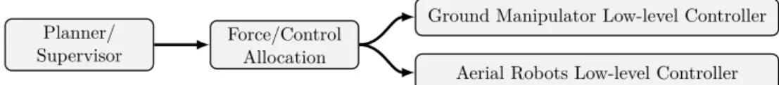
4.1 MAGMaS control overview . . . 48
4.2 MAGMaS task planner . . . 48
4.3 MAGMaS control architecture . . . 49
4.4 Force model block diagram . . . 57
4.5 Experimental underactuated AV . . . 59
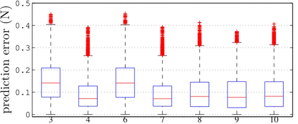
4.6 Boxplot of prediction error with MoCap data . . . 62
4.7 Force estimation model comparison . . . 63
4.8 Boxplot of prediction error with IMU data . . . 64
4.9 OTHex control block diagram . . . 67
5.1 MAGMaS simulation environment . . . 70
5.2 MAGMaS simulation tracking performance . . . 70
5.3 MAGMaS simulation joint level informations . . . 71
5.4 MAGMaS simulation AR quantities . . . 72
5.5 MAGMAS preliminary experiment, bar lifting setup . . . 73
5.6 MAGMAS preliminary experiment, manipualtor alone tracking . . . 74
5.7 MAGMAS preliminary experiment, cooperative manipulation tracking 75 5.8 MAGMaS, passive spherical joint sytem . . . 75
5.9 MAGMaS, passive spherical joint performances . . . 75
5.10 MAGMaS Componants . . . 76
5.11 MAGMaS full architecture . . . 77
5.13 OTHex aperture illustration . . . 80
5.14 Tele-MAGMaS, master side . . . 82
5.15 Tele-MAGMaS, task planner . . . 83
5.16 Tele-MAGMaS, finite state machine . . . 84
5.17 Tele-MAGMaS in action at the Hanover Fair . . . 85
5.18 MAGMaS lifting bar time-lapse . . . 87
5.19 MAGMaS bar lifting, ground manipulator wrench . . . 88
5.20 MAGMaS bar lifting, ground manipulator joint torque . . . 88
5.21 MAGMaS bar lifting, OTHex tracking . . . 89
5.22 MAGMaS bar lifting, OTHex passive joint . . . 89
6.1 PVTOL with elastic joint modeling . . . 97
6.2 Closeup on an elastic joint modeling . . . 100
6.3 Controller of a PVTOL with elastic manipulator . . . 102
6.4 Elastic actuator validation setup . . . 103
6.5 Qbmove device, model and real system . . . 105
6.6 Experimental setup for AR with elastic joint . . . 107
6.7 VSA trajectory tracking, first experiment . . . 109
6.8 VSA trajectory tracking, second experiment . . . 109
7.1 Beam flexibility modeling . . . 114
7.2 Bar tip force/moment balance . . . 116
7.3 Flexible MAGMaS modeling . . . 117
A.1 Propeller dynamic coefficient identification setup . . . 136
List of Tables
4.1 Force estimation models . . . 61
5.1 OTHex key parameters . . . 80
6.1 Experimental setup key quantities . . . 105
6.2 Experimental platform parameters . . . 108
List of Multimedia
[video 1–2015] video 1. Total Thrust Modeling and Identification with Onboard
Accelerometer and Battery. https : / / youtu . be / RdL3adVm6sA. May 2015
(cited on pages 59 and 60).
[video 2–2016] video 2. Aerial Robots with Rigid/Elastic-joint Arms:
Controlla-bility Preliminary Experiments. https://youtu.be/Gtojd5AyxtY. Oct. 2016
(cited on pages 103 and 108).
[video 3–2017] video 3. Towards Robotic MAGMaS: Multiple Aerial-Ground
Ma-nipulator Systems. https://youtu.be/ZW9M4YXLsXw. May 2017 (cited on pages 73 and 74).
[video 4–2017] video 4. Tele-MAGMaS Hanover System Presentation. https : //vimeo.com/217252361. Apr. 2017 (cited on pages 88 and 154).
[video 5–2017] video 5. Tele-MAGMaS Hanover Demonstration.
https : / / youtu . be / GRnGSvJGUKk. Apr. 2017 (cited on pages 76, 88 and 154).
[video 6–2017] video 6. Aerial-ground Cooperative Manipulation of Long Bars. https://youtu.be/TrrPEP3CNlY. July 2017 (cited on pages 87, 153 and 154).
[video 7–2018] video 7. OTHex Bar Lifting. https://youtu.be/AikN3_PgYU4. May 2018 (cited on page 81).
List of Acronyms
AM Aerial ManipulationAPhI Aerial Physical Interaction AR Aerial Robot
AV Aerial Vehicle
BLDC Brushless Direct Current CoG Center of Gravity
CoM Center of Mass DoF Degree of Freedom EE End-Effector
ESC Electronic Speed Controller FFT Fast Fourrier Transform FPV First Person View FSM Finite State Machine HMI Human-Machine Interface IMU Inertial Measurement Unit
LBR-iiwa “Leichtbauroboter”, German for lightweight robot, intelligent industrial
work assistant
LQR Linear-Quadratic Regulator
MAGMaS Multiple Aerial-Ground Manipulator System MAV Micro Aerial Vehicle
MoCap Motion Capture System NED North-East-Down
PVTOL Planar Vertical Take-off and Landing Vehicle PWM Pulse Width Modulation
ROS Robot Operating System
SQP Sequential Quadratic Programming TCP Tool Center Point
Tele-MAGMaS Human in the Loop MAGMaS UAV Unmanned Aerial Vehicle
USAR Urban Search and Rescue VSA Variable Stiffness Actuator
Part I
Chapter 1
Contribution and Overview
Contents1.1 Contributions . . . . 3 1.2 Organization . . . . 5
1.1 Contributions
Nowadays free-flying Micro Aerial Vehicle (MAV) are a mature technology which has obtained several commercial successes, e.g., crop/structure visual inspection and drone hobby racing. The next frontier for aerial robotics is symbolized by Aerial Physical Interaction (APhI), where MAV are embodied with the capability to physically interact with their environment. This opens the way to many ap-plications, e.g., contact inspection and cooperative manipulation. In recent years, many incremental contributions have been made leading to Aerial Robot (AR) de-velopment, i.e., Aerial Vehicle (AV) with the ability to physically interact with the environment. Motivated by the recent advances in the field of aerial robotics, this thesis proposes to extend the field of Aerial Manipulation (AM) by presenting the first general study of collaborative manipulation between ground manipulator(s) and aerial manipulator(s). The proposed system is called MAGMaS, which stands for Multiple Aerial-Ground Manipulator System and is based on the vision that AR can be beneficial to manipulation tasks in the form of flying companions. In particular, the motivation to combine ground and aerial manipulators resides in the desire to alleviate their respective shortcomings. This thesis showcases the first experimental demonstration of a Multiple Aerial-Ground Manipulator System (MAGMaS), opening a new route of research.
The first study on a MAGMaS is presented in [Staub–2017], which covers the modeling, control synthesis, simulation and preliminary experiments. The fact that the proposed multi-robots system is heterogeneous is carefully addressed in the control synthesis. Preliminary experiments are conducted, validating the pro-posed MAGMaS concept and the mechanical design of the AR. From this foun-dation, further work on MAGMaS is conducted, fostered by the participation to the KUKA 2017 Innovation Award1. The MAGMaS concept is enriched with a
tele-presence framework, for operation in remote or hazardous environments. The associated work, from theoretical developments to successful demonstration at the
1
https://www.kuka.com/en-de/technologies/research-and-innovation/ kuka-innovation-award/kuka-innovation-award-2017
Hanover Fair 2017, was lead by LAAS–CNRS in cooperation with INIRIA/IRISA Rennes, University of Siena and Seoul National University. The focus on the ef-forts developed during this challenge were towards integration and demonstration of a MAGMaS with tele-operation capabilities; results are detailed in [Staub–2018] and [Staub–]. In particular, I was in charge of the global architecture and integra-tion of the system, of the ground manipulator control and of the logistics. I also participated in the task planning and AR control framework developments. The last direction explored in the study of MAGMaS consisted in studying the flexibility in the manipulated load. This work was conducted in cooperation with Seoul National University and lead to an extension of the MAGMaS model by considering the flex-ibility in a co-manipulated beam. Further theoretical work was conducted in the form of a thorough system analysis and the exhibition of the flexibility properties; the corresponding results are to be found in [Yang–2018].
Based on the observation that force estimation capabilities are of paramount im-portance for APhI applications, in order to ensure both safe and stable operations. A preliminary work on external force estimation was conducted before focusing on the MAGMaS. The proposed approach relies on a class of simple models and the identification of their parameters, as presented in [Staub–2015].
Another contribution of this thesis in the field of APhI, consists in the study of elastic joints for AR. This direction of work has been explored with the main motivations of paving the way for safe APhI with the environment, thanks to the mechanical compliance induced by elastic joints. Additionally elastic joints also allow for velocity amplification, which proves useful for dynamic tasks, e.g., throw-ing. This vast topic, which is at date still almost completely unexplored in the literature, was partially addressed in [Yüksel–2016b] in cooperation with the Max Planck Institute for Biological Cybernetics in Tübingen, Germany.
Levels of Maturity of the Presented Works
The careful reader will realize that the maturity of the experimental works pre-sented is uneven. Choices have been made to maximize the research outcomes with the unavoidable limited time and resources. The MAGMaS concept presented in this work is a novel approach that needed solid theoretical foundation. Moreover, developing and conducting experiments with multi-robot systems composed of an industrial manipulator and an AR proved to be challenging and time intensive. In particular, the imposed change, during the thesis course, of industrial manipulator and AR required an extra integration work. Considering the different constraints, priority had to be given to demonstrate results, hence some directions which seemed promising in terms of research work had to be put on hold. Overall, experimen-tal work is always presented, even if in preliminary form, to validate the proposed ideas. the possible future directions for further developments on both MAGMaS and Variable Stiffness Actuator (VSA) for AR are presented in the corresponding chapters.
1.2. Organization 5
Contribution and Overview State of the Art
Modeling Estimation
and Control Results
MAGMaS: Aerial-Ground Co-manipulation
[Staub–2015] [Staub–2017] [Staub–2018] [Staub–]
Variable Stiffness
Actuators MAGMaS
Flexibility Studies
[Yüksel–2016b] [Yang–2018]
Conclusion and Future Work
Figure 1.1 – Graphical overview of the chapters, the main topics, and the relation to the publications.
1.2 Organization
An in-depth state of the art is conducted in Chapter 2, presenting the motiva-tions behind APhI in general and focusing on AM. A comprehensive review of all components needed for AM is conducted, including mechanical design, control and estimation, and the latest results in AM and cooperation between AR.
The following developments are centered around the concept of Multiple Aerial-Ground Manipulator System (MAGMaS); a totally new concept for aerial-ground cooperative manipulation developed throughout the presented work. The motiva-tions behind MAGMaS and the associated models are presented in Chapter 3. In particular, the observations leading to the concepts of MAGMaS are listed along with possible use cases. In a second part, the rigorous modeling of the MAGMaS is derived through modeling of the sub-components. An emphasis is given to the control and estimation methods in Chapter 4. Two low level control schemes for AR are discussed and the importance of force estimation is underlined. Based on these developments, an overall control architecture for MAGMaS is proposed. The MAGMaS study is concluded by the description of MAGMaS real designs and presentation of both experimental and simulation results in Chapter 5.
Lastly, two exploratory and ongoing works on flexibility are presented in the last part of this thesis. In Chapter 6, the influence and exploitation of elasticity in the AR manipulator is introduced and studied in the general AM case, accompanied with discussions on intrinsic mechanical compliance benefits for AM. A parallel pre-liminary study on the flexibility in a beam manipulated by a MAGMaS is presented in Chapter 7. A model of MAGMaS including flexibility in the beam is derived and the system properties are exhibited based on the model analysis.
Ultimately the contributions are summarized in Chapter 8. Discussions about open research directions and future possible works are presented along the results review.
Chapter 2
State of the Art in
Aerial Physical Interaction
Contents2.1 Motivations . . . . 7 2.2 Aerial Physical Interaction Paradigms . . . 10 2.3 Design of Aerial Manipulators . . . 12 2.4 Control and Estimation for Aerial Manipualtion . . . 19 2.5 Collaborative Aerial Physical Interaction . . . 23
Abstract
This chapter presents the fields of APhI and AM, the latter being a special case of the former. Sec. 2.1 outlines the motivation and the historical foundations of the APhI field, while Sec. 2.2 presents an overview of the field at large. The next two sections develop the field of AM from the mechanical design, Sec. 2.3, to the associated control theory, Sec. 2.4. The final section, Sec. 2.5, explores the thrilling topic of collaborative physical interactions for AV.
2.1 Motivations
Since August 1849 and the first use by Austrian forces of an UAV to target enemy positions. The field of UAV remained heavily fostered by military interests, from
(a) [NASA] (b) [Wikimedia Foundation] (c) [Wikimedia Foundation]
Figure 2.1 – Collections of MAV platforms: from left to right a fixed wing aircraft, an helicopter and a multi-rotor Unmanned Aerial Vehicle (UAV).
providing practice target for training, to long endurance surveillance of remote or sensible areas and combat engagement. From this military background came the name “drone” given due to the resemblance of sound of early UAV motors and the male bee. In the following developments, the emphasis is on MAV, understood as “small enough to be practical for a single-person transport and use” (see [Galinsky– 2007]), practically this maps to a weight up to 5 kg to 6 kg and a span of around 1.2 m, see Fig.B.1.
In the recent decades, due to price drops in small consumer electronics, MAV became available to the research community and industries outside heavily subsidies military projects. Leading the path to other MAV usages and designs, for both fixed-wing aircraft and rotor-crafts. In particular rescue services and agricultural industries are interested in monitoring capacities. Academia and industry, were shortly followed by the general public in the MAV market, hobbyist being focused on MAV racing and airborne photography. Seeing the success and research results for free-flight UAV operations, see [Mahony–2012] for a tutorial on multi-rotor AV, new research field on Aerial Physical Interaction (APhI) emerged in the last 15 years. The goal of this field is to provide MAV with the capability of physically interacting with the environment, ranging from simple surfaces pocking to more complex cooperative load manipulation.
Aerial Physical Interaction
Aerial Physical Interaction (APhI) is a generic term to design all physical inter-actions between one AV and its environment. A very early example can be the in-flight refueling maneuver, demonstrated as early as June 1923. As of today this procedure is still not fully automated and requires the dexterity of an aircraft pilot or a boom operator in the case of rigid boom, while the probe-and-drogue system is close to be automated, see [Wilson–2015].
The following developments are going to focus on to APhI for unmanned air-craft, whether it be for probing the environment, react to collision or manipulate objects. In order to perform APhI with MAV a few requirements are set and will be developed at length in Sec. 2.2. The first two simple tasks of APhI, that come to mind, are pocking the environment, i.e., exerting force trajectories on surfaces and perching, i.e., allowing the MAV to perch on the environment in order to recharge battery or acquire data, see Fig. B.2. Another conceptually simple APhI tasks consists in linking a MAV to the ground by mean of a tether. These tasks will be described more in depth in Sec. 2.2. The whole work of this thesis fits under the umbrella of APhI.
In Europe the research efforts towards APhI are fostered by the European Com-mission via funding of major cooperation projects. AIRobots1 from 2010 to 2013
funded under FP7 and targeted at developing a new generation of service robots, ARCAS2 from 2011 to 2015 funded under FP7 and targeted at aerial
transporta-1
http://airobots.dei.unibo.it/ 2
2.1. Motivations 9
(a) [Gioioso–2014a] (b) [Wopereis–2017a]
Figure 2.2 – Examples of Aerial Physical Interactions: (a) pocking a surface and (b) perching on a wall.
tion and assembly, AeroWorks3 targeted at enabling an Aerial Robotic worker and
Aeroarms4 from 2015 on, under H2020 fundings, which objectives are toward
vali-dation of APhI for industrial inspection and maintenance.
Aerial Manipulation
A subfield of APhI can be recognized for Aerial Manipulation (AM), being the use MAV to complete complex manipulation tasks. in the literature there is a confu-sion between transportation and manipulation, the latter being a special case of transportation including a dexterity component inherent to manipulation. In the following, transportation might be used as an illustration of basic manipulation capabilities. As such, AM regroups all the tasks where an object has to be trans-ported or manipulated by one or a group of MAV, see Fig. B.4. In order to do so, developments in mechanical design of Aerial Manipulators, control and estimation techniques and collaboration framework are necessary. Mechanical design for AV are explored in Sec. 2.3, both for APhI and AM, with a special focus on some uncon-ventional designs. Usually, these designs coupled with the physical interaction rise new problems for the control of the AV, presented in Sec. 2.4. Going even further in complexity, there is the realization of collaborative APhI tasks, like cooperative manipulation with other AR, Humans or Ground Robots, this topics is surveyed in Sec. 2.5. The work of this thesis is oriented towards AM paradigms.
Perception
Finally while perception of the environment is of paramount importance for the realization of autonomous APhI tasks, it is not the scope of the works presented in this thesis, as it covers a very wide and active area of research in itself. In particular in the followings the perception problem to acquire UAV state are always considered as solved in order to focus on the control theory aspects.
3
https://www.aeroworks2020.eu/ 4
(a) [Nguyen–2015] (b) [Mellinger–2010]
Figure 2.3 – Examples of Aerial Manipulation: (a) drawer opening/closing and (b) collaborative load transportation.
2.2 Aerial Physical Interaction Paradigms
In this section, a review of the principal challenges faced and applications of APhI is presented. An overview of APhI designs, with special emphasis on ‘un-conventional’ AV solutions is proposed. The main applications of APhI are detailed and discussed, including perching, force exertion on surfaces and tethered AV.
2.2.1 Original Mechanical Designs
Typical off-the-shelf MAV are not mechanically fit for APhI tasks, often the pro-pellers volume is open to collision and they don’t have specific termination for contact with the environment. Therefor to pave the way to APhI and AM the first modification of standard MAV concerns mechanical design to enable APhI capaci-ties. An in-depth review of the different mechanical design for Aerial Manipulator is presented in Sec. 2.3, the taxonomy presented there also applies for the simplest APhI tasks. For sake of completeness some mechanical designs only fit for APhI that does not involve manipulation are presented here, with a selection depicted in Fig 2.4.
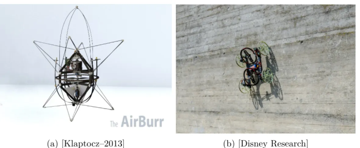
A primary target of APhI mechanical design is to protect the propeller vol-ume from intrusions and alleviate collision contact disturbances w.r.t. the flying behavior. One approach proposed by [Briod–2014] is to mount to passive rotating spherical shell around the main frame of a classical Vertical Landing and Take-Off Vehicle (VTOL), this mechanism enables the UAV to collide with obstacles without compromising its flight stability. This design allows to bounce on the envi-ronment, a refinement is presented in [Salaan–2017] using hemispherical shells, thus leaving an aperture for an End-Effector (EE) to reach outside of the shell. Lately this approach of shelling MAV in spherical structure was developed for package delivery in [Kornatowski–2017]. Another AV concept, the AIrBurr, is presented in [Klaptocz–2013] and [Briod–2013], the emphasis is on proposing a design signifi-cantly reducing the effect on impacts with the environment on the flying behavior, ultimately providing a recovery procedure if the system falls on the ground. This
2.2. Aerial Physical Interaction Paradigms 11
(a) [Klaptocz–2013] (b) [Disney Research]
Figure 2.4 – Two Original Designs: (a) the AIrBurr capable of falling to the ground without breaking and upright itself to take-off again, and (b) the Vertigo capable of climbing walls.
allows ‘blind’ exploration of cluttered environments. Some research are exploring the possibility to climb wall, as in [Pope–2017] where a standard quadrotor is aug-mented with a kind of locomotion mechanism for vertical walls. Or this project, Vertigo5, with a cart like vehicle actuated by two orientable propellers, even though
this one is not an AV it represents and interesting use of propeller actuation. Other systems are developed for custom applications, like the large quadrotor presented in [Tsukagoshi–2015], fitted with a door handle opening mechanism and using the propellers to push door open. Or the quadrotor, in [Molina–2017], fitted with a sawing mechanism for perching and cutting tree branches near power lines.
2.2.2 Applications
The applications of APhI, not embraced by AM, consist of perching, when a MAV attaches itself temporarily to the environment, or force exertion on a surface, by pushing on a point or sliding while pushing. Collision recovery is not detailed, even though collisions are physical interactions, because the recovery happens when there is no more physical interaction, i.e., in free flight.
Perching
Perching is investigated in the field of APhI, as a mean to increase the endurance of MAV. Indeed once perched and fastened the MAV do not need to resist gravity with their propellers, hence reducing their power consumption. Perching can be useful for sensor network, being temperature sensor or cameras used for environment monitoring, e.g., for crowd monitoring, or working as radio relays in post-disaster environment. Another usage of the perching maneuver is solar battery recharging,
5
a MAV with low battery terminal voltage can perch and use solar panel to re-charge its battery before continuing the mission. In [Wopereis–2017a] the authors investigate perching for multi-rotor AV, they proposed an associated design for perching on vertical walls. The results presented in [Pope–2017] go even further and propose a solution to perch and climb on vertical surfaces. In [Thomas–2016b] aggressive flight maneuver for perching on inclined surface is investigated. Perching capabilities have also been successfully demonstrated for fixed-wing MAV, i.e., small airplanes, as in [Mehanovic–2017] and [Desbiens–2011].
Force Exertion on Surface
Another often described task in the literature of APhI is the exertion of forces on a surface while following a force trajectory. This description translates to pock-ing/pushing were the goal is to exert a desired force on some location, either for sensing with contact sensor or trigger mechanism, e.g., switches, and to sliding along a surface while maintaining contact, e.g., for ceiling painting. Examples can be found in [Gioioso–2014a] with a near-hovering controller used to exert 3D forces on a vertical surface via a passive tool-tip, in [Ryll–2017] a multi-directional thrust AV is used for pipe contact inspection, applying forces on the measurements points, in [Yüksel–2017] where a rigid tool is used to slide on an uneven ceiling or in [Alexis–2013] for pushing along a vertical surface with feedback from pressure sensor. Another interesting design is proposed in [Papachristos–2014a], focusing on exerting a large force on the surface by re-orienting the propellers. Another approach, proposed in [Wopereis–2017b], for applying contact forces on the envi-ronment that are comparable to the MAV’s weight relies on LQR control to achieve substantial force application on a specific contact point.
Tethered Aerial Vehicle
The last APhI task reviewed consists of linking an AV to the ground by mean of a cable. They can be used to transport energy or data increasing the AV autonomy, see Fig. B.3. Moreover the tether can be used to enhance the flight performances, as in [Sandino–2014a], for hovering, or to guide the landing, as in [Sandino–2014b]. And even to perform maneuvers impossible without the tether, like smooth and safe landing on a sloped surface as in [Tognon–2016b]. Tethered AV are now available as a product in France6, with application to area surveillance with visual sensor or
air quality monitoring.
2.3 Design of Aerial Manipulators
In this section an exhaustive taxonomy of aerial manipulator designs is conducted. The designs proposed in the literature can be ordered considering three main
cri-6
2.3. Design of Aerial Manipulators 13
(a) [Elistair] (b) [Kondak–2009] (c) [Tognon–2016b]
Figure 2.5 – Tethered Aerial Physical Interaction: (a) commercial solution for en-during monitoring, (b) collaborative load transportation and (c) exploitation of tether to land on a sloped surface.
teria: i) the flying platform design, ii) the manipulation mechanism and iii) the prehension mechanism. Each of them being developed hereafter.
2.3.1 Flying Platform Designs
In both APhI and AM, the AV design is of paramount importance. Indeed the design of the AV bears underlaying system properties that facilitate or inhibit the APhI tasks. By mean of control certain properties can be smartly leveraged but it is often easier to start with an adequate mechanical design. Here are regrouped the main design ideas present in the vast literature of APhI.
Under-actuated Design
Among the different aerial manipulator systems present in the literature a vast majority can be grouped by their under-actuation characteristic. That means that their translational and rotational dynamics are not fully decoupled, i.e., they can not follow an arbitrary 6D trajectory in SE(3). The under-actuation property arises from the mechanical design of the platforms, where the propeller(s) are physically arranged so that the total thrust is always exerted along one direction in the body frame of the AV, typically along the z-axis, thus lateral motion of the AV requires some tilting of the whole body to re-orient the total thrust in the desired direction of motion.
Collinear propellers: a design in which all propeller rotation plane are
co-planar. This is the case for the most well know MAV platform, the planar quadrotor, which consist of four propellers distributed along the edge of a rectangle (regular or not), all oriented in the same direction. The simplicity of the mechanical design comes at the cost of under-actuation. Its simplicity and robustness also made it famous among hobbyists. Rotational motion is achieved via differential commands
of the propellers. One can group in the same family hexa- and octo-rotors, follow-ing the same propeller layout rule but with regular hexagon and octagon patterns, respectively. The benefit of such a design is usually an increase of payload which proves to be capital for heavy load transportation. This multiplication of propellers does not result in a one to one increase of the payload has it usually also results in a power consumption increase which needs to be balanced by additional battery. Overall the design is still beneficial and is used to carry heavy loads, e.g., dual arm manipulator of 1.8 kg, as in [Suarez–2017a], or sensors in non-AM scenarios like the ALTA8 from Free Fly Systems7 capable of lifting a 9.1 kg payload for an empty
weight of 6.2 kg. The general model of multi-rotor MAV is developed in depth in Sec. 3.2, with emphasis on the collinear case, and a possible control strategy for APhI is detailed in Sec. 4.2.
Ducted-fan: a design in which propeller are encased in a duct. The principle of
this design is, as its name suggests, that the airflow is produced by two propellers encased in a duct, i.e., a small pipe, they are counter rotating to allow yaw control. Rotational motion is achieved via actuated flaps in the airflow. The main advan-tage of this design is the inherent safety from already encased propellers, which is paramount for interaction with human users. Also the ducted fan design exploits aerodynamics properties to increase the lift produced by propellers by guiding the airflow in the duct. One application is presented in [Fumagalli–2014].
Helicopter: a design in which a main propeller produces the actuation thrust
while a smaller one acts as a stabilizer. This design is well know and also suited for big AV as produced by aircraft industries. An example of large helicopter with industrial manipulator can be found in [Kondak–2014]. While research on AM are also conducted with smaller helicopter as in [Pounds–2014].
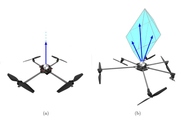
Multi-directional Thrust Design
A recent trend in the aerial manipulator design is the emergence of multi-directionnal thrust AV, meaning that their total thrust can be oriented in several directions in the body frame. This allows for their translational and rotational dynamics to be fully decoupled (up to the actuation limits), i.e., they are fully actuated. To guarantee the full actuation the mechanical design imposes non-collinear layout of the propellers. Due to that, full actuation comes at a cost of internal force, i.e., loss of energy efficiency. One can choose to start from a well known under actu-ated structure and modify it, like the work present in [Rajappa–2015][Ryll–2017] on hexarotors. A similar idea is proposed for quadrotor in [Odelga–2016], based on a parallelogram principle to reorient the propellers. Or one can even think about designs encompassing more novelty, aimed at automatically optimize the full actu-ation, as the design described in [Park–2016] or aimed at allowing the exertion of
7
2.3. Design of Aerial Manipulators 15
given wrenches applied by the EE via automated design in [Nikou–2015]. A judi-cious choice in the layout leads to a multi-directional platform, while keeping the control input allocation simple and minimizing the internal forces. These platforms can follow an arbitrary trajectories in SE(3). But more importantly as lateral force exertion do not require any orientation change, they can withstand external force perturbations while following 6D trajectories. Another work in this direction is presented in [Brescianini–2016], where an eight-rotor configuration that maximizes the vehicle’s agility in any direction is derived based on a static force and torque analysis for generic actuator configurations.
Mixed Design
Interestingly, some design try to exploit the advantages of both under- and full ac-tuation, refereed to as mixed design hereafter. It is the case of the design presented in [Ryll–2016] where the platform can change in flight the propeller orientation, allowing power efficient free-flight and perturbation resistant physical interaction. This versatility comes at the cost of mechanical complexity and let the need of extra-actuation (to tilt the propeller) arise. Similar solution is proposed by the Voliro8
project with one tilting motor for each propeller, allowing more flexibility in global configuration. Another more basic solution consist in taking an under-actuated quadrotor and add a propeller with spinning axis in the direction of the force ex-ertion, as in [Albers–2010] or [McArthur–2017]. With this additional propeller the system gains some actuation degree but remains under-actuated. Some design just use quadrotors as orientable thrust generator fixed on a structure, e.g., [Nguyen– 2015] with three quadrotors attached via passive rotational joints on a triangular structure holding a gripper or a tool.
Fixed Wing Design
Fixed wing design are purposely omitted in this taxonomy as there inherent flight behavior is not fit for AM. From the APhI point of view this design can be used in perching, as reviewed in Sec. 2.2.2.
2.3.2 Embedded Manipulation Mechansim Designs
In order to pass from APhI to AM, a manipulator or at least a prehension mechanism needs to be embedded on AV. With this extension AV can be properly called Aerial Robot (AR). In the literature, several different design approaches for manipulator were identified, see Fig. B.5. The main idea remaining that a manipulator increases the dexterity of the AR for manipulation tasks, eventually compensating for under-actuated AV.
8
(a) [Kondak–2014] (b) [Suarez–2017a] (c) [Danko–2015] Figure 2.6 – Different kind of aerial manipulators: (a) industrial 7-DoFs, (b) dual arm manipulator and (c) parallel manipulator mounted below a MAV.
Joint-Actuated Manipulator
The simplest approach consist in taking off-the-shelf serial manipulator solutions and attached them below a AV . This as been proposed with top grade industrial ma-nipulators in [Kondak–2014]. But also with smaller lightweight manipulator based on classical design as in [JimenezCano–2013]. As the manipulator is mounted on the AV, there exists a strong mechanical coupling between their respective dynam-ics, usually compensated by means of control. An interesting approach concerning this is proposed in [Ruggiero–2015], where moving the battery as a counterweight is experimented. In general, the solution of bluntly strapping two pre-existing systems together does not provide good performances as the manipulator workspace is sig-nificantly reduced by the AV actuation limits and the flying performances degrade due to the strong coupling.
Deported Actuation Manipulator
A way to reduce the dynamical coupling is to reduce the inertia of the manipulator, typically by using cable or transmission-belt mechanism. With this kind of mech-anism the motors moving the joints can all be located close to the AV platform and its center of mass (CoM). Thus reducing the dynamical coupling as the norm of the inertia tensor of the manipulator remains small. An example can be found in [Tognon–2017].
Parallel Manipulator
Another kind of manipulator design for AM, is the parallel design which allows dexterous manipulation. In [Keemink–2012] a delta design mixing actuated and passive DoF is used to propose a robust and lightweight aerial manipulator, which as been enhanced in [Fumagalli–2016]. The parallel design is also used in [Steich–2016] in order to inspect tree cavities and a full-body controller is presented in [Kamel– 2016]. Finally [Danko–2015] present a large parallel manipulator design mounted below a quadrotor, in order to compensate for MAV motion during pickup.
2.3. Design of Aerial Manipulators 17
Another parallel manipulator design is presented in [Six–2017], where instead of embedding a parallel manipulator on a MAV, quadrotors are used as actuators of a parallel manipulator, i.e., their are linked by a rigid articulated passive chain, and their respective motion induce displacement of the EE.
Passive Manipulator
For certain constrained manipulation tasks, or when multi-directional thrust plat-form are used, an active manipulator might not be necessary. This means that the actuated Degrees of Freedom (DoF) of the aerial manipulator are already matching the DoFs of the tasks: this is the main idea behind the use of passive joint manip-ulator. The passive joint can also be seen as a way to decouple the behavior of the manipulator EE and the flying platform. For example a full 3D passive revolute joint allows to decouple the rotational dynamics of the EE and the AV , this proves useful if the rotation actuation capacity of the AV are small as in [Nguyen–2015].
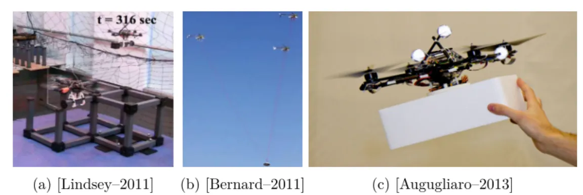
Cables Links are a special case of passive manipulators: in the sense that,
when the cable is taut, they can be thought as a one link manipulator attached via a passive joint to the AV. AM accomplished by a group of AR taut to a plat-form is presented in [Manubens–2013]. Experimental results with helicopters were presented in depth in [Kondak–2009] and [Bernard–2011].
Compliant Manipulator
Compliant manipulators have made a recent apparition in AM field and are com-posed of joints that are actuated but with an additional capacity to be elastic around their setpoint. This is often achieved through the use of elastic components in the design of the manipulator, e.g., springs, as in [Yüksel–2015] and [Suarez– 2015a] [Suarez–2015b] [Suarez–2016] [Suarez–2017b]. The main motivation is to ensure soft collisions with the environment, thus preventing the AR to become un-stable on collision, see [Bartelds–2016] for direct impact experiments. The addition of elastic behavior in the manipulator increases significantly the complexity of the mechanism and the associated control algorithms.
Multiple Arms Manipulator
Another manipulator structure which needs to be mentioned in this taxonomy is the multiple arms manipulator, where the manipulator appendage is consti-tuted of several arms. The first successful description and validation can be found in [Suarez–2015a] [Suarez–2017b]. These demonstrations were followed by a human operated commercial products9 by another organization. A recent work, [Orsag–
2017], presents a detailed analysis of the coupling between dual-arm AR and the environment during manipulation, proposing to focus on three different coupling descriptions (momentary-loose-strong) to benchmark performances. Another ap-proach found is the literature, see [Yeol–2014], aims at having three tentacle-like
9
(a) [Gawel–2017] (b) [Kessens–2016] (c) [Mohammadi–2016] Figure 2.7 – Different prehensors for AM: (a) magnetic mechanism to grasp non flat ferrous objects, (b) vacuum based prehensor working with an airborne pump and (c) swarm grasping of a cylindrical object.
mechanism below an AR to grasp an object or perch on the environment, also en-abling the system with locomotion capabilities. This mechanism is a bridge between a manipulator and a prehensor.
No manipulator
One approach to circumvent the use of embedded manipulators and their drawbacks, or when manipulators DoFs are not needed to conduct the task, is to attach a prehension mechanism or a dedicated tool rigidly to the AV, either directly on it or on a rigid arm. This approach as been investigated in [Ryll–2017] with for tools and in [Lindsey–2011] for grippers. Another approach proposed recently, in [Zhao– 2017], is to have an AV re-configurable geometry, allowing to encircle the load by a ring of propellers. More details on the prehension mechanisms are to be given in the next section.
2.3.3 Prehension Mechanism Designs
To complete this aerial manipulator design section, a review of the main prehension mechanisms used in the field of AM is introduced, see Fig. B.6 for some examples.
Mechanical Claws
This is the standard gripper mechanism of robotics, composed of two (or more) claws or fingers actuated by one (or more) electrical motor located in the gripper. The motion can either be linear or rotational, e.g., [Thomas–2016a][Backus–2014]. The grasping is realized by encircling part or all of the object to be manipulated. This kind of design are standard and quite robust, hence their use. Their main advantage is their compactness and versatility coupled with their weight/grasping force ratio. Moreover as the actuator are electrical there is no need for power conversion, i.e., they can be plugged directly on the battery.
2.4. Control and Estimation for Aerial Manipualtion 19 Vacuum Based Prehensor
Another way to attach to an object or surface is to use vacuum based mechanisms. They can be passive mechanism composed of suction cup, like the one proposed in [Wopereis–2017a]. The main advantage being their light weight, while the suction force can not be controlled and suction on surface is not guaranteed. Moreover an additional mechanism for releasing is necessary. An effort to overcome the latest two drawbacks can be seen in the design of a vacuum pump based gripper in [Kessens– 2016], sticking/unsticking consist then in switching on/off the pump. Thanks to careful design, the weight from the pump is minimized, making AM practical. In a recent work on blimp like10 AR the grasping system is also based on difference of
pressure to realize suction.
Magnetic Prehensor
For completeness magnetic prehension is introduced. Obviously this approach only works on ferrous objects, or objects previously equipped with ferrous receptors. As for the vacuum case one can use passive magnets, which consume no energy but necessitate high force exertion to release the object. Electro-magnet can be used to circumvent this issue, their power consumption remaining modest. This has been proposed in [Gawel–2017] or for a simpler design [Bähnemann–2017]. The use of magnetic prehensor has been fostered by the 2017 MBZIRC Challenge11
requirements to pick objects with ferrous surface.
MAV Swarm Prehension
An interesting approach to reduce the design complexity of the AR is to use a swarm or a group of them to grasp and object, ensuring firm grasp by multiples simple contacts. This approach is studied in [Gioioso–2014b] and [Mohammadi–2016], where the authors use MAV to mimic the behavior of fingers and coin their solution as “flying hand”. Another, lately emerging design as been proposed in [Zhao–2017] where the geometry of the AV can be re-arranged in flight, giving the possibility to surround objects.
2.4 Control and Estimation Techniques
for Aerial Manipulator
From control point of view, APhI is way more challenging and demanding than free flight. Not only geometric pose controllers are needed to allow the AV to track de-sired pose trajectories, but also force based controllers to ensure intrinsically stable behavior while in contact with the environment. In order to allow feedback force
10
https://www.festo.com/group/en/cms/11957.htm 11
control, measurements or estimation of the external forces are necessary. Finally tele-operation frameworks used in case of human supervision are briefly introduced. 2.4.1 Geometric Pose Control
Geometric control of AVs aims at stabilizing the system in free flight and allowing trajectory tracking. The pose of the AV is expressed by a position in R3 and a
3-DoF rotation, thus the pose is in the Special Euclidean group SE(3). In the liter-ature several different orientation representation are present, Euler angles which are prone to Gimbal Lock, see [Mistler–2001][Spedicato–2016], quaternion which have a redundant representation of SO(3), see [Mayhew–2011] and rotation matrix which do not suffer the two previous drawbacks but are a non-compact representation, see [Lee–2010]. The first approach encounter in the literature consists in applying classical synthesis techniques to an approximate linear model of the vehicle dynam-ics. In [Castillo–2005], the linear controller sequentially stabilize the thrust and then the orientations, this sequential approach is also used in [Spedicato–2016].
The call for increasing performances and maneuverability led to the use nonlin-ear control strategies. They rely on dynamical feedback linnonlin-earization, see [Mistler– 2001], to bring the system in a linear form where linear control techniques can be applied. In [Raffo–2010] an approach based on model predictive control and H∞
controller is proposed as nonlinear robust control strategy. A popular nonlinear tracking controller is developed on the special Euclidean group SE(3) in [Lee– 2010], with almost global stability. Note that non-linear control approaches are typically more computationally intensive, which might be an issue for embedded deployment. But nowadays small computers, e.g., intel NUC series12, are powerful
enough to run model predictive control algorithm and some additional optimization problem in real-time, see e.g., [Baca–2016].
2.4.2 Force Based Control
To perform safe APhI, trajectory tracking control is not sufficient and additional control strategies addressing the force interaction are necessary. Indeed in such applications, a flying robot is required to exert certain forces and torques to the environment, while maintaining a stable flight. A classic techniques rely on admit-tance/impedance framework as in [Augugliaro–2013] for admittance and [Lippiello– 2012] [Gioioso–2014a] [Ruggiero–2014] for impedance. Other approaches relies on energetic considerations. For example in [Mersha–2011] relying on port-Hamiltonian modeling and bond graphs. Or [Yüksel–2014b] relying on an Interconnection and Damping Assignment Passivity Based Control (IDA–PBC) scheme.
2.4.3 External Forces Estimation
The subject of external forces estimation is of paramount importance for MAV as this information is useful to improve flight behavior (reaction to wind and/or
12
2.4. Control and Estimation for Aerial Manipualtion 21
collision) and to allow quality APhI with force feedback. Hereafter the term external forces is used to refer to 6D general forces or 6D wrench indifferently.
Necessity of Force Estimation
The reason to privilege estimation of external forces over actual sensor measure-ments, despite the better quality of the measuremeasure-ments, mainly comes from the issue to integrate force sensors and their associated electronics on MAV. Indeed, despite the recent years advances in 6D Force/Torque sensors (F/T-sensor) miniaturiza-tion of the associated electronics usually suffer from poor form-factor and weight unsuitable for MAV applications, meaning that at the same time the volume of the electronics and its weight make the sensor solution unusable in practice. The weight is especially an issue as, at the same time, it reduces the flight endurance and the exploitable actuation bandwidth for the APhI tasks. Even though, an interesting development in miniaturized 6D F/T-sensor is the mini sensor13, with fitting
elec-tronics, specially designed at IIT to fit the iCub robot. The power consumption of such a device can also be an issue, as it would drain the battery and hence re-duce the flight endurance of the overall system. Finally a strong argument against F/T-sensor is the fact the measurements are localized, e.g., [Alexis–2013], hence the external force information only describes what happens at the measurement points, whereas the estimation approach provide information on force applied in any point of the structures. Another drawback of F/T-sensor is their cost, which often amount for as much as the rest of the MAV if not more, compared to the ever decreasing cost of embedded computing driven by the cellphone market.
To overcome these drawbacks force estimation is used. The force estimation methods also come with limitations, the main one being the aggregation of a lots of phenomena in the same estimate. Namely all wrenches applied on the AR are combined like contact(s) with the environment and wind, on top of that model in-accuracy and raw measurements bias and noise are merged in the estimate. Thank-fully these effects can be mitigated through calibration of the the different sensors and parameter identification routine for the model(s) used. The addition of contact detection mechanisms, as in [Rajappa–2017], allows to separate the contribution from physical interaction and wind.
Flight Behavior Improvements
External force estimation can be beneficial to free-flight MAV, especially outdoor where the wind, an external force, is often neglected in the control synthesis. Indeed by taking the wind into account the flight performances can be signifi-cantly improved for MAV [Alexis–2010], other schemes to do so have been proposed in [Tomić–2016] (and previous) and [Rodriguez–2016][Rodriguez Salazar–2017] for gliders. Inside operations are not exempted from wind effects, as the airflow pro-duced by the propeller generates aerodynamic perturbations which can be related
13
to wind. More toward APhI, external force estimation can be used to detect colli-sion with the environment, as in [Tomić–2015] and trigger recovery procedure. This can prove extremely useful in cluttered and unstructured environments, finding its application in unknown or damaged buildings exploration.
Physical Interactions
In order to perform APhI the force based control strategies detailed in Sec. B.1.6 require a force feedback. Making the force estimation component mandatory for their implementation. In [Ruggiero–2014] a momentum based external generalized force observer is presented, which requires to measure the whole dynamical system state, the control torques and the thrust to produce an estimate of the external wrench. The methods has been proven to work indoor by using a precise off-board motion capture tracking. In [Augugliaro–2013] a classical Unscented Kalman Fil-ter is presented to estimate the exFil-ternal force and torque acting on a quadrotor. This approach has also been tested with the use of an off-board motion capture system. An external wrench estimation based on momentum-based observer was used in [Ryll–2017] to demonstrate force exertion by a multi-directional thrust AV. Another approach is described, in [Yüksel–2014a] with a Lyapunov based nonlinear observer. Another estimation scheme based on the system dynamic model is pro-posed in [Tomić–2014]. In [Rajappa–2017] the external wrench estimation is based on a residual estimator.
A static mapping between commanded thrust and actual force has been pro-posed by [Bellens–2012]. A more accurate, yet static, mapping of the force produced by a typical brushless motor for AV has been proposed by [Spica–2013], based on discretized force measurements for desired commands.
2.4.4 Tele-operation Framework
Tele-operation refers to control frameworks in which remote human operators are supervising systems of various autonomy levels, often providing high level control thanks to their reasoning abilities or manually driving robots, hence the operator side is referred as master and the remote robotic system as slave, see [Niemeyer– 2008] and [Passenberg–2010]. In order to provide the human operator with situa-tional awareness about the system and its surroundings tele-presence paradigm are used, employing either visual feedback or haptic feedback.
Visual feedback is conceptually simple, a camera (or several) is placed in the slave side, to provide the master side with a view of the environment and robotic system. Haptic feedback consists in providing the master side with force or po-sition/velocity feedback from the slave side and are detailed hereafter. Haptic feedback associated with tele-operation is named bilateral tele-operation and is provided via an haptic device which is a robot. The typical commands for both master and slave robotics systems are force and position/velocity ones. A bilateral tele-operation framework is described by its number of channels, i.e., the number of
2.5. Collaborative Aerial Physical Interaction 23
commands exchanged between the master and slave. For example if the slave robot receives a single type of command and the master side receive only one type of feed-back, the architecture is named 2-channel bilateral tele-operation. In [Son–2013] the human operator’s performances, in terms of maneuverability and perceptual sensitivity, through bilateral tele-operation for multiple robots are investigated. In particular, force cues are used to transcribe the proximity of obstacles in the remote environment and velocity cues to transcribe the velocity mismatch of the robots.
Based on the type of commands accepted by the slave robots and the kind of commands accepted by the master, impedance and admittance framework are used. All combination of commands type for the master and slave side are possible and there is no a priori best choice, combination shall be tested and evaluated based on robustness (w.r.t. communication, model uncertainty, external disturbances, ...), task performance, tele-presence (as felt by the operator) and transparency (dynamic cancellation of master and slave systems). Evaluation of the impact of different haptic cues on UAV operators can be found in [Son–2013]. Comparison of transparency as defined by control theory and felt by user is investigated in [Hirche– 2012].
There are two additional ways of using tele-operation from and high level control perspective. Haptic cues can be used to render virtual fixtures or virtual fences to the operator, the former helping guiding some task relevant motions and the later shielding some area of the environment, e.g., to avoid collision. Also the tele-operation can be used in a shared control paradigm, where the slave system autonomously carries out a task, and the master is used to generate local trajectory modifications. Either spatial, i.e., altering the trajectory to avoid and obstacle, or temporal, i.e., slowing down the motion to reduce dynamical efforts. These two kind of modifications allow the operator to provide update on the system or the environment without triggering re-planning.
2.5 Collaborative Aerial Physical Interaction
From a semantic stand point, collaboration (working jointly with other toward a common goal) and cooperation (operating together to realize a task) are considered equivalent. A collaboration denotes a joint work, it does not necessary involve physical interaction, with the environment or with the other collaborators, that is to say heterogeneous robots, ground and AV, mapping/monitoring an area is a collaboration task but not relevant in the scope of APhI.
Collaboration between Aerial Vehicles
A few works considering swarm, or team of AR, performing APhI with the environ-ment or inside the swarm have been presented, see Fig. 2.8. Most notably, swarm of AR are used for collaborative construction, as in [Augugliaro–2014], to build a tower structure out of bricks or to build tensile structures, e.g., bridge, as in [Augugliaro– 2015], or to assemble cubic structure in [Lindsey–2011] or more complex structure