Applicability of Composite Sway Structures to Sway Frames
118
0
0
Texte intégral
(2)
(3) Acknowledgements Professor J.P. Jaspart, promoter of this work, is gratefully acknowledged for having supervised this work and for his helpful advices. I am also grateful to my colleagues and to the European partners of the ECSC project “Applicability of composite structures to sway frames” who have participated, in a way or another, to the elaboration of the present work. Finally, I would like to thank my family and particularly my wife for their support. Jean-François Demonceau.
(4) Table of contents ABSTRACT NOTATIONS. CHAPTER 1 1.1 1.2. : INTRODUCTION................................................................................................ 1-1. CONTEXT .............................................................................................................................. 1-1 OBJECTIVES AND RESEARCH STEPS ...................................................................................... 1-2. CHAPTER 2 FRAMES. : STATE-OF-THE-ART KNOWLEDGE ON COMPOSITE SWAY BUILDING .................................................................................................................................. 2-1. 2.1 INTRODUCTION ..................................................................................................................... 2-1 2.2 SWAY EFFECTS IN STEEL BUILDING FRAMES ........................................................................ 2-1 2.2.1 Introduction ......................................................................................................2-1 2.2.2 Frame idealisation ...........................................................................................2-2 2.2.3 Member cross section classification ................................................................2-4 2.2.4 Frame classification .........................................................................................2-5 2.2.4.1 Braced and unbraced ................................................................................................ 2-5 2.2.4.2 Sway and non-sway.................................................................................................. 2-6 2.2.4.3 Summary .................................................................................................................. 2-8 2.2.5 Types of structural analyses and associated verifications ...............................2-8 2.2.5.1 Introduction .............................................................................................................. 2-8 2.2.5.2 First-order elastic analysis...................................................................................... 2-10 2.2.5.3 Critical elastic analysis ........................................................................................... 2-10 2.2.5.4 Second-order elastic analysis ................................................................................. 2-10 2.2.5.5 First-order rigid-plastic analysis............................................................................. 2-11 2.2.5.6 Second-order rigid-plastic analysis ........................................................................ 2-11 2.2.5.7 Non-linear analysis................................................................................................. 2-12 2.2.5.8 Overview of the considered frame analyses ........................................................... 2-12 2.2.6 Simplified analytical methods for steel sway frames .....................................2-13 2.2.6.1 Introduction ............................................................................................................ 2-13 2.2.6.2 Amplified sway moment method ........................................................................... 2-13 2.2.6.3 Sway-mode buckling length method ...................................................................... 2-14 2.2.6.4 Merchant-Rankine approach .................................................................................. 2-15 2.2.6.5 Simplified second-order plastic analysis ................................................................ 2-16 2.2.6.6 Wind moment method ............................................................................................ 2-17 2.2.7 Conclusions ...................................................................................................2-18 2.3 COMPOSITE STRUCTURES ................................................................................................... 2-18 2.3.1 Introduction ....................................................................................................2-18 2.3.2 Composite slabs ............................................................................................2-19 2.3.3 Composite beams..........................................................................................2-20 2.3.4 Composite columns .......................................................................................2-22 2.3.5 Composite joints ............................................................................................2-24 2.3.5.1 Introduction ............................................................................................................ 2-24 2.3.5.2 Joint characterisation .............................................................................................. 2-25 2.3.5.3 Joint classification .................................................................................................. 2-28.
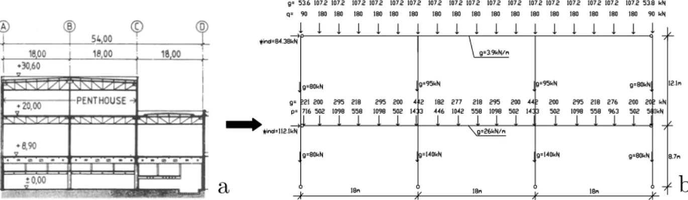
(5) 2.3.5.4 Joint modelling and idealisation ............................................................................. 2-29 2.3.6 Conclusions ...................................................................................................2-32 2.4 CHAPTER CONCLUSIONS ..................................................................................................... 2-32. CHAPTER 3 3.1 3.2 3.3 3.4 3.5 3.6 3.7. : STUDIED BUILDINGS....................................................................................... 3-1. INTRODUCTION ..................................................................................................................... 3-1 “ISPRA” BUILDING ................................................................................................................ 3-1 “BOCHUM” BUILDING ........................................................................................................... 3-3 “U.K.” BUILDING .................................................................................................................. 3-5 “EISENACH” BUILDING ......................................................................................................... 3-5 “LUXEMBOURG” BUILDING .................................................................................................. 3-6 CHAPTER CONCLUSIONS ....................................................................................................... 3-7. CHAPTER 4 : TOOLS FOR THE EVALUATION OF THE RESPONSE OF STRUCTURAL ELEMENTS IN COMPOSITE BUILDING (ACCORDING TO EC4)........................................ 4-1 4.1 4.2 4.3 4.4 4.5. INTRODUCTION ..................................................................................................................... 4-1 “BEAM-TO-COLUMN COMPOSITE JOINT” SOFTWARE ............................................................ 4-1 “COMPOSITE BEAM” SOFTWARE ........................................................................................... 4-3 “PARTIALLY ENCASED COMPOSITE COLUMN” SOFTWARE ................................................... 4-3 CONCLUSIONS....................................................................................................................... 4-4. CHAPTER 5. : NUMERICAL MODELLING ............................................................................ 5-1. 5.1 INTRODUCTION ..................................................................................................................... 5-1 5.2 NUMERICAL TOOL AND MODELLING ASSUMPTIONS ............................................................. 5-1 5.2.1 Introduction ......................................................................................................5-1 5.2.2 Presentation of the numerical tool ...................................................................5-1 5.2.3 Assumptions relative to the modelling of the structures ..................................5-2 5.2.3.1 Introduction .............................................................................................................. 5-2 5.2.3.2 Modelling of the materials........................................................................................ 5-2 5.2.3.3 Modelling of the constitutive members and joints ................................................... 5-3 5.2.4 Assumptions relative to the performed analysis ..............................................5-4 5.2.4.1 Introduction .............................................................................................................. 5-4 5.2.4.2 Critical elastic analysis ............................................................................................. 5-5 5.2.4.3 First-order rigid-plastic analysis............................................................................... 5-5 5.2.4.4 Non-linear analysis................................................................................................... 5-6 5.2.5 Load combinations...........................................................................................5-6 5.2.6 Conclusions .....................................................................................................5-7 5.3 BENCHMARK STUDY ............................................................................................................. 5-7 5.3.1 Introduction ......................................................................................................5-7 5.3.2 Main differences in the modelling assumptions adopted by the partners ........5-8 5.3.3 Analysis of the results....................................................................................5-10 5.3.3.1 Ultimate load factors .............................................................................................. 5-10 5.3.3.2 Displacements in the frames................................................................................... 5-10 5.3.3.3 Bending moment diagrams..................................................................................... 5-11 5.3.4 Reasons explaining the result differences .....................................................5-11 5.3.4.1 Differences between the simulation results ............................................................ 5-11 5.3.4.2 Differences between the simulations and the test results ....................................... 5-11 5.3.5 Conclusions ...................................................................................................5-13 5.4 APPLICATION TO REFERENCE FRAMES................................................................................ 5-14 5.4.1 Introduction ....................................................................................................5-14 5.4.2 “Ispra” building ...............................................................................................5-14.
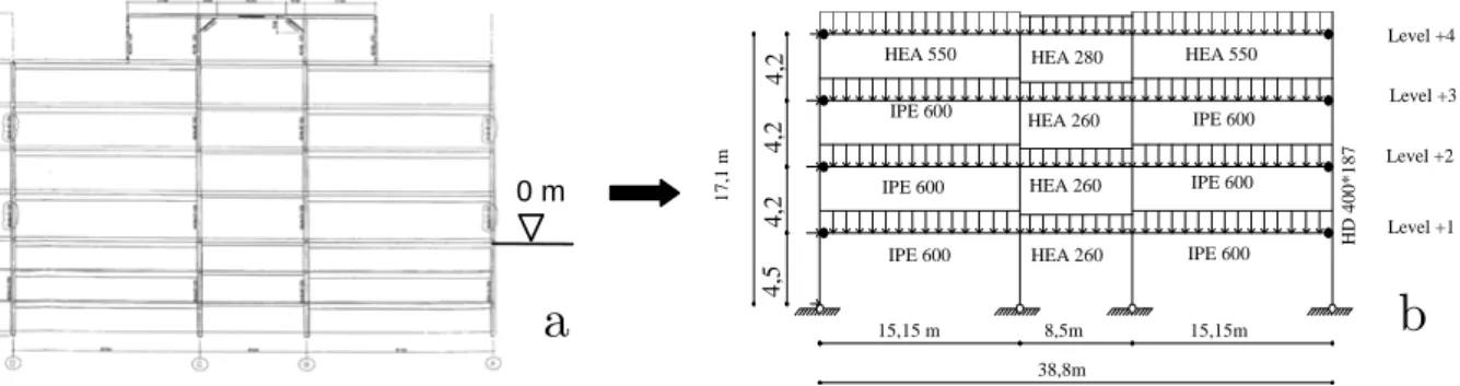
(6) 5.4.3 “Bochum” building..........................................................................................5-16 5.4.4 “Eisenach” building ........................................................................................5-20 5.4.5 “UK” building ..................................................................................................5-22 5.4.6 “Luxembourg” building ...................................................................................5-25 5.4.7 Conclusions ...................................................................................................5-28 5.5 CHAPTER CONCLUSIONS ..................................................................................................... 5-28. CHAPTER 6. : APPLICABILITY OF SIMPLIFIED ANALYTICAL METHODS................ 6-1. 6.1 INTRODUCTION ..................................................................................................................... 6-1 6.2 AMPLIFIED SWAY MOMENT METHOD ................................................................................... 6-3 6.2.1 Introduction ......................................................................................................6-3 6.2.2 Comparison of the results................................................................................6-3 6.3 MERCHANT-RANKINE APPROACH ........................................................................................ 6-5 6.3.1 Introduction ......................................................................................................6-5 6.3.2 Comparison of the results................................................................................6-5 6.3.3 Development of an alternative method for the “Bochum” building...................6-7 6.4 CHAPTER CONCLUSIONS ..................................................................................................... 6-10. CHAPTER 7. : GENERAL CONCLUSIONS.............................................................................. 7-1. 7.1 CONCLUSIONS OF THE NUMERICAL INVESTIGATIONS .......................................................... 7-2 7.2 CONCLUSIONS OF THE ANALYTICAL INVESTIGATIONS ......................................................... 7-4 7.2.1 Amplified sway moment method......................................................................7-4 7.2.2 Merchant-Rankine approach ...........................................................................7-5 7.3 PERSPECTIVES ...................................................................................................................... 7-7 REFERENCES. ANNEXES.
(7) Abstract In the last years, the construction of taller composite buildings and larger composite industrial halls without wind bracing systems is susceptible to make global instability a relevant failure mode; this one is not yet covered by Eurocode 4, which mainly deals with composite construction under static loading. Indeed, as far as the European codes are concerned, Eurocode 4 contains design procedures for non-sway composite buildings only and gives design rules for composite slabs, beams, columns and joints. That is why a research project on global instability of composite sway frames has been funded by the European Community for Steel and Coal (ECSC) for three years. The objective of this project was to provide background information on the behaviour of such frames under static and seismic loads and to provide simplified design rules by means of experimental and analytical investigations. The present work reflects parts of the investigations carried out by Liège University, as partner in the above-mentioned European project. The objective of this work is to analyse the behaviour of sway composite frames under static loading through numerical analyses and to investigate the applicability of simplified analytical methods initially developed for steel sway frames to composite ones. To achieve this goal, a benchmark study is first performed so as to demonstrate the validity the homemade finite element software FINELG for the numerical simulation of composite structures. Secondly, different numerical analyses on actual composite sway buildings submitted to horizontal and vertical static loads are realised with the so-validated FINELG software so as to predict their “actual” response and to highlight their particular behavioural aspects. Finally, the applicability to composite sway structures of two simplified analytical methods, initially developed for steel ones, is investigated; these two methods are the “Amplified sway moment method” and “Merchant-Rankine” approaches, respectively based on elastic and plastic design philosophies. In this part, an alternative method based on the “Merchant-Rankine” approach formulas is also introduced for the analytical prediction of the ultimate load factor of non-proportionally loaded sway frames..
(8) Notations - Aeq. : equivalent steel cross section of a composite member. - beff. : effective width of a composite beam. -E. : Young modulus. - Et. : strain hardening stiffness of the steel material. - fck. : characteristic elastic strength of the concrete material. - fy. : elastic strength of the steel material. -G. : sum of the self-weight and the permanent loads applied on a frame. -h. : height of a storey. -H. : total height of a building or a frame. - Ib. : moment of inertia of a beam cross section. - Ie. : equivalent moment of inertia of a composite member. -L. : length of a beam. - L0. : distance measured between consecutive points of contraflexure in the bending moment diagram of a beam for the determination of the composite beam effective width. - Me. : elastic resistance moment of a member cross section or a joint. - Mpl. : plastic resistance moment of a member cross section. - Mpl,Rd,+. : design plastic moment resistance of a composite beam under sagging moment. - Mpl,Rd,-. : designplastic moment resistance of a composite beam under hogging moment. - MRd. : design moment resistance of a joint. - MSd. : design moment acting at a joint. - nc. : number of full height columns per plane – parameter used for the computation of the initial out-of-plumb φini. - ns. : number of storeys – parameter used for the computation of the initial out-ofplumb φini. - Npl,Rd. : design plastic resistance of a composite column to gravity load without account of the buckling phenomenon.
(9) - Npl,Rd,buckling: design resistance of a composite column to gravity load with account of the buckling phenomenon - PRd. : design resistant load of a shear stud. -Q. : sum of the variable loads applied on a frame. - Sj,ini. : initial stiffness of a joint. - Vcr. : elastic critical load producing a global sway instability.. - Vn. : actual value of the shear forces introduced at a joint level in the column web panel. - Vpl,Rd. : design plastic resistance to shear forces of a member. - VRd. : design shear resistance of a joint or of a structural member. - Vsd. : total design vertical load applied to a structure. - yg. : position of the gravity centre of a cross section according to the lower fibre of the latter. -α. : factor applied to the concrete limit strength so as to take account of the long term loading effects. -δ. : deflection of a member relative to the chord line connecting its ends. -Δ. : horizontal top displacement of a structure. -φ. : rotation associated to the connecting parts of a joint. - φCd. : design rotation capacity of a joint. - φini. : rotation at the column bases associated to the initial global frame imperfection. -γ. : relative rotation between the beam and column axes associated to the column web panel in shear component of a joint. - λcr. : critical load factor – load factor at which global sway instability occurs in a structure (obtained through a critical elastic analysis). - λcr,cracked. : critical load factor computed assuming that the concrete is cracked in the support region (hogging moment zone). - λcr,uncracked : critical load factor computed assuming that the concrete is uncracked in the support region (hogging moment zone) - λe. : elastic load factor – load factor at which a first plastic hinge develops in a structure.
(10) - λp. : plastic load factor – load factor at which a plastic mechanism develops in a structure (obtained through a first-order rigid-plastic analysis). - λp,beam. : plastic load factor associated to a beam mechanism. - λp,combined : plastic load factor associated to a combined mechanism - λp,panel. : plastic load factor associated to a panel mechanism. - λsd. : design load factor. - λu. : ultimate load factor – load at which the failure of a structure is reached (obtained through a non-linear analysis). -θ. : joint rotation. - Ψbraced. : lateral flexibility of a structure with a bracing system. - Ψunbraced. : lateral flexibility of a structure without a bracing system.
(11) Chapter 1 : Introduction 1.1 Context Most steel-concrete composite structures are laterally restrained by efficient bracing systems, such as concrete cores. This practice does not favour the use of composite structures. Indeed, once concrete construction companies are involved into major parts of a building, the reason for using composite structures for subsequent parts is often questionable. As an alternative, moment resisting frames, without bracing systems, offer a flexible solution to the user of the buildings, especially for the internal arrangement and the exploitation of the buildings. When sufficient stiffness and strength with regard to lateral forces are achieved, such frames offer a structural solution, which can resist lateral loads. In seismic regions, properly designed moment resisting frames are the best choice regarding the available ductility and the capacity to dissipate energy. This is stated in Eurocode 8 devoted to earthquake engineering in which high values of the behaviour factor are recommended. Obviously, the construction of tall buildings and large industrial halls without wind bracing systems is susceptible to make global instability a relevant failure mode; this is not yet well covered by Eurocode 4 which mainly deals with composite construction under static loading. Indeed, as far as the European codes are concerned, Eurocode 4 contains design procedures for non-sway composite buildings only and gives design rules for composite slabs, beams, columns and joints. That is why a research project on global instability of composite sway frames has been funded by the European Community for Steel and Coal (ECSC) for three years (“Applicability of composite structures to sway frames” – Contract N° 7210-PR-250). The objective of this project was to provide background information on the behaviour of such frames under static and seismic loads and to provide simplified design rules as a result of experimental, numerical and analytical investigations: -. Concerning the experimental investigations, two main experimental tests were planned in the project: •. a 3-D composite building under dynamic loading tested in Ispra (Italy);. •. a 2-D composite frame under static loading tested in Bochum (Germany).. Beside these tests, cyclic and static tests on isolated joint were also performed in different European laboratories so as to get the actual behaviour of the constitutive joints of these two structures; the behavioural responses of the joints are known to significantly influence the global behaviour of the structure. -. Concerning the analytical investigations, they were divided in two parts:. Chapter 1: Introduction. 1-1.
(12) •. numerical analyses of existing structures further to a preliminary benchmark study aimed at validating the numerical tools used for the numerical investigations;. •. development of design guidance with proposals of simple analytical methods to design composite sway structures.. The present thesis reflects the analytical investigations carried out at Ulg as partner of the above-mentioned European project. The objectives of the work and the research steps followed in the present study are briefly described in the following paragraph.. 1.2 Objectives and research steps Composite sway structures are prone to global instability phenomena and to second-order effects; the latter have to be predicted carefully because they may govern the design. These second order effects are amplified by an additional source of deformability with regards to steel sway structures: the concrete cracking. Indeed, this effect, which is specific to concrete and composite constructions, tends to increase the lateral deflection of the frame, amplifies consequently the second-order effects and reduces the ultimate resistance of the frames. In other words, for a same number of hinges formed at a given load level in a steel frame and in a composite frame respectively, larger sway displacements are reported in the composite one. The objectives of the present thesis is to investigate the effects of these phenomena on the behaviour of composite sway frames, to highlight the particularities of their behaviour and to propose simplified analytical procedures for the design of such frames; these objectives will be achieved by means of numerical and analytical studies on plane frames extracted from actual buildings. The research steps are the following: -. Chapter 2 first gives a general overview of the available knowledge on composite structures and the design methods for sway structural systems. So, details about the sway effects in steel building frames and the design methods available in Eurocode 3 for steel sway frames are first given; then, design rules for composite elements, as given by Eurocode 4, are described.. -. After that, Chapter 3 describes in details the five composite buildings which have been considered in the numerical and analytical investigations. These buildings have been either built in Europe or tested in European laboratories.. -. The following chapter presents different software which have been developed in Liège for the evaluation of the geometrical and mechanical properties of the composite structural members; these software are used when required in the next chapters.. -. Chapter 5 presents and analyses the numerical investigations performed on frames extracted from the actual buildings presented in Chapter 3. The assumptions made to. Chapter 1: Introduction. 1-2.
(13) model numerically the studied frames are first introduced. Then, a benchmark study aimed at validating the finite element software used for the numerical investigations is described and its main results are detailed. Finally, the results of the numerical investigations obtained by means of the so-validated finite element software are presented and analysed to highlight their particular behavioural aspects. -. Then, the applicability to composite sway frames of two simplified analytical methods commonly used for steel frames is contemplated in Chapter 6: the “amplified sway moment method” and the “Merchant-Rankine approach”. Indeed, these methods initially developed for steel sway frames cannot be applied to composite sway frames in a straightforward way as the latter present an additional deformation source which is the concrete cracking. The results obtained through these methods are compared to the ones obtained through non-linear analyses presented in the previous chapter.. -. Finally, general conclusions are presented in Chapter 7 with a summary of the main results and the perspectives for future studies which should be presented in our future PhD thesis.. Chapter 1: Introduction. 1-3.
(14) Chapter 2 : State-of-the-art knowledge on composite sway building frames 2.1 Introduction As said in § 1.1, Eurocode 4 limits its scope to “non-sway” composite buildings under static loading, giving rules to analyse and to check elements like composite slabs, beams, columns and joints. No rules are given for the analysis and the verification of “sway” composite building frames; Eurocode 4 only recommends to use “appropriate” design rules for such frames. Few information about the behaviour of composite sway frames are available until now; first investigations in this field have been carried out in the last years. In particular, the applicability of the wind-moment method (see § 2.2.6.6) to unbraced composite frames was first examined in a Ph.D thesis [1] submitted at Nottingham University; the use of this method for composite sway building frames will be discussed later on in Chapter 6. Two diploma works ([2] and [3]) with the objective of investigating the behaviour of sway composite structures were also submitted at Liège University; part of the obtained results will be presented later on in Chapter 5. This chapter introduces the different concepts available in the actual codes, which will be the starting points for the developments presented in this work: -. § 2.2 first details the design methods proposed in Eurocode 3 for the analysis and the check of steel sway building frames;. -. then, § 2.3 presents the design rules proposed in Eurocode 4 for the design of the composite building constitutive elements.. 2.2 Sway effects in steel building frames 2.2.1 Introduction Sway frames are characterised by significant lateral displacements. The latter can generate a global instability phenomenon under the gravity loads, as a result of second-order effects called “P-Δ effects” (see § 2.2.4.2) which can significantly influence the behaviour of the frame. Furthermore, under increasing external loading, the apparition of plastic hinges in the frame decreases progressively its lateral stiffness; this has a detrimental influence on the maximum vertical loads leading to a global frame instability. Eurocode 3, dedicated to steel buildings, is the only structural code providing indications on how to deal with the instability and, in particular, with the global frame analysis methods. Global frame analysis aims at determining the distribution of the internal forces and of the. Chapter 2: State-of-the-art knowledge on sway composite building frames. 2-1.
(15) corresponding deformations in a structure subjected to a specified loading. It requires the adoption of adequate models which incorporate assumptions on the behaviour of the structure and in particular of its constitutive members and joints. And, these assumptions may be different if the structural building is “sway” or a “non-sway”. In the section, the procedure proposed in Eurocode 3 for the analysis and the verification of a steel sway frame is described; the applicability of the latter to sway composite frames is investigated in Chapter 5 and Chapter 6. The paragraphs are organised as follows: -. First, the idealisation of actual buildings is described in § 2.2.2.. -. Secondly, a general description of the criteria for the member cross section and the frame classification is given in § 2.2.3 and 2.2.4 respectively.. -. The possible global frame analyses are then briefly described in § 2.2.5 together with the different criteria which govern their choice; the different verifications to perform according to the selected analysis method are also presented.. -. Finally, simplified analytical methods developed for steel sway frames are introduced in § 2.2.6; these methods allow the designer to proceed to a rather simple structural design (not requiring a high capacity software to take account of the sway effects and the non-linearities).. Remark: these paragraphs are largely inspired by the following lecture notes prepared within a European project in which ULg has been deeply involved: “Structural Steelwork Eurocodes – Development of a Trans-national Approach (SSEDTA)” ([4], [5] & [6]).. 2.2.2 Frame idealisation Global analysis of frames is conducted on a model based on many assumptions including those for the structural model, the geometric behaviour of the structure and of its members and the behaviour of the sections and of the joints. A 3-D structure is composed of “members” linked together through joints and has to respect resistance, stability and serviceability conditions; each element has their own characteristics and has also to respect the same conditions. Members are classified according to their cross section properties (see § 2.2.3) or the kind of loading they sustain. They are termed as beams if bending predominates, as columns (compression members or tension members) if axial load predominates and as beam-columns if significant amounts of both bending and axial load are present. A brief description of each type of members is given here below: -. In a general way, beams are designed to carry loads which produce in-plane bending (bi-axial bending is rare in such members). Because unavoidable initial imperfections in the beam geometry and unintentional small eccentricity of the loads on the beam occur, some torsion will be always present in the case of in-plane bending. Under increasing loads, the out-of-plane deformations can become magnified to such an. Chapter 2: State-of-the-art knowledge on sway composite building frames. 2-2.
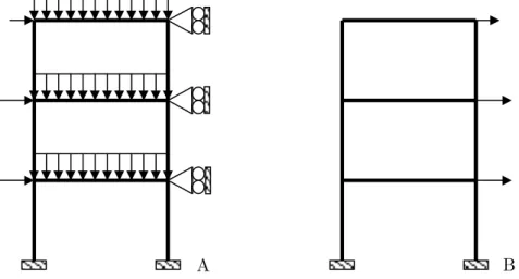
(16) extent that the usefulness limit of the beam may be reached. Failure is then said to occur due to lateral-torsional buckling. For most typical frames this type of failure can usually be avoided by providing adequate lateral restraint to the compression flange (restraint provided in the plane of the floor or by the floor slab itself for instance). Beams are made up of plate elements, which may sometimes be sensitive to local buckling. Local buckling in combination with lateral-torsional buckling may be the cause of failure of some steel beams in a structure. -. Columns are designed to carry axial tension or compression forces. When a column is subjected to axial compression, it may be classified by length. Whilst a short compression member fails by crushing or squashing, a long or slender compression member fails by buckling instability. The squash load occurs where there is full plastification in compression throughout the cross section of the member. The failure load of any compression member that fails by buckling depends on its slenderness and, as a consequence, the buckling load of the member can be significantly lower than its squash load. The design resistance of tension members is based on yield in the gross section and/or on rupture in the net section. Special attention has to be paid to where ductile behaviour is required.. -. Members subject to both significant bending and axial compression are called beamcolumns. Such members are typically the vertical members of a frame structure. Members subject to both significant bending and axial tension can be included in this category. Strictly speaking, most members are beam-columns; beams represent the limiting case where the axial forces can be disregarded and columns are the limiting case where bending moments are not significant.. The links between the different members are the joints. Historically, it has been common practice to assume joints to be either rigid or pinned. Whilst it is still usual today, it is now possible to model joint behaviour more precisely and to introduce their actual behaviour in the analysis (see § 2.3.5). The main forces that a joint between two members must transmit are the shear forces and, when the joint is not pinned, the in-plane bending moment. As an alternative to analysing the main structure as a one three-dimensional framework, it may be analysed as two series of independent plane frames running in two horizontal directions approximately at right angles to each other (Figure 2-1) provided each such plane frame has sufficient out-of-plane restraint to ensure its lateral stability.. Chapter 2: State-of-the-art knowledge on sway composite building frames. 2-3.
(17) Figure 2-1: from a 3-D framework to 2-D frames. 2.2.3 Member cross section classification Member sections, be they rolled or welded, may be considered as an assembly of individual plate elements, some of which are internal (e.g. the webs of open beams or the flanges of boxes) and others are outstand (e.g. the flanges of open sections and the legs of angles). As the plate elements in structural sections are relatively thin compared with their width, when loaded in compression (as a result of axial loads applied to the whole section and/or from bending) they may buckle locally.. The disposition of any plate element within the cross. section to buckle may limit the axial load carrying capacity, or the bending resistance of the section, by preventing the attainment of yield. Avoidance of premature failure arising from the effects of local buckling may be achieved by limiting the width-to-thickness ratio for individual elements within the cross section. This is the basis of the section classification approach. Eurocode 3 (and also Eurocode 4) defines four classes of cross section. The class into which a particular cross section falls depends upon the slenderness of each element (defined by a width-to-thickness ratio) and the compressive stress distribution i.e. uniform or linear. The classes are defined in terms of performance requirements for resistance of bending moments: -. Class 1 cross sections are those which can form a plastic hinge with the required rotational capacity for plastic analysis.. -. Class 2 cross sections are those which, although able to develop a plastic moment (Mpl), have limited rotational capacity and are therefore unsuitable for structures designed by plastic analysis.. -. Class 3 cross sections are those in which the calculated stress in the extreme compression fibre can reach yield but local buckling prevents the development of the plastic moment resistance.. -. Class 4 cross sections are those in which local buckling limits the moment resistance (or compression resistance for axially loaded members); the elastic moment (Me) cannot develop in such sections. Explicit allowance for the effects of local buckling is necessary.. Chapter 2: State-of-the-art knowledge on sway composite building frames. 2-4.
(18) M 1 2. M pl 3. M el 4. θ. Figure 2-2: shape of the moment-rotation curve according the class of the section. So, the choice between an elastic or a plastic analysis will be mainly govern by the class of the cross sections of the structural members (see § 2.2.5).. 2.2.4 Frame classification 2.2.4.1. Braced and unbraced. At a preliminary design stage, a decision usually has to be made as to whether the structure is to have a braced or unbraced classification. This determines how the vertical and horizontal load effects (including those due to frame imperfections) are to be considered in the analysis. When bracing is provided it is normally used to prevent, or at least to restrict, sway in multi-storey frames. Common bracing systems are trusses or shear walls (Figure 2-3). Trusses. Shear wall. Figure 2-3: common bracing systems. For a frame to be classified as a braced frame, it must possess a bracing system which is adequately stiff. Indeed, the existence of a bracing system in a structure does not guarantee that the frame structure is to be classified as braced. Only when the bracing system reduces the horizontal displacements by at least 80% can the frame be classified as braced: -. if no bracing system is provided: the frame is unbraced;. Chapter 2: State-of-the-art knowledge on sway composite building frames. 2-5.
(19) -. if a bracing system is provided: the frame is braced when Ψbraced ≤ 0,2 Ψunbraced where. Ψbraced is the lateral flexibility of the structure with the bracing system andΨunbraced is the lateral flexibility of the structure without the bracing system. When it is justified to classify the frame as braced, it is possible to analyse the frame and the bracing system separately as follows : -. The frame without the bracing system can be treated as fully supported laterally and as having to resist the action of the vertical loads only.. -. The bracing system resists all the horizontal loads applied to the frames it braces, any vertical loads applied to the bracing system and the effects of the initial sway imperfections from the frames it braces and from the bracing system itself.. For frames without a bracing system and also for frames with a bracing system but which is not sufficiently stiff to allow classification of the frame as braced, the structure is classified as unbraced. In all case of unbraced frames, a single structural system, consisting of the frame and of the bracing when present, shall be analysed for both the vertical and horizontal loads acting together as well as for the effects of imperfections.. 2.2.4.2. Sway and non-sway o. Second-order effects. Prior to the definition of the sway – non-sway classification, it is important to define the underlying concept of “second-order effects”. The second order theory consists in expressing the equilibrium between the internal and external forces of the structure in the deformed shape; in opposite, a first-order theory expresses the equilibrium in the undeformed shape. As an example, Figure 2-4 shows that an additional level arm for the vertical loads appears with account for the deformation of the structure; so, additional bending moments develop in the structure (called “second-order bending moments”). P H. Sway Load. H. Δ. P. Displacement. x. x h. Frame. δ. M(x) = Hx. M(x) = Hx +Pδ + P Δ x / h. M(h) = Hh. M(h) = Hh + P Δ. where h is the height from the column base to the inflexion point Δ is the sway relative to the column base of the infexion point. Figure 2-4: first-order and second-order moments in a beam-column. Chapter 2: State-of-the-art knowledge on sway composite building frames. 2-6.
(20) These global second-order moments are commonly referred to as the P-Δ effects. In addition a local second-order moment, commonly referred to as the P-δ effects, arises in the axially loaded member due to the deflections (δ) relative to the chord line connecting the member ends (Figure 2-4). These second-order effects are initiated by the global frame imperfections and the local member imperfections which are present in all structures (Figure 2-5). N. L. ΦΦini. eo,d. ΦΦini. (b). (a). Figure 2-5: global frame initial imperfection (a) and local member initial imperfections (b). o. Sway – non-sway classification. The term non-sway frame is applicable when the frame response to in-plane horizontal forces is sufficiently stiff for it to be acceptable to neglect any additional forces or moments arising from horizontal displacements of its nodes. The global second-order effects (i.e. the P- Δ sway effects) may be neglected for a non-sway frame. When the global second-order effects are not negligible, the frame is said to be a sway frame.. Braced frame. Unbraced frame. (may be sway if bracing is very flexible). (may be non-sway if not sensitive to horizontal loads). Figure 2-6: braced and unbraced frame. Normally a frame with bracing is likely to be classified as non-sway, while an unbraced frame is likely to be classified as sway. However, it is important to note that it is theoretically possible for an unbraced frame to be classified as non-sway (this is often the case of one storey portal frame buildings) while a frame with bracing may be classified as sway (possible for multi-storey buildings) (Figure 2-6). When a frame is classified as non-sway, a first-order analysis may always be used; when a frame is classified as sway, a second-order analysis shall be used.. Chapter 2: State-of-the-art knowledge on sway composite building frames. 2-7.
(21) The classification of a frame structure as sway or non-sway is based on the value of the ratio of the design value of the total vertical load VSd applied to the structure to its elastic critical value Vcr producing sway instability (failure in the sway mode). Obviously, the closer that the applied load is to the critical load, the greater is the risk of instability and the greater are the global second-order effects on the structure (the P-Δ effects). The classification rule is as follows: V - if sd ≤ 0.1 (2.1), the structure is classified as non-sway; Vcr V - if sd > 0.1 (2.2), the structure is classified as sway. Vcr This rule can also be expressed in the following way:. -. 2.2.4.3. Vcr ≥ 10 (2.3), the structure is classified as non-sway; VSd V if λcr = cr < 10 (2.4), the structure is classified as sway. VSd. if λcr =. Summary. The different possibilities of frame classification can be summarized by Table 2-1 where all the combinations between braced – unbraced and sway – non-sway are presented. Table 2-1: possibilities of frame classification. Braced. Unbraced. Non-sway. Sway. The choice between a first-order or a second-order theory for the global structural analysis will mainly be governed by the frame classification (see § 2.2.5).. 2.2.5 Types of structural analyses and associated verifications 2.2.5.1. Introduction. The previous paragraphs have introduced the different classifications for the member cross sections and for the frames; these classifications will mainly influence the selection of the global structural analysis to perform on the frame.. Chapter 2: State-of-the-art knowledge on sway composite building frames. 2-8.
(22) On one hand, the class of the member cross section influence the choice between a plastic or an elastic analysis: plastic analyses can only be applied to structures which present member cross sections of class 1 where plastic hinges take place; if it is not the case, only the realization of an elastic analysis is authorized. On the other hand, the classification of the frame will influence the choice between a firstorder and a second-order theory. The different possibilities are presented in Table 2-2. Table 2-2: influence of the frame classification on the choice between a first or second order theory. Non-sway. Sway. Braced. Unbraced. First order theory. First order theory. or. or. Second order theory. Second order theory. Second order theory. Second order theory. One aspect which has also to be considered in this choice is that the design checks to be carried out after the analysis depend on the sophistication of the analysis “tool” used (see Figure 2-7): the number of design checks decreases with the increase of the analysis sophistication (from first-order elastic analysis to “full” non-linear analysis).. Share of effort. Simplification of global analysis. Global analysis. ULS checks. Sophistication of global analysis Figure 2-7: balance between global analysis and ultimate limit states (ULS) checks. The present paragraph presents the different type of structural analysis which can be applied to frames. For each type, the different ultimate limit states (ULS) checks to perform are described. The serviceability limit states (SLS) have also to be verified; the different limitations recommended in Eurocode 3 (and in Eurocode 4) are presented in Table 2-3 where L is the length of a beam, H the total height of the structure and h the height of a storey. A last paragraph (§ 2.2.5.8) compares the results obtained through the different analyses described in this paragraph through a qualitative illustration in Figure 2-8.. Chapter 2: State-of-the-art knowledge on sway composite building frames. 2-9.
(23) Table 2-3: deflection limitations recommended in Eurocode 3 and 4 Verification. Limitation. Beam deflection. L/300. Top sway displacement. H/500. Sway displacement for each storey. h//300. Remark: for all the presented analyses, the out-of-plane stabilities have to be checked. This point will not be reminded in the following paragraphs.. 2.2.5.2. First-order elastic analysis. Linear elastic analysis implies an indefinite linear response of sections and joints. This analysis is applicable to non-sway buildings. It can be used for sway frames under certain conditions and provided that appropriate corrections are made to allow for the second-order effects when necessary (see § 2.2.6); this is the only restriction to this type of analysis. The main advantage of such analysis is that the superposition principle is applicable. As elastic analysis is used, it would seem appropriate to consider the attainment of the yield stress in the extreme fibres of the most loaded section as the design condition for a member; however, in usual cases, it is generally accepted that an elastic analysis can be safely used to determine the load corresponding to when the first plastic event occurs (if the class of the member cross section where the plastic event occurs permits it). However, this assumes that the structure (in case of sway frames) and its members remain stable. So, it is important to check the stability of the structure and its members (buckling, lateral-torsional buckling) to be sure that an instability phenomenon does not decrease the design resistance value.. 2.2.5.3. Critical elastic analysis. This analysis is based on the same assumption as the previous one (sections and joints indefinitely linear elastic) and is achieved so as to derive the elastic critical load Vcr (or the elastic critical load factor λcr) that corresponds to the first mode of global instability. According to Eurocode 3 [7], this value is used through the evaluation of the VSd/Vcr (or. λSd/λcr) ratio - VSd being the design vertical applied load - to determine whether a frame is laterally rigid or, in contrast, prone to sway (see § 2.2.4.2).. 2.2.5.4. Second-order elastic analysis. In this type of analysis, the indefinitely linear-elastic response of sections and joints is still applied. The distribution of the internal forces is now computed on the basis of a secondorder theory (i.e. equilibrium equations express in the deformed structure). This type of analysis is applicable to all structures.. Chapter 2: State-of-the-art knowledge on sway composite building frames. 2-10.
(24) As for the first-order elastic analysis, the failure is assumed to be reached when the extreme fibres of the most loaded section yields or when the first plastic hinge takes place in the structure (if the member cross section class permits it). The resistance of the sections and of the joints has to be checked. As the P-Δ effects (§ 2.2.4.2) are considered in a second-order analysis, it is not needed to check the global stability of the structure. If the P-δ (§ 2.2.4.2) effects are also included in the analysis, neither have the local stability to be checked; if it is not the case, it has to be verified but by computing the buckling length with the assumption of a non-sway structure, as the sway effects are included in the analysis.. 2.2.5.5. First-order rigid-plastic analysis. In such analysis, the elastic deformations are ignored. This type of analysis is especially appropriate for non-sway frames while its use for sway frames is limited to specific cases; the latter is only applicable to structures which fulfil some conditions given in EC3 (steel properties, cross section class,...). This calculation results in the first-order rigid-plastic load factor λp; the latter is often called the first-order “limit” load factor. It can be obtained easily by hand-calculation, or by using appropriate software. The first-order rigid-plastic load factor is required, for instance, to apply the simplified design method known as the “MerchantRankine approach” (see § 2.2.6.4). Adequate design requires that the value of the load multiplier λp be at least unity. As the first-order plastic method does not make allowance for any buckling phenomena as well at a local as at a global level, these checks shall be carried out with due allowance being made for the presence of plastic hinges.. 2.2.5.6. Second-order rigid-plastic analysis. This analysis may be used in all cases for which a plastic analysis is allowed. This analysis differs from the previous one by the fact that equilibrium equations are now expressed with reference to the deformed frame configuration. A second-order rigid-plastic analysis gives an indication on how second-order effects develop once the first-order rigid-plastic mechanism is formed and how much they affect the postlimit resistance. Because second-order effects are without significant influence on the plastic beam mechanisms, the second-order rigid-plastic response curve will not diverge notably from the one obtained from a first-order rigid-plastic analysis. In contrast, for panel and combined beam-panel plastic mechanisms, the larger the sway displacement, the more the second-order rigid-plastic load factor is reduced when gravity loads increase. Concerning the stability of the studied structure and its constitutive elements, the remarks introduced for the first-order rigid-plastic analysis (in the previous paragraph) are also valid. Chapter 2: State-of-the-art knowledge on sway composite building frames. 2-11.
(25) for the second-order rigid-plastic analysis except that it is not needed here to check the global stability of the structure as the P-Δ effects are involved in the analysis.. 2.2.5.7. Non-linear analysis. A non-linear analysis is applicable to all cases. In this type of analysis, all the geometrical and material non-linearities are considered: realistic material stress-strain curves, semi-rigid response of the joints and second-order effects induced by frame and element geometrical imperfections. The initial deformation of the buildings is introduced in the analysis. Such an analysis enables an accurate estimation of the actual ultimate load factor λu. The stability of the structure and the constitutive elements doesn’t need to be checked, as P-Δ and P−δ effects are involved in the non-linear analysis.. 2.2.5.8. Overview of the considered frame analyses. In Figure 2-8, the results of the different analyses described in this paragraph are qualitatively illustrated. This figure shows how the sway displacement Δ influences the value of the load factor λ got from the several types of analysis. λ M λ cr. Load factor. λP. A. B. L. JJ. E. F. λu. C. K. D. H 1. 0. G W. ΔW ΔE. ΔK. ΔH. Δ. Deflection. Figure 2-8: graphical representation of the results obtained through the different structural analyses. The line “OA” corresponds to a purely elastic first-order analysis. The result of the elastic critical analysis is given by the horizontal line “ML”, the ordinate of which corresponds to the elastic critical load factor λcr. Curve “OJL” corresponds to the second-order elastic analysis; this curve approaches asymptotically the horizontal line “ML” corresponding to the elastic critical analysis result. The first-order rigid-plastic analysis is represented by the curve “OBC”; when the first-order rigid-plastic load factor λp is reached (in “B”), the failure develops under constant load (“BC” line). The behaviour got from the second-order rigidplastic analysis is represented by the “OBD” curve: when the rigid-plastic load factor λp is reached (in “B”), its value decreases with an increasing transverse displacement (“BD” curve). The “OFG” curve results from a non-linear analysis; it is likely to reflect the “actual”. Chapter 2: State-of-the-art knowledge on sway composite building frames. 2-12.
(26) frame behaviour. The ultimate load factor λu corresponds to the peak ordinate of the loaddisplacement curve (in “F”). If, at λu, the failure of the structure is due to the formation of a full plastic mechanism, the “actual” behavioural curve “OFG” obtained through the nonlinear analysis and the line “OBD” relative to the second-order rigid-plastic analysis join at point “F”, in this particular case, point “F” should correspond to point “K” in Figure 2-8. If a global frame instability occurs before the development of a plastic mechanism, the “actual” curve remains below the second-order rigid-plastic one “OBD” and point “F” differs from point “K”. This situation is the one illustrated in Figure 2-8.. 2.2.6 Simplified analytical methods for steel sway frames 2.2.6.1. Introduction. Several simplified analytical methods for frame analysis and design exist and some of them are proposed in Eurocode 3 [7]. These methods allow the designer to proceed to structure design without high capacity software which could take account of the sway effects and the non-linearities. Some of them are briefly described in this paragraph. These methods assume that the materials and the joints have linear or rigid-plastic behaviours and are based on physical and empirical approaches of the problem; the proportion between the two types of approaches depends of the chosen method. They permit to derive a design load resistance which allows to verify the ULS; nevertheless, the SLS should also be verified for the studied structure. This point will not be recalled in the following paragraphs.. 2.2.6.2. Amplified sway moment method. This simplified analytical method is proposed in Eurocode 3 [7]. In this method, first-order linear elastic analyses are first carried out; then, the resulting internal forces are amplified by a “sway factor” so as to ascertain for second-order sway effects. Finally, the design load resistance of the frame is derived by computing the load at which a first plastic hinge develops in the frame (Æ the elastic load factor λe is derived). The steps to be crossed when applying this elastic design procedure are as follows:. -. A first-order elastic analysis is performed on the frame fitted with horizontal supports at the floor levels (Figure 2-9.A); it results in a distribution of bending moments in the frame and reactions at the horizontal supports.. -. Then, a second first-order elastic analysis is conducted on the initial frame subjected to the sole horizontal reactions obtained in the first step (Figure 2-9.B); the resulting bending moments are the so-called “sway moments”.. Chapter 2: State-of-the-art knowledge on sway composite building frames. 2-13.
(27) Approximate values of the “actual” second order moments result from the summing. -. up of the moments obtained respectively in the two frame analyses, after having amplified the sole sway moments by means of the sway factor:. 1 V 1- sd Vcr. (2.5). where Vsd is the design vertical applied load and Vcr is the lowest elastic critical load associated to a global sway instability.. -. The maximum elastic resistance of the frame is reached as soon as a first plastic hinge forms in the frame.. A. B. Figure 2-9: static schemes used for the amplified sway moment method. Above design procedure is rather simple, as it only requires first-order elastic analyses. Also the principle of superposition remains applicable, what is especially useful when having to combine several individual loading cases. According to Eurocode 3 [7], the amplified sway moment method is restricted to structures characterized by Vsd/Vcr ranging from 0.1 to 0.25. The global stability check is involved in the method. For the in-plane local buckling check of the members, the buckling length for the non-sway mode is used in conjunction with the amplified moments and forces. Out-of-plane stability has also to be checked.. 2.2.6.3. Sway-mode buckling length method. The Sway-mode buckling length method is another indirect method to allow for second-order sway effects when using a first-order elastic analysis and is close to the previous method. It may be adopted for structures for which the sway sensitivity is unknown. The internal forces (moments, shear and axial forces) are computed on the basis of a firstorder analysis. The sway moments in beams and joints are then amplified by a nominal factor of 1,2 and afterwards added to the remainder of the moments (those not due to sway).. Chapter 2: State-of-the-art knowledge on sway composite building frames. 2-14.
(28) The so-obtained amplified forces are used for the design checks of joints and member cross sections and member in-plane and out-of-plane stability. The global stability check is included in the method; when checking in-plane local buckling of the members, the sway mode buckling length must be used for member design, which is a main difference according to the amplified sway moment method. Out-of-plane stability must also be checked. This method often gives too safe results, which explains the fact that this method is rarely used.. 2.2.6.4. Merchant-Rankine approach. The origin of this method is described in [8]. The Merchant-Rankine method is a secondorder elasto-plastic approach, which was developed for bare steel frames; it allows to assess the ultimate load factor through a formula that takes account of interactions between plasticity (λp) and instability (λcr) in a simplified and empirical way. A direct comparison with the ultimate load factor λu got through a non-linear analysis may be achieved. The Merchant-Rankine basic formula (“MR”) writes:. 1 1 1 = + λu λcr λ p. (2.6). or:. λu =. λp 1 + (λ p / λcr ). > / λp. (2.7). Should the frame be very stiff against sway displacements, then λcr is much larger than λp with the result of a low λp/λcr ratio: a minor influence of the geometrical second-order effects is expectable and the ultimate load is therefore close to the first-order rigid-plastic load. In contrast, a flexible sway frame is characterised by a large value of the λp/λcr ratio. It shall collapse according to a nearly elastic buckling mode at a loading magnitude, which approaches the elastic bifurcation load. Strain hardening tends to raise plastic hinge moment resistances above the values calculated from the yield strength. Therefore most practical frames with only a few storeys in height attain a failure load at least equal to the theoretical rigid-plastic resistance. When the ratio. λcr/λp is commonly greater than 10, the effects of material strain hardening more than compensate those of changes in geometry. Sometimes, additional stiffness due to cladding is sufficient to compensate such changes. To allow, in a general treatment for the minimum beneficial effects to be expected from both strain hardening and cladding, Wood suggested a slightly modified Merchant-Rankine formula (“MMR”):. λu =. λp 0.9 + (λ p / λcr ). > / λp. Chapter 2: State-of-the-art knowledge on sway composite building frames. (2.8). 2-15.
(29) in the range λcr/λp ≥ 4. He recommended not to use it in practice when λcr/λp < 4 but to carry a non-linear analysis in this range. When λp/λcr ≤ 0.1, λu is limited to λp, what means that the frame can be designed according to the simple first-order rigid-plastic theory. A clear and direct relationship may be established between this criterion and the one, which enables, according to Eurocode 3 [7], to classify steel frames as sway (VSd/Vcr > 0,1) or rigid (VSd/Vcr ≤ 0,1). Similarly, the limitation of the field of application of the amplified sway moment method to Vsd/Vcr values lower than 0,25 is seen to be strongly related to the here-above expressed λcr/λp ≥ 4 range of application of the modified Merchant-Rankine formula. The use of Formula (2.8) is commonly restricted to frames in buildings, in which: 1. the frame is braced perpendicular to its own plane; 2. the average bay width in the plane of the frame is not less than the greatest storey height; 3. the frame does not exceed 10 storeys in height; 4. the sway at each storey, due to non-factored wind loading, does not exceed 1/300 of the storey height; 5. λcr/λp ≥ 4. From complementary studies carried out at Liège University [8], the “MMR” approach is seen to exhibit a different degree of accuracy according to the type of first-order rigid-plastic failure mode which characterises the frame under consideration:. -. safe. for beam plastic mechanisms;. -. adequate. for combined plastic mechanisms;. -. unsafe. for panel plastic mechanisms.. As a result, the application of the “MMR” approach to structures exhibiting a first-order panel plastic mechanism should therefore be prohibited. In [8], the scope of the “MMR” formula is extended to structures with semi-rigid and/or partial-strength joints. The global stability check is involved in the “MR” and “MMR” methods but the local stability of the members must be checked.. 2.2.6.5. Simplified second-order plastic analysis. As an alternative to a second-order elastic-plastic analysis, Eurocode 3 [7] allows the use of rigid-plastic first-order analysis for particular types of sway frames. As for the indirect methods with first-order elastic analysis, the second-order sway effects are accounted for indirectly by multiplying moments (and associated forces) by a similar magnification factor. However in this case, all of the internal moments (and associated forces) are magnified (and. Chapter 2: State-of-the-art knowledge on sway composite building frames. 2-16.
(30) not just those due to sway alone as it is done in the elastic analysis case – see § 2.2.6.2 and 2.2.6.3). The limitation imposed on its use excludes the use of slender members for which member imperfections would have to be accounted for. The magnification factor is the same as for the first-order elastic analysis (Formula (2.5)). M. Pecquet demonstrated in his diploma work [3] that this method is equivalent to the Merchant-Rankine approach if this method is used so as to predict the ultimate load factor. λu; so, this method will not be presented with more details.. 2.2.6.6. Wind moment method. The wind moment method is a British one (mainly used in North America and UK) which is fully empirical. It is closer to a pre-design method than an analytical one. It permits the predesign of sway structures with semi-rigid joints. The distinguishing factors of this method, that set it apart from other methods, is the assumptions that are used during the design stage [1]:. -. under gravity loads, the connections are assumed to act as pins (Figure 2-10.a);. -. under wind loads the connections are assumed to behave as rigid joints, with points of contraflexure occurring at mid-height of the columns and at mid-span of the beams (Figure 2-10.b).. Figure 2-10: internal moments and forces according to the wind-moment method [1]. The first step in the design sequence is to design the beams under gravity loads. Then the frame is analysed under horizontal wind loads, with the assumption that the beam-to-column connections behave in a rigid manner. The internal forces and moments are then combined using the principle of superposition. The design for ULS is then completed by amending the initial section sizes and connection details, to withstand the combined effects. P-Δ effects are accounted for by designing the columns using effective lengths that are greater than the true column lengths. The sway displacements are computed assuming the beam-tocolumn joints are rigid; a sway factor is used to account for their true behaviour. The advantage of this method is its simplicity, as the frame is rendered statically determinate. Nevertheless, the horizontal beams tend to be overdesigned (as the joints at. Chapter 2: State-of-the-art knowledge on sway composite building frames. 2-17.
(31) their extremities are assumed to be hinges) when vertical columns tend to be underdesigned (as the bending moments coming from the beams are neglected). The joints are also overdesigned as hogging moments coming from the vertical loads are neglected.. 2.2.7 Conclusions In § 2.2, we have described in details the different steps to cross for the selection of a global structural analysis according to EC3 and the structural analyses available for the determination of the internal forces of a frame; the different verifications to perform which are associated to the chosen analysis have also been described. In addition, we have also introduced in § 2.2.6 simplified analytical methods available for steel sway frames. Some of the global structural analyses presented in this paragraph will be applied to sway composite frames through the numerical investigations presented in Chapter 5. The applicability of some simplified analytical methods developed for steel sway frames to composite ones will be investigated in Chapter 6.. 2.3 Composite structures 2.3.1 Introduction Eurocode 4 [15] presents design rules for non-sway steel-concrete composite buildings and gives mainly rules to analyse and to check structural elements like beams, columns, slabs and joints. The present paragraph is devoted to the presentation of the main characteristics of the constitutive elements of a composite structure (Figure 2-11): composite slabs (§ 2.3.2), composite beams (§ 2.3.3), composite columns (§ 2.3.4) and composite joints (§ 2.3.5). The objective of the paragraph is not to describe all the design procedures for these elements but to introduce the properties and rules which will be used in the following chapters. This paragraph is inspired by the following documents:. -. Lectures from SSEDTA ([10], [11] and [12]);. -. “Composite construction elements” of R. Maquoi and F. Cerfontaine [13];. -. Eurocode 4 ([9] and [15]);. -. COST C1 document [14].. Chapter 2: State-of-the-art knowledge on sway composite building frames. 2-18.
(32) composite slab. composite beam composite column. floor = beam + slab. Figure 2-11: composite buildings with its constitutive elements. 2.3.2 Composite slabs All the structures studied in the thesis are structures with composite slabs (see Chapter 3): concrete slab with a collaborating profiled steel sheeting (Figure 2-12). The main advantages of this type of slab are:. -. the profiled steel sheeting provides an excellent safe working platform at the working stage which speeds the construction process;. -. the steel sheeting is a structural part of the slab as it can be considered as tensile reinforcement at the bottom of the hardened concrete slab.. In a composite slab, an interlock must be provide to ensure the interaction between the steel and the concrete elements. These interlocks can be of several types as:. -. chemical interlock which is very brittle and unreliable (not consider in the computations);. -. frictional interlock which is not able to transfer large shear forces;. -. mechanical interlock by interlocking embossments of the steel decking;. -. end anchorage like headed bolts, angle studs or end-deformations of the steel sheeting which brings a very concentrated load introduction at the ends.. Figure 2-12: example of composite slabs. According to Eurocode 4 [9], the verifications of composite slabs for the ULS include (when the concrete is hardened):. Chapter 2: State-of-the-art knowledge on sway composite building frames. 2-19.
(33) -. the verification of the bending resistance under sagging and/or hogging moments at the critical cross sections;. -. the verification to the longitudinal shear with or without end anchorage;. -. the verification to the vertical shear;. -. the verification to the punching shear.. The verifications for the SLS involve the check of the concrete cracking in hogging moment regions, the verification of the deflections and the verification for the vibrations.. 2.3.3 Composite beams A composite beam is composed of a steel beam connected to a concrete or composite slab through shear connectors which ensure the collaboration between the steel and the concrete elements. In the studied structures (see Chapter 3), all the composite beams are I steel profiles connected to composite slabs through stud shear connectors; in some cases, the I steel profiles can be partially-encased ones (Figure 2-13).. Figure 2-13: examples of composite beams (I steel profiles connected to composite slabs). In sagging moment regions, compression stresses are introduced in the concrete slab through the connectors. The induced stress distribution in the slab is not uniform: it is higher close to the steel beam and decreases progressively away from the beam. This phenomenon is known as shear lag. In order to treat a composite floor as an assembly of independent tee-sections, the concept of an effective width beff of the slab is introduced (Figure 2-14); a width of slab is associated with each beam such that the normal flexural constraint calculated by Navier's assumption and applied to the composite section thus defined, would provide the same maximum constraint as that originating in the actual non-uniform distribution. The value of beff depends, in quite a complex manner, on the relation of the spacing 2bi (see Figure 2-14) to the span L of the beam, on the type of load, on the type of supports to the beam, on the type of behaviour (elastic or plastic) and on other factors besides. That is why in the domain of building, most of the design codes are satisfied with simple safe formulae. Eurocode 4 proposes the following expression:. beff = be1 + be 2. Chapter 2: State-of-the-art knowledge on sway composite building frames. (2.9). 2-20.
(34) with bei = min (Lo/8; bi) where Lo is equal to the distance measured between consecutive points of contraflexure in the bending moments diagram. For a beam on two supports, the length Lo is equal to the span L of the beam. For continuous beams, Lo is determined from Figure 2-15. b. eff b e2. b e1. b1. b2. b1. Figure 2-14: effective width of slab for beam 0,25(L 1+ L2 ). L0 =. L0 =. 0,25(L 2 + L 3 ). 0,8L1. 0,7L2. L1. L2. 1,5L4 but < L4+0,5L3 ). 0,8L3 - 0,3L4 but > 0,7L3 L3. L4. Figure 2-15: lengths L0 for the determination of effective width. Important remark: in Figure 2-15, the case of a hogging bending moment at a beam extremity is not covered although such force can appear under gravity loads when the beam extremity is rigidly (or semi-rigidly) connected to a column. In the following chapters, L0 will be assumed to be equal to “0.25 L” in this case, with L equal to the length of the adjacent span. Without numerical tools, only two types of analyses are available according to Eurocode 4: a first-order rigid-plastic analysis (§ 2.2.5.5) or a first-order elastic analysis (§ 2.2.5.2). For the elastic analysis, the concrete cracking can be taken into account by two different ways:. -. uncracked elastic analysis: a constant inertia is considered all along the composite beam to compute the internal forces (Figure 2-16); this inertia is computed by assuming that the concrete is uncracked. The so-obtained bending moment distribution are then redistributed to include the concrete cracking, the non-linear behaviour and all types of buckling (the percentages of redistribution are given in Eurocode 4 according to the class of the composite beam cross sections). -. cracked elastic analysis: in this analysis, a smaller inertia is adopted in the support regions (15 % each side of the support - Figure 2-16); the same inertia than for the uncracked elastic analysis is kept for the other regions. The so-obtained bending. Chapter 2: State-of-the-art knowledge on sway composite building frames. 2-21.
(35) moment distribution is then redistributed but without including a redistribution for the concrete cracking, as this factor is included in the performed analysis (the percentage of redistribution is smaller than for the uncracked analysis). Pd. Pd. L2. L1. Ea I 1 a) "uncracked" method. 0,15 L 1 L1. EaI 1. x. 0,15 L 2 L2. Ea I 2. Ea I 1. a) "cracked" method. Figure 2-16: elastic analysis methods. According to Eurocode 4 [9], the verifications of composite beams for ULS include (when the concrete is hardened):. -. the verification of the bending resistance under sagging and/or hogging moments at the critical cross sections (elastic or plastic resistant moment);. -. the verification of the vertical shear resistance (with account of the local shear buckling phenomenon if needed);. -. the verification of the shear – bending moment interaction if needed;. -. the verification to the lateral-torsional buckling;. -. the verification of the shear connection between the steel profile and the concrete or composite slab (verification of the connectors and verification of the transversal reinforcement resistance).. The verifications for SLS must involve the verifications for the concrete cracking, for the beam deflections and for the vibrations.. 2.3.4 Composite columns Some examples of cross sections of composite columns are given in Figure 2-17. Only partially-encased composite columns (Figure 2-17.b) are used in the studied structures presented in Chapter 3.. Chapter 2: State-of-the-art knowledge on sway composite building frames. 2-22.
Figure
![Figure 2-10: internal moments and forces according to the wind-moment method [1]](https://thumb-eu.123doks.com/thumbv2/123doknet/5681850.138662/30.892.187.641.582.816/figure-internal-moments-forces-according-wind-moment-method.webp)


+7

Documents relatifs
Garrabou et al, Mass mortality event in red coral Corallium rubrum populations in the Provence region (France, NW Mediterranean), Marine Ecological Prog.. Hughes et al, Climate
I am confident that during this meeting the exchange of views and ideas will provide valuable information in order to develop an effective regional noncommunicable disease action
Afterward, in two dimensions, we prove that the second- and the third-order accurate fully-discrete ALE-DG methods satisfy the maximum principle when the bound-preserving
Elles sont donc chargées de récolter le pollen ainsi que le nectar, qui seront consommés et stockés dans la ruche, dans le but de nourrir le couvain, les ouvrières, les mâles et
defined multiple security properties that protect against parameter subversion: subversion soundness (S-SND) means that no adversary can generate a malicious CRS together with a
D’un point de vue personnel, je tiens également à remercier mes proches et tout d’abord mes parents qui ont tout mis en œuvre pour m’aider à réussir mes entreprises, quelles
1 In the different policies that I consider, the changes in mortality risk faced by different age classes remain moderate, so that v i can be interpreted as the Value of
Application of Database Management to Geographical Information Systems (GIS); Geospatial Databases; spatial data types [point, line, polygon; OGC data types], spatially-extended SQL
