HAL Id: hal-01896766
https://hal.archives-ouvertes.fr/hal-01896766
Submitted on 18 Oct 2018
HAL is a multi-disciplinary open access
archive for the deposit and dissemination of
sci-entific research documents, whether they are
pub-lished or not. The documents may come from
teaching and research institutions in France or
abroad, or from public or private research centers.
L’archive ouverte pluridisciplinaire HAL, est
destinée au dépôt et à la diffusion de documents
scientifiques de niveau recherche, publiés ou non,
émanant des établissements d’enseignement et de
recherche français ou étrangers, des laboratoires
publics ou privés.
Comparison of Sliding Mode and Petri Nets Control for
Multicellular Chopper
Philippe Djondiné, Jean-Pierre Barbot, Malek Ghanes
To cite this version:
Philippe Djondiné, Jean-Pierre Barbot, Malek Ghanes. Comparison of Sliding Mode and Petri Nets
Control for Multicellular Chopper. International Journal of Nonlinear Science, World Academic Press,
2018, 25 (2), pp.67 - 75. �hal-01896766�
International Journal of Nonlinear Science Vol.25(2018) No.2, pp.67-75
Comparison of Sliding Mode and Petri Nets Control for Multicellular Chopper
Philippe Djondin´e
1,2∗, Jean-Pierre Barbot
2, Malek Ghanes
21Department of Physics, Faculty of Science, The University of Ngaound´er´e, P.O. Box 454, Ngaound´er´e, Cameroon 2ECS-Lab, EA3649, ENSEA, Cergy Cedex, Cergy-Pontoise 95014, France, Laboratoire QUARTZ EA 7393, EPI
Non-A INRIA
(Received 4 December 2016, accepted 7 September 2017)
Abstract:In this paper a new class of power converters, serial multicellular chopper, will be studied. After recalling the dynamical equations of the converter, its hybrid dynamical behavior and properties are high-lighted. This hybrid system induces new and difficult control problems. Then, two control strategies are proposed. The first is a sliding mode control and the second is a Petri Nets control. Some simulations are carried out to prove the efficiency and the robustness of the two controls for the case of a two cells converter connected to a nonlinear load. The comparison between sliding mode control and Petri nets control is carried out. Simulation results are provided to verify the conclusions.
Keywords:Multicellular chopper; Sliding mode control; Petri nets control; Hybrid dynamic systems
1
Introduction
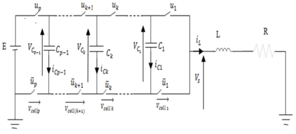
The field of power electronics has seen some important developments in the last two decades. The design and manu-facturing process of power components has improved drastically, allowing for new structures for energy conversion to be possible. The approach of multicell structures is relatively new. The idea was introduced in the 1990s [1, 2] and it proposed a series of commutation cells linked by floating voltage sources. These floating voltage sources are implemented by using capacitors. In this way, we can have N voltage levels with p = N− 1 commutation cells (Fig. 1). The floating voltage sources set a voltage drop for each cell equal to Ep, while the value of the current through the switches is identical with that of a classical structure [3]. Because of the use of capacitors as floating voltage sources, the voltage across them must be balanced within a certain interval around the desired value of Ep. The ideal way to do this is without any sensors to measure the capacitor voltages. So we need to be able to determine the capacitor voltages only by measuring the output current of the system [4, 5].
The research in this area offers a wide variety of approaches. The aim of this paper is to propose two control strategies for multicellular converters. The first control law is a sliding mode control. The second control law is a Petri nets control which deals directly with the nonlinear multicellular model. The performance of these controls are demonstrated for a two cell chopper connected to a nonlinear load.
The paper is organized as follows: Section II, the multicellular chopper modeling and analysis of a switching cell are presented. In Section III the direct control based on sliding mode techniques is presented. This methods is allows to the two cells chopper associated to a nonlinear load. Section IV is devoted to the Petri net control of the converter. To illustrate the theoretical results, simulation results are presented in Section V. Finally, a conclusion will be presented in Section VI.
2
Description of the multicellular converter
The multicellular converter is a variable structure system whose configuration changes during operation. The multicellular converter consists of cells (Fig. 1). Each cell contains two complementary power electronics components and it can be
∗Corresponding author. E-mail address: [email protected]
Copyright c⃝World Academic Press, World Academic Union IJNS.2018.04.15/995
68 International Journal of Nonlinear Science, Vol.25(2018), No.2, pp. 67-75
controlled by a binary switch uk. This signal ukis equal to 1 when the upper switch of the cell is conducting and 0 when
the lower complementary switch of the cell is conducting. These cells are associated in series with R, L load and separated by capacities that can be considered as continuous sources to these cells. The converter has p− 1 floating voltage sources. In order to ensure a normal functioning, it is necessary to guaranty a regulated distribution of the voltages vCk to their
equilibrium values that equal to kEp [6].
Figure 1: P-cells chopper connected to RL load
The output voltage Vspossesses p voltage levels (0,Ep,
(p−1)
p , E) [7]. The model of this system can be obtained and
represented by p differential equations (system 1) giving its state space representation with floating voltages vCkand load
current iLas state variables.
dvC1 dt = u2−u1 C1 iL dvC2 dt = u3−u2 C2 iL · · · dvCp−1 dt = up−up−1 Cp−1 iL diL dt = u1−u2 L vC1+ u2−u3 L vC2+ ... +up−1−upL vCp−1+upLE−RLiL (1)
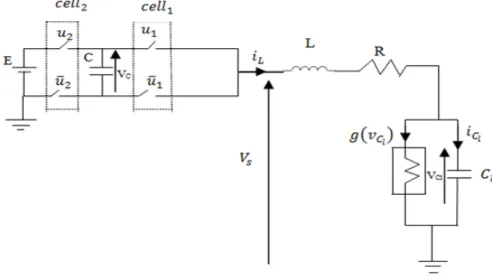
To simplify the study and the notations, we will study the overlapping operation of a converter with two cells (Fig. 2). Its function is to supply a passive load (RL) in series with another nonlinear load connected in parallel with a capacitor [8].
Four operating modes are then possible as shown in Fig. 3. Note that the floating source takes part in the evolution of the dynamics of the system only to the third and fourth mode. In the third mode, the capacity discharges and charge during the fourth mode. Thus, if these two modes last same time with a constant charging current, then the average power transmitted by this floating source over one period of commutation is null. We also notice that these two modes make it possible to obtain by commuting the additional level E
2 on the output voltage Vs.
As the switches of each cell are regarded as ideals, their behavior can be modeled by a discrete state taking of the values 0 (on) or 1 (off). In practice, some of these states never will be visited for reasons of safety measures or following the strategy of order adopted or because of the structure of the converter him finally to even or comply with the rule of adjacency. The transitions are not necessarily controlled.
The system model can be represented by three differential equations giving its state space.
Figure 2: Two-cells chopper connected to a nonlinear load LdiLdt = (u1− u2)vC− vCl− RiL+ u2E CdvCdt = (u2− u1)iL Cl dvCl dt = iL− g(vCl) (2) where g(vCl) = GbvCl+ 1
2(Ga−Gb)(|vCl+ 1|−|vCl−1|), which is the mathematical representation of the characteristic
curve of nonlinear load.
The slopes of the inner and outer regions are Gaand Gb.
70 International Journal of Nonlinear Science, Vol.25(2018), No.2, pp. 67-75
3
Sliding Modes Control Law Synthesis
Sliding mode control is a nonlinear control technique based on variable structure theory. It is very simple to complement and gives the controlled system robustness and good dynamical response [9–14]. Sliding mode control become more and more attractive to control for multi-cell converter [14]. For this study, we propose to generalize this control approach to p cells multicellular converter. Thus, we define p sliding surfaces as follows (system 4):
S1 = iLrefvC1− iLvCref 1 S2 = iLrefvC2− iLvCref 2 · · ·
Sp = iLref(E− vC1) + iLref(E− vC 2) + ... + iLref(E− vC p−1)
−iL(vC ref 1+ vC ref 2+ ... + vC ref p−1)
(3)
where e = (iLref − iL, vC ref 1− vC 1, vC ref 2− vC 2, ..., vC ref p−1− vC p−1).
The tracking error is asymptotically stable. First, we define the control objective which to satisfy the sliding surfaces S as
follow (system 5): S1 = 0 S2 = 0 · · · Sp = 0 (4)
And we use the vref k= kEp. Next, we get
S1 = iLrefvC 1− iLvC ref 1= 0 S2 = iLrefvC 2− iLvC ref 2= 0 · · ·
Sp = iLref(E− vC 1) + iLref(E− vC 2) + ... + iLref(E− vC p−1)
−iL(vC ref 1+ vC ref 2+ ... + vC ref p−1) = 0
(5) We deduce: vC 1 = vC ref 1 vC 2 = vC ref 2 · · · iL = iLref (6)
The closed loop control sequences are defined as:
ui=
1
2[1− sign(Si)], (7)
for i∈ {1, 2, ..., p}. The proposed control approach is based on the use of model developed in [15], to control two C cells converter connected to a nonlinear load.
In order to illustrate the performance of the proposed control, we considered a two C cell converter connected to a nonlinear load. Sliding modes are obviously adopted as the two C cells converter has at least one discrete control variable. Indeed, the converter switches are binary controlled (0 or 1) [13, 16, 17]. Let vC ref and iLref be the desired references
of the output voltage and the load current, respectively. Let us define the tracking error
∆xT = [vC− vC refiL− vLref], (8)
where vC ref = E2 satisfies the natural balancing. Consider the following control sequences in closed-loop for the two C
cells converter
ui=
1
2[1− sign(Si)], (9)
with i∈ {1, 2}. where the sliding mode surfaces are given by S1 = iLrefvC− iLvC ref S2 = iLref(E− vC)− iLvC ref (10)
Then, the tracking error ∆x is asymptotically stable. Let us first show that the control objective is satisfied on the sliding
surfaces S. If S1 = 0 S2 = 0 (11)
and using vC ref =E2 then we get,
iLrefvC− iLvC ref = 0 iLref(E− vC)− iLvC ref = 0 (12) then vC = vC ref iL = iLref (13)
This is the proof that the surfaces S1and S2are attractive and invariant. The control aim is to make the switching surfaces
converging to the origin, which therefore allow the state variables reaching their references.
4
Hybrid control of serial multicellular converter based on Petri nets
Dynamical systems are usually continuous or discrete or both. Continuous Dynamical Systems (CDS) have variables whose behavior continuous in time (voltage, current, speed, torque ....). They are often modeled by differential equations or transfer functions. For discrete dynamical systems (DDS), the state space is a discrete set of Boolean value [18]. Systems including both continuous and discrete state are called hybrid dynamic systems. In a very simplified one, SDH has two sub sets, a continuous block and a discrete block:
The continuous block is the dynamic evolution of the state continues, in our case the RL connection
The block has the discrete system is discrete event receives internal events, external conditions
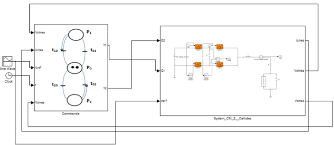
In this work, we were interested in modeling method and control systems hybrid event-based dominant the use of Petri nets [19]. The method is illustrated in Figure 4 The control consists of two parts, a continuous and a discrete. The first is based on a classical PI control loop for regulating the output voltage. This loop has as input the error E1= vC ref − vC
and iLref as output a current. The second control loop is done by a Petri net whose mission is the current regulation IS to
value iLref calculated by the PI. The current regulation is followed by a voltage balancing to ensure a better distribution
of the latter in each cell. Fig. 5 represents the Petri net control of the switches, the places P1 and P2respectively are
modeling the state of the switches of cells Cell1, and Cell2. This algorithm is developed in order to control the system, in
case it has an imbalance in the voltage of cells. The transition from one place to another is dependent on the voltage state (Table 3), current iLref and chopper configurations. The closure of the switch of the cell (Celli) depends on the validation
of the transition ti0and the elapsed delay di. This delay models the time allowed between two successive commutations, it
is based on the technology used for making the switch. For our work we took the same delay ie d = d1= d2. In the Petri
the role of two arcs inhibitors, is to prevent the presence of more than one, token in places P1and P2. The significance of
all places and transition is shown in Table 1 and 2. The imbalance of the cells voltage is one of the major problems of this type of converter, the de-balancing causes a failure of the voltage source if the string current exceeds the current permitted entry. Pollution of the power system harmonics reactions is one of the other consequences of this problem; we will show in the simulation result the contribution of our approach. Most of the converter uses PWM control multiple model for regulating voltage or current, in this work a comparison is made between sliding mode control and Petri nets control.
72 International Journal of Nonlinear Science, Vol.25(2018), No.2, pp. 67-75
Figure 4: Global structure of the Petri net control
Figure 5: Petri net control switches of the converter
Table 1: Signification of places Places Pi Designations
P0 Initial state
P1 The switch of the first cell
P2 The switch of the second cell
5
Simulation results
The simulation results are obtained using the parameters of converter as follows: L = 50mH, C = 0.1µF, Cl =
40µF, R = 10Ω, E = 100V, f = 40KHz.
Table 2: The transitions Transitions Designations t01 (e≥ +δ) or ((−δ < e < +δ) and (vC> E2)) t02 (e≥ +δ) or ((−δ < e < +δ) and (vC< E2)) t10 (e≤ −δ) or ((−δ < e < +δ) and (vC< E2)) t20 (e≤ −δ) or ((−δ < e < +δ) and (vC> E2))
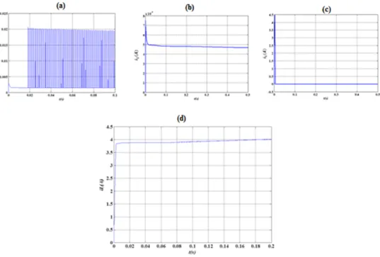
In Petri nets control, PI controller should be redesigned until the stability as well as the dynamic responses satisfy the requirements. But with sliding mode control, PI controller is not required so the design of the closed loop is greatly simplified. Then the floating voltage of the two cells chopper associated to a nonlinear load using sliding mode control and Petri nets techniques are shown in Fig. 6. Figure 7 shows respectively a simulation of the evolution of the load
Figure 6: Floating voltage vCevolutions: (a): sliding mode control; (b): Petri nets control
Figure 7: Load current evolutions: (a), (b), (c): sliding mode control ((a): u1= 1 and u2= 0 or u1= 0 and u2= 1; (b):
74 International Journal of Nonlinear Science, Vol.25(2018), No.2, pp. 67-75
currents in the (two cases) control, sliding mode control and Petri nets.
As a comparison between the sliding mode control and the Petri nets controls, we can see that the transient response duration obtained by application of the Petri nets control is less than the one obtained by sliding mode control.
6
Conclusions
In this paper, two closed loop control strategies are proposed for a multicellular converter. This kind of converter is more and more used for several industrial applications thanks to its simple architecture. The first proposed control is based on a sliding mode control which is adequate for switching converters. The design of the sliding mode control is based directly on the nonlinear studied converter model. The simulation results prove the efficiency and the robustness of the designed sliding mode control. The second proposed control is based on a Petri nets. This method is based on the statements of floating voltages, the voltage and current reference calculated by the PI and the authorized configurations. Finally simulation results show the convergence of the floating voltage and load current to a neighborhood of the value of the nominal operating voltage and current response times over. As a comparison between the two proposed controls, we can notice that the transient response duration obtained by application of the Petri nets control is less than the one obtained by sliding mode control.
References
[1] T. Meynard and H. Foch. Dispositif de conversion denergie electrique semiconducteur. brevet francais no. 91,09582,
Europe, Japan, USA, Canada, 92,00652.
[2] G. Gateau, T. Meynard, L. Delmas and H. Foch. Solitons, Stacked Multi-cell converter: topology and control. EPE Journal. 12(2)(2001), pp: 14–18.
[3] K. Benmansour. Ralisation d’un banc dessai pour la Commande et l’Observation des Convertisseurs Multicellulaires S´erie: Approche Hybride. PhD Thesis, ENSEA, 2009.
[4] G. Gateau and all. Multicell Converters: Active Control and Observation of Flying Capacitor Voltages. IEEE
Transactions on Industrial Electronics, 49(2)(2002), pp: 998–1008.
[5] F. J. Bejarno, M. Ghanes, J. P. Barbot. Observability and observer design for hybrid multicell choppers. International
Journal of Control, 83(2010) pp: 617–632.
[6] O. Bethoux, J. P. Barbot, M. Hilairet. Multicell actuator based on a sliding mode control. European Physical Journal
- Applied Physics, 43(2008) pp: 217–223.
[7] K. Benmansour, A. Benalia, M. Djemai, J. De Leon. Hybrid control of a multicellular converter. Nonlinear Analysis:
Hybrid Systems, 1(1)(2007) pp: 16–19.
[8] C. K. Tse. Complex behavior of switching power converter. CRC Press, (2003).
[9] V. J. Sivanagappa, R. Ranjani, R. Suganya, K. Sumath, R. Yamuna. Voltage Control of AC-DC Converter Using Sliding Mode Control. International Journal of Emerging Technology and Advanced Engineering, ISSN 2250-2459, 3(4), April 2013.
[10] M. Djemai, K. Busawon, K. Benmansour, A. Marouf. High order sliding mode control of a DC motor drive via a switched controlled multi-cellular converter. International Journal of Systems Science, Special Issue on VSS methods
for hybrid systems.
[11] C. F. Bogdan, D. A. Stoichescu, A. Spataru. a direct control method for multicellular converters. U.P.B. Sci. Bull.,
Series C, ISSN 1454-234x, 74(3), 2012.
[12] H. Guldemir. Study of Sliding Mode Control of DC-DC Buck Converter. Energy and Power Engineering, (3), 2011, pp: 401–406.
[13] M. Benmiloud, A. Benalia, and M. Djemai. Hybrid Sliding Mode Control for Two Cells Converter. 13th IEEE
Workshop on Variable Structure Systems, VSS14, June 29 -July 2, 2014, Nantes, France.
[14] L. Amet, M. Ghanes, and J. P. Barbot. Direct control based on sliding mode techniques for multicell serial Chopper.
2011 American Control Conference on O’Farrell Street, San Francisco, CA, USA, June 29 - July 01, 2011.
[15] D. Patino, P. Riedinger, and C. Iung. Predictive control approach for multicellular converters. in Proceedings of the
2008 IEEE IECON, pp: 3309–3314, November 2008.
[16] M. Ghanes, F. Bejarano, and J. P. Barbot. On sliding mode and adaptive observers design for multicell converter. in
Proceedings of the 2009 IEEE ACC, pp: 2134–2139, June 2009.
[17] A. M. Lienhardt, G. Gateau, and T. Meynard. Digital sliding-mode observer implementation using FPGA. IEEE
Trans. Industrial Electronics, 54(4), pp: 1865–1875, August 2007.
[18] R. Goedel, J. Hespanha, A. R. Teel, C. Cai, and R. Sanfelice. Hybrid systems: generalized solutions and robust stability. Proceedings of IFAC, Nolcos, 2004.
[19] S. Lafortune, G. Cassandra. Introduction to discrete event systems. Published in september 1999 by Kuwer Academic