POWER PROCESSING UNIT ACTIVITIES
AT THALES ALENIA SPACE BELGIUM (ETCA)
SPACE PROPULSION 2016
MARRIOTT PARK HOTEL, ROME, ITALY / 2–6 MAY 2016
Eric Bourguignon(1), Stéphane Fraselle(2), Thierry Scalais(3), Jean-Marc Defise(4)
(1)(2)(3)(4)
Thales Alenia Space Belgium, B-6032, Mont-sur-Marchienne, Belgium, [email protected]
KEYWORDS : PPU, ETSU, FU, Hall Effect Thruster ABSTRACT:
Since 1996, Thales Alenia Space Belgium (ETCA) designs, develops and produces Power Processing Unit (PPU) to supply Hall Effect Thrusters.
The first qualification model, developed for the 50V bus Stentor program, has supplied during 8900 hours an SPT-100 thruster in a vacuum chamber simulating space environment. Qualified for the 100V Spacebus 4000 platform, the 100V PPU and Filter Unit (FU) EQM have cumulated 6300 hours ground operation with a PPS1350-G thruster. Thirty-three PPU Mk1 flight models were delivered for the Stentor, SES, Smart-1, Intelsat, Inmarsat, Eutelsat, AlphaSat, Yahsat, Direct-TV, SkyBrasil, SmallGEO and Amos satellites. In October 2005, the Smart-1 spacecraft reached the Moon after 4958 hours of cumulated operation of the PPU and its PPS1350-G thruster. Eighteen PPU’s currently in flight for North South Station Keeping on nine telecom satellites have cumulated more than 32 400 hours flight operation in March 2016.
For the SmallGEO platform, TAS-B has developed and qualified an External Thruster Selection Unit (ETSU) to select one out of four thrusters. Two ETSU flight models were delivered, associated with the PPU flight models.
In order to propose a more competitive product, TAS-B has developed and qualified, for the 100V bus platforms, the PPU Mk2, dedicated to Hall Effect Thrusters up to 2.5kW. The PPU Mk2 EQM was successfully coupled with the SPT-100, PPS1350-G at 1.5kW and PPS1350-E at 2.5kW. The production of eight ordered PPU Mk2 flight models is on-going; the first model is delivered.
To reply to the market demand to use Electrical Propulsion for Orbit Raising, TAS-B has developed and qualified in March 2016 the PPU Mk3 dedicated to 5kW Hall Effect Thrusters. The PPU Mk3 is based on the PPU Mk2 heritage but features additional optimizations to reduce cost. The PPU Mk3 development is consolidated by successful coupling
The first PPU Mk3 flight models are already ordered for delivery in 2016.
In order to prepare the next PPU generation, innovative topologies and new components are being investigated in order to propose more flexible and more competitive PPU.
This paper presents an overview of the Power Processing Unit activities at TAS B.
NOMENCLATURE
EPS = Electric Propulsion System
EPTA = Electric Propulsion Thruster Assembly ETSU = External Thruster Selection Unit FU = Filter Unit
HET = Hall Effect Thruster
HEMPT = Highly Efficient Multistage Plasma T. GIE = Gridded Ion Thruster
PPU = Power Processing Unit SPT = Stationary Plasma Thruster TSU = Thruster Selection Unit XFC = Xenon Flow Controller
1. PPU MAIN FUNCTIONS
The PPU is composed of the following modules (see Fig. 1):
♦ Interface on the Primary input power bus, insures main bus protection, voltage level conversion and galvanic isolation required by the SPT supplies.
♦ SPT power supplies, the 4 types of electrodes of the Stationary Plasma Thruster (anode, magnet, heater, ignitor) are supplied according to their specific power profile.
♦ XFC power supplies, PPU supplies the Xenon Flow Controller: opens or closes the xenon valves and controls the discharge current by the regulation of the xenon flow via the thermothrottle power supply.
♦ Sequencer, insures the automatic control and the survey of the thruster operation: start-up, stop, regulated thrust, failure recovery, ...
ANODE V A & I A REGULATOR MAGNET IM REGULATOR HEATER IH REGULATOR IGNITOR PULSE REGULATORS I TT REGULATORS VALVES DRIVERS THRUSTER ANODE MAGNET HEATERS IGNITORS THERMO-THROTTLES VALVES INVERTERS INPUT LIMITER DC/DC CONVERTER TC/TM INTERFACE SEQUENCER TC/TM BUS (N) (R) PRIMARY INPUT BUS PRIMARY INPUT BUS ON/OFF TC S P A C E C R A F T I N T E R F A C E XFC
Figure 1. PPU functional block architecture
2. PPU MK1
The main characteristics of our current PPU Mk1 product are summarised hereunder:
♦ Dedicated to SPT-100 and PPS1350-G Hall Effect Thrusters.
♦ Compatible with 50V or 100V regulated input power bus.
♦ Maximum Anode Power : 1500 W.
♦ Includes SPT and XFC power supplies.
♦ TC/TM plug-in module available for MIL-STD-1553, ML16-DS16 and OBDH-RS485 (RUBI) communication busses.
♦ Can be equipped with or without a switching module (called TSU for Thruster Selection Unit) allowing to drive one out of two thrusters ; this module is typically used for North-South station keeping application on geo-synchronous satellite.
♦ Efficiency in nominal operating conditions:
• 91.6 % for Vbus = 50V
• 92.4% for Vbus = 100V.
♦ Mass for one PPU including TSU: 10.9 kg.
♦ Dimensions: 390x 190 x 186 mm³ (LxWxH).
♦ Fully qualified according to environment specifications of European platforms Eurostar 3000, SpaceBus 3000, SpaceBus 4000 and AlphaBus.
♦ 8 900 hours lifetime test in space vacuum conditions coupled with SPT-100 thruster.
♦ 4 958 hours flight experience on Smart-1 launched in September 2003.
♦ 32 400 hours cumulated flight operation on nine geo-synchronous telecom satellites, in March 2016.
♦ Thirty three flight models already delivered for Stentor, SES, Smart-1, Intelsat, Inmarsat, Eutelsat, AlphaSat, Yahsat, Direct-TV, Sky Brasil, SmallGEO and Amos.
♦ Components obsolescence has been handled to produce last batch of PPU Mk1 50Vbus; the 100Vbus version of PPU Mk1 is replaced by the PPU Mk2.
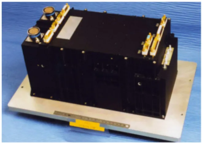
Figure 2. Stentor PPU EQM
3. FU
In a standard EPS configuration, a Filter Unit (FU) is used between the PPU and each thruster. The aim of the FU is to
♦ provide filtering on the thruster lines, the thrusters behaving as noise generators at high frequencies;
♦ provide stabilization of the anode discharge current in order to avoid degradation of thruster efficiency with quasi-periodic oscillations in the 10-50 kHz range;
♦ limit the radiated emission inside the spacecraft;
♦ limit the conducted susceptibility at PPU level. To achieve these functions, a passive filtering unit has been designed.
The 1.5 kW version of the FU was fully qualified through an EQM programme followed by a PFM. It has been validated with PPU Mk1 and was used for coupling tests with SPT-100 and PPS1350-G thrusters.
TAS-B provided the FU's for SES, AlphaSat and Amos.
Figure 3. FU
4. PPU SMALLGEO
4.1. PPU SmallGEO Introduction
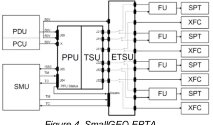
The Electric Propulsion System (EPS) of the new small geostationary satellite platform “SmallGEO” is based on two redundant Electric Propulsion Thruster Assembly (EPTA) branches (see Fig. 4). Each EPTA branches includes one PPU driving one out of four thrusters. As the TAS-B PPU includes one Thruster Selection Unit (TSU) module performing a 1:2 selection, a new equipment, the External Thruster Selection Unit (ETSU), is developed to be connected in series with PPU output terminals and to perform a 2:4 selection. The configuration with 2 equipments (PPU + ETSU) was preferred to benefit from PPU flight heritage without major PPU mechanical modification to implement additional modules to perform the 2:4 selection.
Figure 4. SmallGEO EPTA
The ETSU equipment has been qualified. Two flight sets (PPU+ETSU) were delivered for SmallGEO
4.2. PPU SmallGEO Description
The PPU SmallGEO is a modified PPU Mk1 to insure compatibility with the requirement of 1.5kW maximum consumption on SmallGEO power bus.
4.3. ETSU Description
The External Thruster Selection Unit is composed of 2 modules (see Fig. 5). As the TSU module integrated in the PPU, each ETSU module includes electro-mechanical latching relays and their drivers to switch PPU SPT and XFC lines to one out of two ways. The ETSU also includes :
♦ Auxiliary Power Supply to directly supply the relay drivers,
♦ TC/TM interface to activate ETSU and perform selection.
♦ Discharge networks connecting floating electrodes of the thruster to ETSU structure. These resistances draw the electrons captured by the thruster electrodes (and their wiring harness) to the satellite electrical ground.
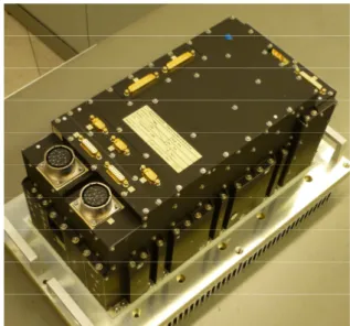
Figure 5. ETSU
5. PPU MK2
5.1. PPU Mk2 Development
In the frame of AlphaBus extension program and in partnership with the Primes, TAS-B has developed an optimized and more competitive product: the PPU Mk2. The PPU Mk2 addresses Hall Effect Thrusters up to 2.5kW and is dedicated to AlphaBus, Eurostar 3000, SpaceBus 4000 platforms. Taking benefit of flight experience, the PPU Mk2 provides 1.6 times more output power (1.5kW 2.5kW) and more flexibility to thrusters and platforms, with reduced manufacturing cost.
5.2. PPU Mk2 Objectives
PPU Mk2 objectives are:
♦ More competitive product
♦ Replacement of obsolete parts
♦ Compliance to current Primes AD’s and ECSS rules
♦ Dedicated to Hall Effect Thrusters up to 2.5kW: SPT-100, PPS1350-G, PPS1350-E.
♦ Common design and hardware for AlphaBus, SpaceBus 4000, Eurostar 3000 platforms:
• Bus voltage: 100V regulated
• MIL-STD-1553B interface
5.3. PPU Mk2 Description
PPU Mk2 features are:
♦ Anode output characteristic is commandable in the range 220V – 350V, with short-circuit current commandable in the range 5A – 11A, see Fig 6 .
Figure 6. Anode output characteristic
♦ Thruster type may be defined after PPU manufacturing, via external configuration straps.
♦ Standard start-up or low power/low voltage start-up to reduce inrush current may be selected.
♦ PPU is robust to abnormal pressure increased inside satellite up to 1Pa, by mechanical architecture.
♦ Sequencer based on a FPGA provides more flexibility. By telecommand, the defaults values and major parameters are adjustable, the protections may be inhibited.
♦ Optional magnet trim supply.
♦ PPU Mk2 is composed of 6 modules:
• Primary: input switch for bus protection and DC/DC to supply the low-level
• Anode supply
• Heater and Ignitor supplies
• Thermothrottle and Magnet supplies
• TSU and Valve Driver
• Sequencer
♦ Same baseplate size (390mm x 190mm) and fixation holes as current PPU Mk1, see Fig. 7.
Figure 7. PPU Mk2
5.4. PPU Mk2 Qualification
A Qualification Model was built and tested. Figure 8 shows the efficiency measurements obtained on the Qualification Model in function of the discharge supply output power at a voltage of 350V with the valve driver and the thermothrottle supply active: above 94.4% up to 2.68kW. 94.2 94.4 94.6 94.8 95 95.2 95.4 95.6 95.8 1500 1700 1900 2100 2300 2500 2700 E ff ic ie n cy [ % ]
Discharge supply output power [W]
PPU Mk2 EQM efficiency in function of discharge output power
25°C baseplate -25°C baseplate 70°C baseplate
Figure 8 : EQM efficiency at 350V
Similarly to PPU Mk1, the PPU Mk2 presents a defined voltage-current slope above the knee current to enable the thruster start-up without risking a locking point at low voltage due to the thruster characteristic. Figure 9 shows the voltage-current characteristic measured on the PPU Mk2 with the anode voltage set at 300V and the knee-current at 5A.
0 50 100 150 200 250 300 350 0 1 2 3 4 5 6 7 8 9
Discharge current [A]
A n o d e v o lt a g e [ V ]
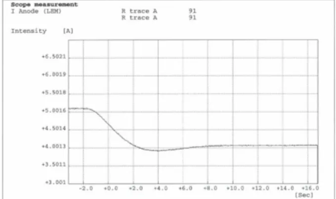
Figure 9 : Anode voltage-current characteristic (voltage setting at 300V and knee-current at 5A) Thruster start-ups were recorded on the Demonstrator Model using a representative thruster simulator based on initially discharged capacitors. Figure 10 presents the output voltage, output and input current during a thruster start-up. During this test, the discharge voltage was set at 300V before the thruster start-up occurred and the knee-current was set at 5.5A. The thruster load after start-up is 5A imposed by a resistive load.
Figure 10 : Thruster start-up
It may be seen that during the thruster start-up test, the discharge voltage initially drops because the thruster consumption is higher than the knee-current. The discharge voltage then recovers its setting value as the discharge current diminishes after the start-up. The discharge current is reflected on the primary bus consumption through the PPU transformer scaling and its power filters. The knee-current setting enables to modify the peak input-current because it changes the peak power output of the PPU.
The PPU Mk2 provides a numerical proportional-integral regulation of the discharge current by acting on the thermothrottle current. This regulation enables to control the thrust despite the pressure perturbations upstream the thermothrottle. The effectiveness of the regulation has been validated with a simulator of the worst-case thermothrottle current to discharge current transfer-function.
Figure 11 presents a step response recorded with the PPU Mk2 coupled to the transfer function simulator when the discharge current setting is changed from 5A to 4A. Tests were also performed where a perturbation (sine and triangular) is injected in the transfer-function simulator. The perturbation rejection performance has been measured and is in line with the analysis.
Figure 11 : Discharge current step change response
After the PPU Mk2 mechanical qualification, including vibration and pyro-shock test, the thermal vacuum qualification tests were concluded by a pressure increase test up to 2Pa to demonstrate PPU robustness to abnormal pressure increase inside satellite. The thermal vacuum campaign has been followed by a complete EMC test campaign including different LISN configurations to cover the SB4000, E3000 and Alphabus platforms. The Qualification Review was successfully held in July 2014.
5.5. PPU Mk2 Coupling Tests
In July 2014, after the Qualification Review, the PPU Mk2 EQM was coupled with a SPT-100 thruster in the Pivoine facility at CNRS Orléans, France.
In October 2014, the PPU Mk2 EQM and FU EQM were coupled with a PPS1350 thruster, in the Snecma facilities at Vernon, France. Three operating points (250V/4.28A, 350V/4.28A and 350V/7A) were characterized. Two harness lengths were tested and no modification of the thruster performances was observed. The PPU Mk2 soft start mode to ignite the thruster was also validated. This mode reduces significantly the PPU inrush current at thruster ignition. Firings at maximum power (2.5 kW) were performed during 3 hours. They have demonstrated good thermal behaviour of the PPU Mk2 and the FU.
In February 2016, the PPU Mk2 EQM and FU EQM were coupled with a SPT-100 thruster, in the Fakel facilities at Kaliningrad, Russia. Detailed characterisation of the 300V/4.5A operating point was performed.
5.6. PPU Mk2 Flight Models Status
The production of eight ordered PPU Mk2 flight models is on-going; the first model is delivered.
6. PPU MK3
6.1. PPU Mk3 Introduction
To reply to the market demand to use Electrical Propulsion for Orbit Raising, TAS-B has developed and qualified in March 2016 the PPU Mk3 dedicated to 5kW Hall Effect Thrusters. The PPU Mk3 is based on the PPU Mk2 heritage but features additional optimizations to reduce cost. PPU Mk3 objectives are:
♦ Competitive product,
♦ Dedicated to SPT140-D, PPS-5000 and XR-5 thrusters.
♦ Dedicated to SpaceBus Neo, Eurostar 3000, NeoSat and Electra platforms.
• Bus voltage: 100V regulated
• MIL-STD-1553B interface
6.2. PPU Mk3 Description
PPU Mk3 features are:
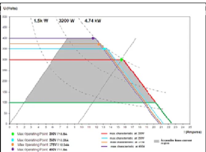
♦ Anode supply output characteristic is commandable in the range 100V – 400V, with short-circuit current commandable up to 22A. As presented on Fig.12., the anode supply, based on two modules of 2.5kW connected in parallel, delivers up to 4.74 kW.
Figure 12: U-I characteristics of the Anode Supply
♦ Magnet supply drives the thruster magnet coils independent from the discharge, with current up to 7A.
♦ Heater supply current capacity is increased up to 18A.
♦ Two Filter Units are implemented inside PPU Mk3, downstream the TSU.
♦ Standard start-up or low power/low voltage start-up to reduce inrush current may be selected
♦ PPU is robust to abnormal pressure increased inside satellite up to 1Pa, by mechanical architecture.
♦ Sequencer based on a FPGA provides more flexibility. By telecommand, the defaults values and major parameters are adjustable, the protections may be inhibited.
♦ Mass of PPU Mk3 with TSU + 2FUs: 18.6 kg.
♦ Dimensions: 390x 315 x 263 mm³ (LxWxH).
6.3. PPU Mk3 Development
The PPU Mk3 development started in 2013, with a Study Phase, to issue and review PPU Mk3 specification with the thruster manufacturers and the primes. The PPU Mk3 architecture was optimized and new packaging was selected to reduce the number of modules and sub-assemblies in order to propose more competitive product. This phase was concluded in January 2014 with the issue of the Technical Requirement Document which is the input for the following phase, the PPU Mk3 Development Phase.
During this phase, a 5kW anode and FU breadboard were coupled with a SPT140-D thruster, in Fakel facilities, at Kaliningrad, Russia, in October 2014, in order to secure the interfaces with the thruster. By powering the thruster up to 400V and 4.7kW, the anode supply output characteristics and output impedance were validated. The implementation of the FU inside the PPU Mk3 was also validated by testing different harness lengths between PPU, FU and thruster. With these results, the PDR was successfully closed in November 2014.
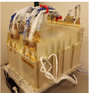
The PPU Mk3 Demonstration Model (Fig 13.), representative of future flight model (fit, form and function) was developed, manufactured and tested with representative load simulating the thruster, including hot and cold characterization.
Figure 13: PPU Mk3 DM
Figure 14 shows the evolution of PPU Mk3 efficiency, typically above 95%, with the output power and voltage. The measurements at 3 temperatures are above 94.7% up to 4.7kW. The PPU Mk3 DM was also tested up to 5.2kW in order to demonstrate
10% margin on the maximum output power.
Figure 14 : PPU Mk3 efficiency
6.4. PPU Mk3 Coupling Tests
In May 2015, the PPU Mk3 DM has been successfully coupled with a SPT140-D thruster at Aerospazio facilities, in Italy. The coupling test results have supported the CDR closed in September 2015.
In October 2015, the PPU Mk3 DM was also successfully coupled with a PPS-5000 thruster at Pivoine facilities in CNRS Orléans, France.
In December 2015, the PPU Mk3 DM was also successfully coupled to an XR-5 thruster (without XFC) in the frame of an ESA contract led by European Space Propulsion (ESP) as well, at QinetiQ facilities in Farnborough, UK. This test involved experts from ESP, Aerojet Rocketdyne, TAS-B and Mars-Space.
6.5. PPU Mk3 Qualification
Figure 15 shows the PPU Mk3 Qualification Model:
Figure 15 : PPU Mk3 EQM
After its mechanical qualification, including vibration and pyro-shock test, the thermal vacuum qualification tests were concluded by a pressure increase test up to 2Pa to demonstrate PPU Mk3 robustness to abnormal pressure increase inside satellite. The thermal vacuum campaign has been followed by a complete EMC test campaign including different LISN configurations to cover the E3000 and SpacebusNeo platforms. The Qualification Review was successfully held in March 2016.
6.6. PPU Mk3 Flight Models Status
Twelve PPU Mk3 flight models are already ordered by two European Primes with first deliveries in 2016.
6.7. PPU Mk3 variant for XR-5
Similarly to PPU Mk1 and Mk2, the PPU Mk3 supplies the thermothrottle of the Xenon Flow Controller to adjust the thruster xenon flow. The thruster discharge is regulated by the PPU sequencer through control of the thermothrottle supply. As the XR-5 thruster is currently qualified with proportional valves (PFCV) instead of thermothrottle to adjust the xenon flow, TAS-B has performed, with ESP, a Neosat pre-development activity to validate TAS-B PPU Mk3 capacity to supply and regulate a Proportional Valve. TAS-B has developed and manufactured a breadboard model, that was coupled to a PFCV in November 2015 at ESP/TAS-UK facilities in Belfast, UK. The test setup included a Thruster simulator reproducing the Discharge current, allowing to test the Discharge current regulation control through the PFCV. The coupling test was successfully carried out. The digital model used for regulation study and optimization was thereby validated. The Discharge current stability, accuracy, response time and overshoot were within required performances. Thanks to this pre-development and the coupling test of PPU Mk3 DM with XR-5 thruster, the development of a PPU Mk3 variant for XR-5 thruster is secured.
7. R&I ACTIVITIES
TAS-B has been granted of two ARTES-5.1 ESA contracts allowing TAS-B to prepare the next generation of PPU :
♦ Configurable High Voltage Power Supplies (CHVPS) for Full Electric Propulsion Spacecraft.
♦ High Voltage Switching Matrix for new generation of Full Electric propulsion applications in Telecom.
In the frame of CHVPS project, TAS-B designs and develops a flexible 5kW high voltage power supply for electric thrusters: HET, HEMPT and GIE. After the trade-off phase, including new topology concept selection and the design phase, the breadboard is now being manufactured. It is a single power converter delivering up to 5kW / 2 kV thanks to a new topology concept. This breadboard also includes new technologies to improve the power density leading to implementation cost reductions.
In the frame of High Voltage Switching Matrix, TAS-B performs trade-off to implement an efficient (low voltage drop) and competitive thruster switching unit capable of withstanding high voltages and high currents. All possible solutions are being analyzed such as semi-conductors, relays or other switching mechanisms in order to determine the most effective and competitive solution. The outcome will be a tested breadboard.
8. CONCLUSION
Up to now, 34 PPU flight models have been delivered and 21 PPU flight models are in production phases for our direct customers: Airbus DS, IAI, Snecma, TAS-F for Amos, CNES, DirecTV, Eutelsat, ESA, Inmarsat, Intelsat, OHB, SES, Sky Brazil and Yahsat.
These orders demonstrate the confidence of Primes and customers in TAS-B experience in Electric Propulsion, based on:
♦ 8 900 hrs ground coupling test with EQM Stentor
♦ 6 400 hrs ground coupling test with EQM SB4000
♦ 4 958 hrs flight operation of SMART-1
♦ 32 400 hrs in orbit on telecom satellites
TAS-B has acquired a solid experience and a very good knowledge of the electrical interfaces between thruster and PPU confirmed by the success of numerous integration tests with SPT-100, SPT140-D, PPS1350-G, PPS1350-E, PPS-X000, RIT-22, HEMPT, PPS-5000, XR-5 thrusters.
The successful PPU Mk3 QR consolidates the delivery of PPU Mk3 flight models in 2016.