PROCEEDINGS OF SPIE
SPIEDigitalLibrary.org/conference-proceedings-of-spie
Preliminary design of SALTO: the
Belgian adaptive optics demonstrator
G. Orban de Xivry, O. Absil, M. Lismont, V. Moreau, F.
Languy, et al.
G. Orban de Xivry, O. Absil, M. Lismont, V. Moreau, F. Languy, D.
Vanhoenacker-Janvier, "Preliminary design of SALTO: the Belgian adaptive
optics demonstrator," Proc. SPIE 10703, Adaptive Optics Systems VI,
1070338 (11 July 2018); doi: 10.1117/12.2313578
Event: SPIE Astronomical Telescopes + Instrumentation, 2018, Austin, Texas,
United States
Preliminary
design of SALTO, the Belgian adaptive optics
demonstrator
G.
Orban de Xivry
a,
O. Absil
a,
M. Lismont
b,
V. Moreau
b,
F. Languy
c,
and D.
Vanhoenacker-Janvier
da
Space
sciences, Technologies, and Astrophysics Research (STAR) Institute, Universite´ de
Li`
ege,
Belgium
b
Advanced
Mechanical and Optical System (AMOS), Li`ege, Belgium
cCentre
Spatial de Li`ege (CSL), Belgium
d
Institute
of Information and Communication Technologies, Electronics and Applied
Mathematics
(ICTEAM), Universit´e catholique de Louvain, Belgium
ABSTRACT
SALTO is a Belgian project aiming to build a complete 1 m telescope demonstrator including a single-conjugated adaptive optics (AO) system together with a Rayleigh laser guide star system. The underlying objective of SALTO consists in developing the Belgian expertise regarding AO systems for medium size telescopes (i.e. diameter from 1 to 4m), for application in astronomy, optical communication or detection of low-Earth orbit objects. The project approach is to base the design on COTS components, in order to reduce complexity, and to favor both robustness and automation of the system over performance. The SALTO demonstrator will be located at Redu Space Services in the Belgian countryside. Therefore the major challenge of the project will be to deal with poor seeing, far worst than astronomical standards, while preserving robust and reasonable correction in the red-visible and near-infrared wavelength range. Here, we present our system baseline, the expected performance, and the preliminary design of the AO system. We conclude with the current prospects for the project.
Keywords: adaptive optics; Rayleigh laser guide stars; telescope demonstrator
1.
INTRODUCTION
Nowadays, adaptive optics (AO) is a scientific-driver technology in observational astronomy. Indeed, most large observatories have now at least one flavor of an AO system implemented in their ground-based telescopes. The later introduction of laser guide stars in astronomy about two decades ago has been one of the elements popularizing the use of AO in a wide field of astronomical applications.1 Nevertheless the scarcity and the complexity of large ground-based telescopes – including in particular their AO system – along with a high demand for observing time make the access to high resolution imaging capability quite limited.
With the progresses in AO technologies, most of the key elements – from fast wavefront sensor detector to laser and high-order deformable mirror – are now available commercially. Robust and affordable laser guided single conjugated AO system on medium size telescopes seems therefore within reach, giving an opportunity to upgrade the large number of 1–4 m existing telescopes.
A successful path initiated by Robo-AO relies on a robust, highly automated and easy to use system able to observe a significant fraction of extremely large surveys. Indeed large sky surveys are coming online (from Gaia to Plato, Tess, LSST, to cite a few). Those surveys necessitate efficient follow-up to confirm and characterize the large number of discoveries made. The scientific topics range from transiting exoplanets and stellar systems to extragalactic objects such as lensed quasars. This route includes large population studies, rapid target characterization and long-term monitoring.2
Further author information: (Send correspondence to G. Orban de Xivry) G. Orban de Xivry: E-mail: [email protected], Telephone: +32 4 3669712
000000000000000eCEL1
ector
Adaptive :optics
& Test -Camera r
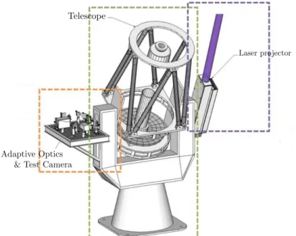
Figure 1. Sketch of the envisionned SALTO demonstrator : a 1-m class telescope with side laser launch and Nasmyth plateform for the AO system and test camera.
With Salto, we want to build a 1 m class telescope demonstrator with a laser guide star (LGS) AO in order to benchmark robust AO systems for 1–4 m telescopes. The end goal is to be able to offer affordable adaptive optics systems that are reliable and relatively easy to use in order to improve the complementarity of small versus large telescope apertures. Finally, reliable and easy to use LGS AO systems on medium size telescopes are also of interest for space debris tracking and imaging, and ground-space optical telecommunications.
In this paper, we present all the aspects of the Salto project. In Section2, we discuss the site foreseen to install the demonstrator, its constrains and our current strategy. In Section3, we present our analytical and end-to-end simulations performed to determine a few system parameters and study the robustness and performance of the AO under different conditions. In Section 4, we discuss the sub-systems of Salto, i.e. the telescope
design itself, the LGS concept, and the AO module.
2. GENERAL CONSIDERATIONS
The Salto project is a complete AO demonstrator including the telescope, the laser and the AO system as illustrated in Figure 1. It will be installed in the Belgian countryside allowing a fast track installation and commissioning. The expected poor site imposes a certain complexity of the AO system. Amongst others and despite the small size of the telescope aperture, the large seeing imposes a relatively high degree of correction similar to 2–4 m telescopes on astronomical sites.
2.1 Site
The system will be installed and operated in Redu in collaboration with Redu Space Services (RSS). The RSS center takes up 29000 m2with currently 3000 m2 occupied. RSS is expert in the installation of antennas system and operation of key satellite programs. RSS develops its activities in the fields of telecommunication, ground and space observation, and navigation.
The site is located in the Belgian countryside about 350 m high, providing relatively low light pollution and easy access. However, it is not expected to be a particularly good location for an optical telescope and we expect to deal with poor seeing and varying cloud coverage.
A crucial part of the project is first to measure the strength of the atmospheric turbulence and elaborate atmospheric forecasting tools. To do so, our current strategy is
1. Setup a differential image motion monitor (DIMM) campaign to measure the integrated seeing and help to constrain the AO design. We currently have a Celestron C14 (D = 35.6 cm) with a DIMM mask of aperture size d= 12 cm and baseline B = 25 cm. We are currently implementing a DIMM software based on a multi-threaded Python code which finds the double stars, computes the seeing, debiases the noise, and corrects the telescope pointing using the ASCOM∗ protocol. The procedure follows the recommendations from [3]. We plan to install this DIMM in the near future at Redu in order to gather seeing statistics. The DIMM is intended to stay there during the future commissioning and operation of Salto to provide external seeing telemetry measurements.
2. In parallel, we are planning to perform atmospheric turbulence forecasting. The Weather Research & Forecasting (WRF) model will be used based on European Center for Medium Weather Forecast (ECMWF) meso-scale inputs to reach an expected spatial resolution of about 1km and temporal resolution of 5 minutes. This will inform us on the Cn2 profile and forecast the atmospheric conditions. Since we will not benefit from any profiler such as a MASS or SCIDAR, it will be our sole indication in term of Cn2 profile for the Salto site.
While those tools are being implemented, we do not currently possess solid seeing measurements. Therefore, in the following system analysis, we consider seeing ranging from 2 to 3.5′′, a Hufnagel-Valley profile and a classical Bufton wind model. Cloud coverage may be an issue but since Salto serves essentially as a demonstrator rather than for any scientific application, on-sky time is not a constrain as long as the commissioning and performance tests of the demonstrator can be achieved. As such Salto will also be a good test for the practicability of such facility on a site like Redu - a possible prospect for optical telecommunication relay stations.
3. SYSTEM STUDY
3.1 Analytical Error Budget
In the framework of this study, we have developed an AO analytical error budget tool written in Python. The primary purpose of the code is to compute AO wavefront error budgets for different architectures and sciences cases. The tool includes calculation of several metrics for the achieved performance such as Strehl ratio, ensquared energy, FWHM, sky coverage and a few key system parameters.
It is subdivided in a few modules including:
• Atmospheric Quantities module which implements: modeling of the C2
n profile, the wind profile, and the computation of several relevant quantities (such as the typical Fried parameter, Greendwood frequency, etc.), and proxies for the atmospheric transmission, Rayleigh backscatter parameter, atmospheric pressure, etc.
• Error budget module which provides a set of methods to compute the different contributions to the error budget.
• A performance analyzer and pre-designer which bundles together the two previous modules, performing a global error budget and providing different system parameters relevant to the design.
In the framework of the Salto project, we use this tool to perform an initial error budget and define the optimum number of subapertures, the LGS height and the gating range. The baseline parameter for this short study are:
• Hufnagel-Valley 5/7 profile (i.e. HV with r0= 5 cm and θ0= 1.4′′) which generates a mean seeing of 2′′. • A Bufton wind model with a maximum speed of 35 m/s at 9.4 km.
• Telescope diameter of 700 mm
• altitude of the site of 359 m
• A 10W Rayleigh laser at 532 nm with a negligible tip-tilt error.
By balancing fitting and measurement errors, we selected a conservative number of 10 subapertures on the telescope diameter with 70 corrected modes. The LGS height is chosen to be at 10 km with a large gating range of 1.5 km. This ensures a relatively large number of photons of about 160 photons/frame/subaperture at 1.5 kHz and an acceptable spot elongation of maximum 2′′ with a side launch. In practice the gating range and speed may be reduced based on hardware and photon flux considerations.
Based on those parameters a preliminary analytical error budget is given here below (Tab. 1-3), including a few system parameters (Tab. 1), and some performance metric in three bands (Tab. 3) from red to near-infrared : R, H, K.
Table 1. Main general system considerations.
Values Units
Subaperture size 7 cm
Total number of subapertures 79
number of photons / frame / subap 159
High-order stroke requirement 661 nm
Tilt stroke, for optical magnification=50 346 µrad
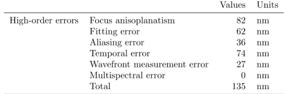
Table 2. Analytical wavefront error budget for observation at zenith. Tip-tilt errors are neglected here.
Values Units High-order errors Focus anisoplanatism 82 nm
Fitting error 62 nm
Aliasing error 36 nm
Temporal error 74 nm
Wavefront measurement error 27 nm
Multispectral error 0 nm
Total 135 nm
Table 3. Performances for three observing bands : R, H, K
Strehl FWHM EE50
R 658nm 18.0 % 0.2 arcsec 1.02 arcsec H 1630nm 76.0 % 0.48 arcsec 0.35 arcsec K 2190nm 86.0 % 0.65 arcsec 0.42 arcsec
3.2 End-to-end simulations
Beyond the analytical error budget, we identify the control basis and move to end-to-end simulations to perform the first systematic study of the performances expected with Salto.
In a first step, we compare Zernike and Karhunen-Lo`eve modes on an annular pupil and as projected on the foreseen deformable mirror (ALPAO-DM97) influence functions. Comparing the conditioning number, the fitting error and the force on the DM, we conclude that KL modes are more favorable and allow a slightly larger number of modes to be corrected (∼ 70 instead of ∼ 60 modes).
We then move to end-to-end simulation based on Soapy†, using our KL basis projected on the mirror space. As the Cn2profile is currently unknown, we consider a Hufnagel-Valley (H-V) distributed in 4 layers with a strong
ground layer consisting of about 80% of the turbulence between 0 and 500 m. This will be refined in the future using profiles generated using the WRF.
In addition to the DM influence functions, the simulations include the telescope pupil, the LGS uplink effect and the WFS noise. We explore seeing from 2.5′′to 3.5′′, and consider different scenarii :
Case 1 baseline scenario. The simulation parameters are given in Tab. 4.
Case 2 unfavorable atmospheric distribution : a stronger higher layer contribution leading to higher cone error. In this case, the ground is set to contain 50% and the 4.5 km layer 40%.
Case 3 unfavorable loop delay. This scenario is studied for the cases of sub-optimum RTC latencies and higher wind speeds. We consider a 4 frame delay instead of 2.
Case 4 unfavorable sampling : we consider a 4×4 Shack-Hartmann instead of 10×10. This scenario being studied for lower flux or degraded LGS spots conditions.
Case 5 all unfavorable cases combined.
Each simulation consists of 15 seconds or 15000 iterations. The key parameters of the simulation are given in Tab. 4.
Table 4. Parameters used for simulation of SALTO baseline.
Parameter Value
Nb of turbulent layers 4
Fried parameter at 500nm r0 [cm] 0.0404 for 2.5′′seeing Relative layer strength [0.807, 0.15, 0.04, 0.03] Layer altitude [km] [0.25, 4.67, 13, 20] Layer wind speed [m/s] [5.8, 16.3, 22.1, 5.3] Wind orientation [degree] 0 for all
Outer scale L0 for all layers [m] 20
Frame rate [Hz] 1000
Loop delay [ms] 2
Total exposure time [s] 15
Telescope diameter [m] 0.7
Central obscuration diameter [m] 0.16 Nb of subapertures on pupil diameter 10
Pixels per subaperture 8
Subap field-of-view [′′ ] 6.5-8.5 Number of Karhunen-Loeve modes 50-70 Laser guide star altitude [km] 10
Science target wavelength[µm] [0.5, 0.8, 1.55]
Zenith distance [degree] 0
The results show that, in all cases, the AO system brings an improvement in the red visible and NIR both in 50% encircled energy diameter and FWHM. This is illustrated in Figure2for the worst seeing (3.5′′). The same trends are seen in the seeing range from 2.5′′to 3.5′′. The baseline (case 1) sees a decrease in FWHM gain from 1 µm to 1.6 µm due to the small size of the telescope, as the gain reachable is biased by the diffraction limit.
Despite the poor seeing conditions considered, this short study confirms that our system should provide a stable closed-loop and a noticeable gain in performances under the different scenarii explored.
-o
o
Ir' w C-
m coSeeing of 35"
0:6 0:8 1.0 1.2 1:4 1:6 wavelength [pm]5-Seeing of 3.5"
2---- case 7.
case2-0° case 3
--- case 4 --a- case5 , 0.6 0.8 1.0 1.2 . 1:6 wavelength [Nm] Figure 2. Gain of 50% encircled energy and FWHM for a poor seeing condition of 3.5′′. The gains are given at 500, 800, and 1550 nm. Five cases are considered, the baseline (case 1) and several degraded cases (cases 2-5), see text.
4. PRELIMINARY DESIGN CONSIDERATIONS
4.1 Telescope
Several designs are currently traded-off to try and optimize the optical quality and the available field-of-view, the easiness of alignment, and cost.
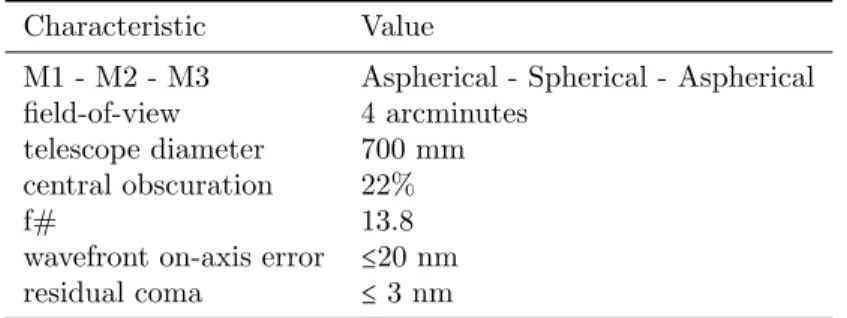
Currently the preferred option for its optical quality is a design based on the 3 mirrors Paul-Rumsey concept.4 The key characteristics of this design are given below in Tab. 4.1.
Table 5. Characteristics of the currently preferred option for the Salto telescope design.
Characteristic Value
M1 - M2 - M3 Aspherical - Spherical - Aspherical field-of-view 4 arcminutes
telescope diameter 700 mm central obscuration 22%
f# 13.8
wavefront on-axis error ≤20 nm
residual coma ≤ 3 nm
4.2 Laser system
Since sodium LGS are generated at much larger distance (about 90 km), their lower focal anisoplanatism makes them preferable to Rayleigh LGS (about 10 to 20 km). Of course, the larger the aperture the stronger the cone effect is, making sodium LGS indispensable for diffraction limited work on larger telescope apertures. But for modest aperture sizes, the focal anisoplanatism remains acceptable for apertures up to about 4 m (see for e.g. SAM on SOAR5).
Beside the cone effect, Rayleigh beacons are very attractive compared to sodium beacons :
• standard wavelengths from visible to UV pulsed lasers can be used. Therefore high power and good beam quality can be found commercially at small cost compared to sodium lasers.
• if the height of the beacon is kept at a relatively low altitude, the backscatter from air molecules is relatively strong. In addition, there are no complication with respect to variation of abundance or variation of the backscattering layers, as it is the case with the sodium.
• the scattering height can be chosen freely. It allows to trade off altitude with backscattered photons, possibly even once the system is built.5
• by slightly changing the time of flight, the LGS wavefront sensor focus can be adjusted. This is particularly useful to quickly close the loop in a stable way (see e.g. Argos6,7).
• the spot elongation is a free parameter that can be optimized on-sky. It allows to trade off return flux (longer gating time) and elongation in the outer subapertures - within the technological feasibility with respect to the gating unit i.e. the Pockels cell, a possible limitation for the smallest apertures.
Based on the forementioned arguments, we favor for Salto a laser Rayleigh system. As of now, we are planning on using a pulsed frequency doubled Nd:YAG laser at 532 nm. This is the result of returned photon flux versus technological trade-off where green laser appears to be overall more favorable compared to UV laser. The main advantage of UV laser is the absence of ocular hazards, making the beam safe to airplanes8 but also safer in the dome itself. Choosing green laser will therefore have a more stringent impact on our safety procedures. The laser power requirement is ≥ 10 W at a pulse repetition rate of about 10 kHz. The LGS will be focussed at about 10 km height, balancing focal anisoplanatism and wavefront measurement error (assuming a standard Hufnagel-Valley profile). From geometry itself a large gating height of up to 1.5 km could be considered, leading to a 2′′ spot on the most distant subapertures (side launch). In practice this will probably be limited to about 500 m due to limitation provided by the Pockels cells unit and its high-voltage driver. The optical design of the launch system will be refractive with a large aspherical lens at the exit. A fast tip-tilt mirror and a focus stage are also planned for uplink corrections.
4.3 AO module
The AO and imaging systems will sit on the Nasmyth focus of the demonstrator, providing a gravity gradient-free platform.
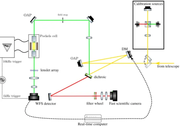
The optical layout is sketched in Figure3 and follows a classical scheme. After its focus, the beam from the telescope hits a first off-axis parabola re-imaging the pupil on the deformable mirror (DM) with a low incidence angle. After the DM, the beam is splitted by a dichroic. The laser light being reflected, while longer wavelengths are transmitted towards the imaging system. The laser beam is re-imaged to an intermediate focus where an appropriate field stop is placed to avoid “spilling” of light between adjacent subapertures. The light from about 10 km height is recollimated to enter the Pockels cell unit before the pupil being re-imaged on the lenslet array, finally projecting the Shack-Hartmann array onto the WFS detector. The “scientific” path will include ideally red-visible and near-infrared wavelengths to allow performance measurements at different wavelengths using a set of narrow-band filters. A calibration sources module is also planned to generate an artificial guide star and natural star (NGS), in order to perform calibration and closed-loop tests.
The key features of the system are currently :
• sub-electron readout noise EMCCD WFS detector, with 128x128 pixels and 1 kHz framerate.
• a large stroke DM with about 100 actuators to cope with the large amount of turbulence and possibly allowing for fast tip-tilt correction.
• No NGS tip-tilt correction but post-facto shift-and-add post processing implying a moderately fast scientific camera.
Figure 3. Concept sketch of the AO and imaging system for Salto sitting on the Nasmyth plateform.
• commercial Pockels cells. Based on previous experiences (e.g. Robo-AO9
or Argos7), a BBO‡ crystal between two crossed polarizers will be preferred for their high suppression and low ringing.
The Salto real-time computer (RTC) will be a standard multi-core workstation working under Linux. The real-time computation will perform the data calibration (dark and flat correction), spot centroiding using stan-dard center-of-gravity, slopes computation, and modal reconstruction of about 50 to 100 modes. The control law foreseen is a simple integrator with modal gain. The modal basis under consideration is a Karhunen-Lo`eve basis projected onto the mirror space. The same workstation will be used for the diagnostics acquisition and the user control of the AO system. A clear processes separation will therefore be mandatory and we will consider real-time patch on our operational system.
The real-time computation will be based on CPU. After a simple benchmarking evaluation of GPU (GTX 1080Ti) vs. CPU architectures, CPU-based computation is the preferred option due to the small scale of our computation and the data transfer overheads that the usage of GPU implies. For the software itself, we are considering open-access RTC software such as DARC§ or CACAO¶, with possible extension depending on our needs and specific hardware.
As part of a student project, we are also developing a device based on a micro-controller able to measure the total latency in our system : from camera readout trigger to the commands sent to the DM by its driver electronics. This will be a valuable tool to ensure that latencies are kept at a low level at all time. The same measurement will also be fed back to our simulations. We want to ensure that way of the correct implementation of our RTC and of having a reasonable temporal bandwidth.
‡β Borium Borate
§https://github.com/agb32/darc ¶https://github.com/cacao-org/cacao
5. CONCLUSIONS
Salto is a Belgian project aiming at developing our expertise in the development of LGS-AO system for medium size telescopes. Although it is a standard single conjugated laser guided adaptive optics system, the project encompasses all aspects of a small AO facility development : from site testing, to telescope design and dome infrastructure; from end-to-end simulations to the LGS and AO systems, including real-time computation and diagnostics analysis. By tackling all the aspects of an AO system, we hope to be able in the future to offer robust AO system for medium size telescope, and benchmark and test new concepts. The project is currently funded, with the objective of on-sky testing in less than three years.
ACKNOWLEDGMENTS
The authors acknowledge the support from the Walloon region of Belgium through the program Skywin (project Salto). GOX acknowledges support from the Beware Fellowships Academia program (convention #1610368). OA thanks the Belgian national funds for scientific research (FNRS).
REFERENCES
[1] Davies, R. and Kasper, M., “Adaptive Optics for Astronomy,” ARA&A 50, 305–351 (Sept. 2012). [2] Baranec, C., Riddle, R., and Law, N. M., “Automated Adaptive Optics,” ArXiv e-prints (2017). [3] Tokovinin, A., “From Differential Image Motion to Seeing,” PASP 114, 1156–1166 (Oct. 2002).
[4] Rakich, A. and Rumsey, N., “Method for deriving the complete solution set for three-mirror anastigmatic telescopes with two spherical mirrors,” Journal of the Optical Society of America A 19, 1398–1405 (July 2002).
[5] Tokovinin, A., Cantarutti, R., Tighe, R., Schurter, P., Martinez, M., Thomas, S., and van der Bliek, N., “SOAR Adaptive Module (SAM): Seeing Improvement with a UV Laser,” PASP 128, 125003 (Dec. 2016). [6] Orban de Xivry, G., Rabien, S., Busoni, L., Gaessler, W., Bonaglia, M., Borelli, J., Deysenroth, M., Esposito,
S., Gemperlein, H., Kulas, M., Lefebvre, M., Mazzoni, T., Peter, D., Puglisi, A., Raab, W., Rahmer, G., Sivitilli, A., Storm, J., and Ziegleder, J., “First on-sky results with ARGOS at LBT,” in [Adaptive Optics Systems V ], Society of Photo-Optical Instrumentation Engineers (SPIE) Conference Series 9909, 990936 (July 2016).
[7] Rabien, S., Angel, R., Barl, L., Beckmann, U., Busoni, L., Belli, S., Bonaglia, M., Borelli, J., Brynnel, J., Buschkamp, P., Cardwel, A., Contursi, A., Connot, C., Davies, R., Deysenroth, M., Durney, O., Elberich, M., Esposito, S., Frye, B., Gaessler, W., Gasho, V., Gemperlein, H., Genzel, R., Georgiev, I., Green, R., Hart, M., Kohlmann, C., Kulas, M., Lefebvre, M., Mazzoni, T., Noenickx, J., Ott, T., Orban de Xivry, G., Peter, D., Puglisi, A., Qin, Y., Quirrenbach, A., Raab, W., Rademacher, M., Rahmer, G., Rix, H. W., Rosensteiner, M., Salinari, P., Schwab, C., Sivitilli, A., Steinmetz, M., Storm, J., Veillet, C., Weigelt, G., and Ziegleder, J., “ARGOS at the LBT. Binocular laser guided ground layer adaptive optics,” ArXiv e-prints (June 2018). [8] Angel, J. R. P. and Lloyd-Hart, M., “Atmospheric tomography with Rayleigh laser beacons for correction
of wide fields and 30-m-class telescopes,” in [Adaptive Optical Systems Technology ], Wizinowich, P. L., ed., Society of Photo-Optical Instrumentation Engineers (SPIE) Conference Series 4007, 270–276 (July 2000). [9] Baranec, C., Riddle, R., Law, N. M., Ramaprakash, A. N., Tendulkar, S., Hogstrom, K., Bui, K., Burse,
M., Chordia, P., Das, H., Dekany, R., Kulkarni, S., and Punnadi, S., “High-efficiency Autonomous Laser Adaptive Optics,” ApJ 790, L8 (July 2014).