ATTRITION RESISTANCE OF CAO-CUO-CEM POWDER FOR CO2 CAPTURE IN CALCIUM LOOPING PROCESSES
PETER ASIEDU-BOATENG
DÉPARTEMENT DE GÉNIE CHIMIQUE ÉCOLE POLYTECHNIQUE DE MONTRÉAL
MÉMOIRE PRÉSENTÉ EN VUE DE L’OBTENTION DU DIPLÔME DE MAÎTRISE ÈS SCIENCES APPLIQUÉES
(GÉNIE CHIMIQUE) AVRIL 2015
c
ÉCOLE POLYTECHNIQUE DE MONTRÉAL
Ce mémoire intitulé:
ATTRITION RESISTANCE OF CAO-CUO-CEM POWDER FOR CO2 CAPTURE IN CALCIUM LOOPING PROCESSES
présenté par: ASIEDU-BOATENG Peter
en vue de l’obtention du diplôme de: Maîtrise ès sciences appliquées a été dûment accepté par le jury d’examen constitué de:
M. VIRGILIO Nick, Ph.D., président
M. PATIENCE Gregory S., Ph.D., membre et directeur de recherche M. LEGROS Robert, Ph.D., membre et codirecteur de recherche M. SAVADOGO Oumarou, D. d’état, membre
DEDICATION
To my wife Jennifer and kids Adriel and Edeline., Thanks for sharing your life with me. . .
ACKNOWLEDGEMENTS
I had the privilege to work with Prof. Gregory S. Patience who accepted me into his group and encouraged me to succeed even in very challenging times. I will never forget this. I would like to thank my co-supervisor Prof. Robert Legros for his advice and support during this work. Special thanks to Prof. Arturo Macchi of University of Ottawa for his exemplary project leadership and Natural Resources Canada for providing the sorbents. My gratitude also goes to members of my research group especially Dr. Christian Neagoe and Dr. D.C Boffito for their support. Technical staff Daniel Pilon contributed immensely towards the successful completion of this project. Thank you. I would finally like to acknowledge Carbon Management Canada for providing the funding and Natural Resources Canada for supplying the sorbent used in this studies.
RÉSUMÉ
La demande mondiale pour les combustibles fossiles continue d’augmenter, et les préoccupa-tions concernant l’émission de gaz á effet de serre et autres problèmes connexes n’ont jamais été aussi élevées.
La recherche de solutions au réchauffement climatique a reçu l’attention souhaitée et plusieurs technologies ont été développées. L’utilisation de solutions amines en tant qu’absorbant est maintenant disponible au niveau commercial, mais les coûts et les conséquences environ-nementales en limitent le déploiement. Les cycles à boucle de calcium (carbonate looping, CaL) sont également en développement, mais le recours à une unité de séparation de l’air très onéreuse pour la production d’oxygène pur est nécessaire.
Pour résoudre ces inconvénients, nous suggérons l’utilisation des technologies de solutions amines et des cycles impliquant des composés à base de carbonate de calcium (CaL) à capture de carbone ainsi que les techniques de séquestration.
Canmet Énergie a synthétisé un nouveau sorbant (CaO-CuO-ciment) qui permet d’intégrer les cycles à carbonate (CaL) á la combustion en boucle chimique (chemical looping combus-tion, CLC) pour l’utilisation dans des réacteurs á lit fluidisé. Ce couplage permet de cir-conscrire le besoin d’une unité de séparation de l’air. En vue de son utilisation, ce nouveau absorbant doit présenter une excellente tenue mécanique lorsqu’il est fluidisé. L’attrition des particules de l’absorbant survient en raison des collisions entre particules et avec les parois des réacteurs (en particulier dans les régions où des jets à haute vitesse sont présents). Peu d’essais d’attrition sont mentionnés dans la littérature pour des températures de 500◦C. Nous
proposons une étude permettant de simuler les conditions causant l’attrition des particules dans des réacteurs á lit fluidisé lors de cycles á calcium, incluant des essais menés à 800◦C.
La composition d’un absorbant est critique pour sa tenue mécanique dans de telles condi-tions. Nous avons mesuré le taux d’attrition pour quatre compositions d’absorbants dans un montage de taille industrielle et comparé celui-ci á celui d’échantillons de calcaire extrait à partir du minerai de cadomin ainsi que deux catalyseurs commerciaux : le pyrophosphate de vanadyle (VPO) et le craquage catalytique fluide(FCC).
Nous avons étudié l’effet de différents paramètres d’exploitation, telle que la vitesse du gaz dans l’orifice comprise entre 180 m s−1 to 240 m s−1, la masse volumique du gaz de fluidisation
(air, dioxyde de carbone et hélium), la calcination (absorbant calciné 800◦C durant 2 heures)
ainsi que la température (23◦C, 500◦C 800◦C). L’effet de la conception du système sur
de même que la composition de l’absorbant.
Dans chacun des essais, un échantillon de 20 g de poudre a été inséré dans un cylindre métallique puis de l’air passe à travers des orifices de dimensions interchangeables : des orifices de 0.39, 0.45 et 0.5 mm forés dans une plaque métallique permettant des vitesses de gaz entre 180 m s−1 á 240 m s−1 à des températures de 23◦C, 500◦C et 800◦C ont été utilisés.
La vitesse élevée du gaz influence la performance de l’absorbant ainsi que les contraintes mécaniques prédites sur les buses de barboteurs et la plaque de grille dans les réacteurs commerciaux à lit fluidisé. Les fines particules créées par l’attrition sont élutriées sur un tube d’une longueur de de 1.7 m et collectées dans un filtre, puis pesées. Le taux d’attrition du VPO et du FCC à une vitesse de gaz de 180 m s−1 sont de 5 et 7 mg h−1, respectivement,
alors que ce taux s’élève à 10 mg h−1 dans le cas du CaO
40−CuO50−cem10. Le CaO90cem10
présente une résistance à l’attrition 1.3 fois supérieure à celle du CaO40CuO50cem10. Ces
résultats démontrent qu’un ajout de 10 % de ciment augmente la résistance á l’attrition d’un facteur 1.5 par rapport au calcaire de Cadomin. Dans le cas des essais à des températures de 500◦C et 800◦C, le taux de génération des particules fines pour le CaO
40CuO50Cem10
n’a augmenté que de 6 %, probablement en raison de l’agglomération de celles-ci. Pour les mêmes températures, le taux de génération des particules fines a quasiment doublé pour le CaO90Cem10. Le taux de génération de particules fines varie de façon linéaire avec le débit
ABSTRACT
The global demand for fossil fuels continues to increase and concerns over emission of green-house gases and their associated problems has never been greater. Search for solutions to global warming has received the needed attention and several technologies are under devel-oped. Use of amine based liquid adsorbents are commercially available but cost and environ-mental consequences limit their frequent deployment. Calcium looping (CaL) is also under development but an expensive air separation unit is required. We need a technology that overcomes deficiencies in the use of amine based and CaL carbon capture and sequestration techniques.
Canmet Energy have synthesized novel sorbent, CaO−CuO−Cem with different composi-tions based on mass fraction, that integrates calcium looping (CaL) and chemical looping combustion (CLC) for fluidized bed applications with the view to eliminate the air separa-tion unit. The first criterion in accepting this sorbent is to ensure that it does not degrade mechanically during fluidized bed operation due to particle-particle and particle-containing vessel (at high velocity jetting regions) collisions .
Attrition test has been reported at temperature of 500◦C. We present an extensive attrition
study that simulates all possible conditions in fluidized bed during calcium looping including tests at 800◦C. A sorbent composition that optimizes attrition resistance is needed. We
have measured the attrition resistance of four compostions of the sorbent CaO-CuO-Cem in an industrial scale jet mill and compared them with those of crushed cadomin limestone and two other commercial catalysts: vanadyl pyrophosphate (VPP) and fluid catalytic cracking (FCC).
We studied the effect of orifice gas velocity (180 m s−1 to 240 m s−1), fluidizing gas density
(air, CO2 and He), calcination (calcined sorbent for 2 h at 800◦C) and temperature (23◦C,
500◦C and 800◦C). The effect of system design such as orifice diameter (0.39 mm, 0.45 mm
and 0.5 mm) as well as sorbent composition have also been investigated.
In each test, we charged 20 g of powder to a metal cylinder and passed air through an interchangeable single orifice of varying diameter: 0.39 mm, 0.41 mm and 0.5 mm drilled through a metal plate. The high velocity gas impinged on the sorbent, which mimicked the expected mechanical stresses at the nozzles of spargers and grid plate in commercial fluidized bed reactors. Attrited fines elutriated through a 1.7 m long tube and collected in a thimble filter. The attrition rates of VPO and FCC at at 23◦C and orifice gas velocity of 180 m s−1
were 5 mg h−1 and 7 mg h−1 respectively; it was 10 mg h−1 for the CaO
sorbent. CaO90−Cem10 was 1.3 times more resistant compared with CaO40−CuO50−Cem10.
These results show that 10 % cement increased attrition resistance of novel sorbent by 50 % as compared with base natural cadomin limestone. Due to agglomeration, rate of fines generation for CaO40−CuO50−Cem10 remained essentially constant when temperature was
increased from 500◦C to 800◦C. Over the same temperature range of 500◦C to 800◦C, rate
TABLE OF CONTENTS DEDICATION . . . iii ACKNOWLEDGEMENTS . . . iv RÉSUMÉ . . . v ABSTRACT . . . vii TABLE OF CONTENTS . . . ix
LIST OF TABLES . . . xii
LIST OF FIGURES . . . xiii
LIST OF SYMBOLS AND ABBREVIATIONS . . . xv
CHAPTER 1 INTRODUCTION . . . 1 1.1 Background . . . 1 1.2 Problem Statements . . . 7 1.3 Objective . . . 7 1.3.1 Main objective . . . 7 1.3.2 Specific objectives . . . 7
CHAPTER 2 LITERATURE REVIEW . . . 9
2.1 Sorbent attrition . . . 9 2.2 Mechanisms of attrition . . . 9 2.3 Assessment of attrition . . . 10 2.4 Grindability indices . . . 10 2.4.1 Attrition rate . . . 10 2.4.2 Attrition index . . . 12
2.4.3 Hardgrove index (HDI) . . . 12
2.4.4 Work index . . . 13
2.5 Attrition testing . . . 13
2.5.1 Jet mill attrition testing . . . 13
2.5.2 Jet cup attrition testing . . . 16
2.5.4 Cyclone attrition test . . . 18
2.5.5 Impact attrition testing . . . 19
2.6 Factors affecting attrition resistance . . . 20
2.7 Fluidized beds . . . 20
2.7.1 Particle characteristics . . . 23
2.7.2 Classification of powders . . . 23
2.7.3 Solids entrainment and elutriation . . . 24
2.7.4 Jet penetration . . . 26
2.7.5 Critical flow nozzles . . . 26
2.7.6 Grid design . . . 28
CHAPTER 3 ORGANIZATION OF THE THESIS . . . 30
3.1 Original scientific hypothesis . . . 30
3.2 Methodology . . . 30
3.3 Article . . . 30
CHAPTER 4 ARTICLE 1: ATTRITION RESISTANCE OF CaOxCuOycem1-x-y POW-DER FOR CO2 CAPTURE IN CALCIUM LOOPING PROCESSES . . . 32
4.1 Abstract . . . 32
4.2 Introduction . . . 32
4.3 Theory . . . 33
4.4 Experimental methodology . . . 37
4.4.1 Sorbents and catalysts . . . 37
4.4.2 Attrition mill . . . 38
4.4.3 Sorbent and catalyst properties . . . 38
4.5 Results . . . 41
4.5.1 Sorbent and catalyst attrition . . . 41
4.5.2 Effect of temperature . . . 46 4.6 Mechanism . . . 48 4.6.1 Orifice velocity . . . 51 4.6.2 Gas density . . . 53 4.6.3 Orifice diameter . . . 56 4.7 Conclusion . . . 56
CHAPTER 5 GENERAL DISCUSSION . . . 58
6.1 Advancement of knowledge . . . 60
6.2 Limits and constraints . . . 60
6.3 Recommendations . . . 60
LIST OF TABLES
Table 1.1 Choice of oxygen carrier for CH4 fuel in CLC [16] . . . 7
Table 4.1 Sorbents and catalyst particle size and bulk density . . . 37 Table 4.2 Under the attrition mill’s standard operating conditions the
equili-brated VPP had the highest attrition resistance. Cadomin had the highest attrition rate. The d50 of all the powders dropped after 24 h in
the attrition mill. . . 41 Table 4.3 The sorbent attrition rate decreases with increasing temperature. . . 48 Table 4.4 Best fit parameters for the attrition rate as a function of velocity based
on Eq. 4.8. The critical velocity increases with a decreasing value of the exponent. All three expressions fit the experimental data equally well. . . 53 Table 4.5 Eq. 4.8 normalizes all factors to standard conditions. Therefore, the
pa-rameter βoshould be invariant. It is constant for the CaO40CuO50cem10,
LIST OF FIGURES
Figure 1.1 Fossil fuel related carbon dioxide emissions trend [1]. . . 2
Figure 1.2 Schematic of calcium looping. . . 3
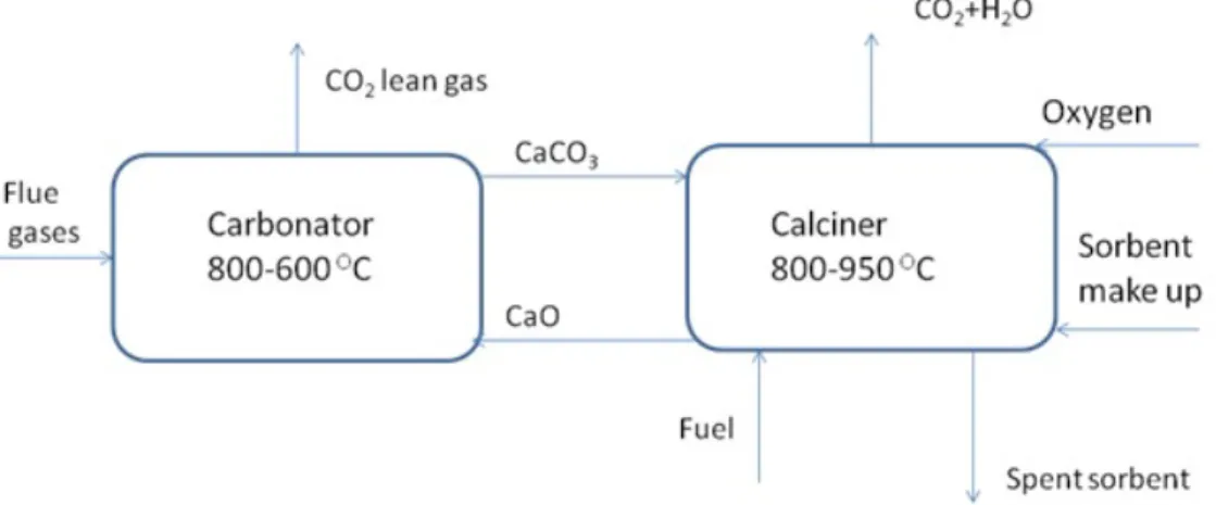
Figure 1.3 Schematic of integrated CaL-CLC system. . . 5
Figure 1.4 Schematic of chemical looping combustion. . . 5
Figure 2.1 : Modes of Attrition [29] . . . 11
Figure 2.2 Air jet attrition testing apparatus [39] . . . 15
Figure 2.3 Jet cup set up [58] . . . 15
Figure 2.4 Fluidization regimes [81] . . . 21
Figure 2.5 Pressure drop against fluidizing velocity for group B particles [81] . . 21
Figure 2.6 Geldart’s classification of powders [86] . . . 25
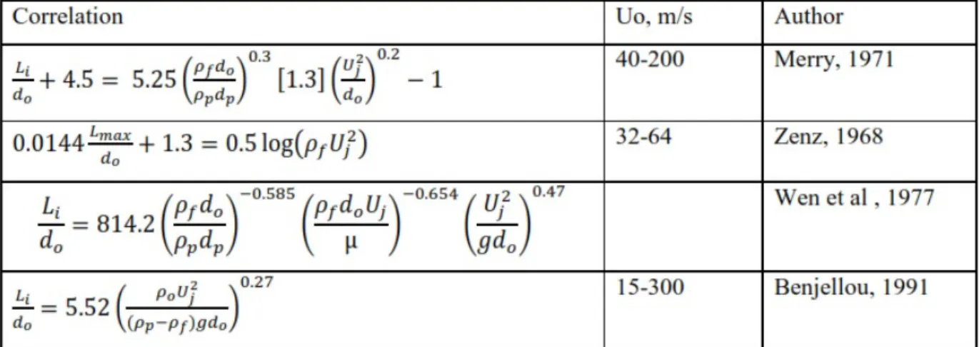
Figure 2.7 Correlations for jet penetration length . . . 25
Figure 2.8 Jet penetration length. . . 26
Figure 2.9 Flow nozzles . . . 27
Figure 2.10 Mach number variation with flow properties [102]. . . 27
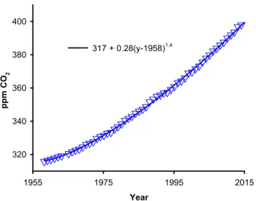
Figure 4.1 Historical atmospheric CO2concentration (ppm) reported by the Mauna Loa observatory [104]. . . 34
Figure 4.2 Jet attrition mill with a gas manifold for air, CO2, and He. The electric furnace is rated for 1000◦C. The mill is made of stainless steal that is flanged to a quartz tube 25.4 mm in diameter. . . . 39
Figure 4.3 SEM images show that after 24 h and at 800◦C, the sorbents are no-ticeably rounder. Suprisingly, the VPP particles fell apart at 500◦C. . . . 40
Figure 4.4 Effect of calcination on attrition rate. Calcining sorbents and VPP decreases mechanical stability. . . 42
Figure 4.5 The attrition rate is constant after 6 h for bothCaO10CuO10cem10 and CaO90cem10. . . 43
Figure 4.6 Symbols represent the PSD of uncalcined CaO40CuO50cem10 . The lines represent the difference in mass of solids for each particle size: black solid line is between 24 h and the virgin sample; the dashed red line between 96 h and 24 h. . . 43
Figure 4.7 The PSD of fines are similar after 6 h, 24 h and 96 h in the attrition mill. 45 Figure 4.8 Mass of CaO90cem10 in each size increment before and after the attri-tion test and the difference between the two curves. . . 45
Figure 4.9 SEM images of elutriated fines of CaO10CuO10cem10, CaO90cem10,
cadomin and VPP catalyst at 500◦C after 24 h. The fines from CaO
10CuO10cem10
and cadomin appear agglomerated. . . 47 Figure 4.10 The cadmonin elutriated fines were finer than all other powders we
tested. The cadomin before the attrition test and powder recovered from the jet cup had 7 % –20 µm. . . 47 Figure 4.11 The hollow symbols represent the PSD of VPP and FCC before the test
and the full symbols are the PSD after the test. The FCC elutriated fines are much finer than the VPP but no particles are greater than 20 µm. . . 48 Figure 4.12 Both the attrition rate and the fragmentation rate of CaO90cem10
in-creases with temperature. The +400 µm mother particles form as many –200 µm particles as +200 µm –400 µm. . . 49 Figure 4.13 The attrition rate of CaO40CuO50cem10 increases with temperature
but the +200 µm –400 µm particles agglomerate. An equal mass of +200 µm –400 µm particles disappear as +400 µm form. While the d50
increases from 310 µm to 420 µm, the dsv decreases from 260 µm to
240 µm because of the larger fraction of -200 µm. . . 49 Figure 4.14 Fresh VPP particle size distribution during the first 83 d of operation
in DuPont’s Circulating Fluidized Bed reactor [49]. . . 51 Figure 4.15 The attrition rate depends on gas velocity raised to a power. For a
value of β1 =4, best fit value for Uc = 0, for a value of β1 =3, Uc =
50 m s−1 and for a value of β
1 = 2, Uc = 100 m s−1. . . 52
Figure 4.16 The initial attrition rate of (during the first 6 h CaO10CuO10cem10, and
fresh FCC are double that of equilibrated VPP at all gas velocities. . 54 Figure 4.17 Effect of gas molecular weight on attrition rate. The effect of gas
density (molecular weight) and viscosity are confounded. The attrition rates correlates with the inverse square root of gas density. . . 54 Figure 4.18 Effect of orifice diameter on attrition rate. The attrition rate of catalyst
LIST OF SYMBOLS AND ABBREVIATIONS
Abbreviations
CaL Calcium looping
CCS Carbon capture and sequestration CLC Chemical looping combustion FCC Fluid catalytic cracking MEA Monoetanolamine
PSD Particle size distribution VPP Vanadyl pyrophosphate
English Letters
cem cement
K Attrition rate constant M Mass Ra Attrition rate U Velocity x Mass fraction Greek letters ρ density µ viscosity φ sphericity ξ voidage σ standard deviation
Subscripts
c cyclone g gas
i particle size class j jet
mf minimum fluidization o orifice
p particle
CHAPTER 1 INTRODUCTION
1.1 Background
Global warming, which is due mainly to increasing concentration of atmospheric carbon dioxide has recently gained much attention. The atmospheric carbon dioxide concentration increased by 0.7 % between June 2012 and June 2013 [1]. Almost two-thirds of these increase is related to coal, 22 % to oil and 15 % to natural gas. Fossil fuel will continue to be used well into the current century and the problems associated with global warming will prevail unless mitigation plans are put in place (Fig. 1.1).
Carbon capture and sequestration (CCS) techniques are key option to mitigating CO2
emis-sions [2]. Carbon sequestration refer to process of capturing CO2 from it emission sources
whereas carbon storage is method of permanently injecting it deep underground, sea, gas fields, rocks, coal seams and saline aquifers to prevent it from having effect on the environ-ment. Both sequestration and storage can interchangeably refer to injection of CO2 more
than 1 km deep into geological formations. Carbon sequestration reduces green house effect but brings additional operational cost. During storage CO2 is pumped underground, rise
and reach an impermeable cap rock (via buoyancy flow). Storing CO2 in the sea can form
carbonic acid and destroy aquatic life. Underground storage may cause leaks and re-emission into the atmosphere (can be fatal if concentrations exceed 10 %). Well blow-outs can also be catastrophic [2, 3].
Carbon sequestration and storage by mineral carbonation involving the exothermic reaction of CO2 (in mineral form) with alkaline compounds leads to geological stability and may prevent
future leakages. The high energy requirement (350 MW for 100 % storage of emissions from 1.3 GW of coal fired power plant) is its major setback. Mineral carbonation have the capacity to store 20 Mt per annum of CO2 in the form of MgCO3 . Metal organic frameworks (MOFs)
with adjustable chemical functionality and high porosity also provide effective means of carbon storage but they still remain remain at laboratory level with additional disadvantage of handling high volumes of chemicals [2].
According to Yang et al [4], reduction in atmospheric CO2 concentration can be achieved
either by cutting down on the use of fossil fuels or by incorporating carbon capture and sequestration technologies. It will be difficult to reduce the use of fossil fuels significantly although efforts are being made to increase the percentage of other sources of energy such as renewable and nuclear. This is due to the fact that fossil fuels contribute 80 % to global
Figure 1.1 Fossil fuel related carbon dioxide emissions trend [1].
energy demand and replacing fossil fuels with nuclear energy will not be feasible in the short to medium terms.
Presently, the only commercially available CCS technology is the low temperature chemisorp-tion of CO2 using amine based solvents. This involves bringing flue gas containing CO2 into
contact with aqueous monothanolamine (MEA) flowing counter-currently. The CO2 as a
weak base reacts with MEA which is a weak acid to form a water soluble salt. The reaction is reversed in a stripper after treating it thermally to recover the CO2. Despite the inherent
advantages of amine scrubbing such as its applicability even at low concentration and dilute CO2 system, several disadvantages limit the use of MEA for CO2 capture. For instance the
huge energy requirement of 3.8 GJ/t CO2 for the CO2 recovery process since the solvent is
heated to 100◦C-120◦C to provide the desorption heat. The solvent must also be heated
to the stripper temperature (100◦C-120◦C) during the capture process. Additionally,
pos-sible corrosion of process equipment, solvent degradation and the negative impact on the environment renders amine scrubbing unattractive [5, 6].
Membrane separators which capture CO2 by size exclusion or through affinity for CO2 are
less energy intensive with equivalent amount of CO2 captured. Frequent material corrosion
issues make membranes less attractive. Oxy-combustion CO2 capture produces 90 % pure
Figure 1.2 Schematic of calcium looping.
problems. Membrane and CO2/O2 techniques are promising but they not yet mature for
industrial applications [3].
The cost of capture step in CCS is the highest (USD15-75/t of CO2 captured) compared to
transportation (USD 1-8/t CO2 captured) and storage (USD 0.5-8/t CO2 captured) [1]. The
high cost of CCS and the demerits associated with MEA have led to the search for more cost and environmentally effective alternative technologies for CO2 capture. Towards this end,
the use of solid sorbents especially calcium oxide in carbonation-calcination reactions, have gained prominence as potential CCS technology [7, 8] with possibility of capturing CO2 with
better process economics and energy efficiency [8, 9, 10]. The average cost of MEA capture is (USD 50/t CO2 captured) which is equivalent to 0.03 $/kWh [5, 6] but Abanades et al
[8] showed that with Ca-based sorbents cost of CO2 capture can be as low as (USD 15/t
CO2 captured) translating into 0.0075 $/kWh mainly because of the power generated by the
capture system.
Calcium oxide (abundant and inexpensive limestone which is cheaply abundant) reacts with CO2 -rich flue gas typically at a temperature of 600
◦C in carbonation reaction (I) as
illus-trated in Fig.1.2
CaOs+ CO2 −−→CaCO3 (I)
The reverse calcination reaction, which usually occurs at temperatures above 800◦C
(depend-ing on the equilibrium) separates CO2 for subsequent compression and geological storage.
of calcium looping (CaL) process is usually high due to the expensive air separation unit [12, 13, 14]. Moreover, regenerating the sorbent at high temperature during oxy-fuel com-bustion sinters and leads to reduction in sorbent activity to capture CO2. Burning solid fuels
(which contain SO2) will reduce the performance of the solid sorbent. Oxy-fuel combustion
usually results in corrosive CO2 stream. This situation makes CO2 unsuitable for transport
by pipelines. However, simulations conducted on experimental data in [9, 10] show that high temperature CCS with solid sorbents can lower the cost compared with low temperature MEA. The cost effectiveness and energy efficiency of calcium looping (CaL) can further be enhanced when integrated with chemical looping combustion (CLC) utilising oxygen carriers such as copper with aim of averting problems associated with individual technologies and producing electricity (Fig.1.3).
Chemical looping combustion operates with two interconnected reactors: fuel reactor and air reactor (Fig. 1.4). A metal oxide which serves as a source of oxygen circulates between these reactors and combustion process is separated into oxidation and reduction reactions [13]. Oxidation of the fuel takes place in the fuel reactor and produces CO2 and water vapour
(reaction II). The reduced form of the metal oxide is re-oxidized in the air reactor (reaction III) and returned to the fuel reactor to begin another cycle.
(2 n + m)MeyOx+ CnH2m −−→(2 n + m)MeyO(x-1)+ mH2O + nCO2 (II)
MeyO(y-1)+
1
2O2 −−→MeyOy (III)
Pure CO2 is obtained after condensing the water vapour. This eliminates the need for
extra energy intensive air separation system and thus improves the economics of the process [3, 13, 14]. The heat of reaction remains unchanged compared with combustion in which both air and fuel contact with each other directly.
The efficiency of CLC is dependent on the choice of oxygen carrier. Oxides of transition metals such as Cu, Ni, Fe, Co and Mn are effective. Selection criteria of oxygen include flu-idizability, stability and reversibility during reduction-oxidation reactions, attrition resistance and tendency agglomeration resistances (for fluidized bed applications) etc. Environmental and health issues as well as material availability and cost are also considered. The oxygen carrier determines the heat distribution between the interconnecting reactors. Exothermic reduction reactions by oxygen carriers are the basic condition that must be met for it to be applied in an integrated CaL-CLC. In the calciner (fuel reactor), the energy released during the exothermic reduction of the oxygen carrier is used to decompose the CaCO3. Cho et
Figure 1.3 Schematic of integrated CaL-CLC system.
al [14] compared the properties of many transition metals oxides and concluded that nickel based oxygen carrier are the most promising. Contributions from [16, 17] indicate that cop-per based oxygen carriers are exothermic during reduction reactions thus avoiding the need for energy supply.
Manganese oxides can be used since they undergo exothermic reduction reactions [16]. How-ever only Mn3O4/MnO cycles can be used at 600
◦C to 800◦C and 800◦C to 950◦C (typical
CaL-CLC conditions) and reaction with CH4 is endothermic. The critical parameter for
selection of oxygen carrier is the specific heat of reduction (Table 1.1) to generate energy; and CuO is the best since it has the highest specific heat of reduction with CH4. Copper,
however, suffers agglomeration and sinters above 950◦C blocking lattice sites as well as
sub-stantial reduction in reactivity as the number of cycles increases. The energy released from reduction of CuO with gaseous fuels such as CH4 is used to decompose CaCO3. Both the
carbonation (reaction I) and oxidation (reaction IV) of copper are exothermic and the heat released can be used to generate electricity [18].
2 Cus+ O(2g) −−→2 CuOs (IV)
4 CuOs+ CH4(g) −−→4 Cus+ 2 H2O + CO2 (V)
Fluidized beds are the reactors of choice for practical implementation of CaL since they provide effective means of contacting gas and solids and offer good means of heat and mass transfer [19]. A number of studies have been conducted with focus on bubbling beds [19, 20] and circulating fluidized beds [21, 22]. High fluid velocities in these reactors (depending on the operating regime) usually cause solid particles to collide at high frequency with each other and with walls of the containing vessel. Momentum transfer during collision leads to particle attrition (mechanical degradation).
Sorbent attrition produces fine particles that can be elutriated and must be replenished. Attrition is an undesirable phenomena especially with sorbents containing expensive and toxic copper oxide as it results environmental and health concerns and icreases operational cost. In an effort to finding a cost effective and energy efficient CCS technology, Canmet Energy is developing novel sorbents that integrates CaL and CLC [12, 23]. Testing the attrition resistance of the novel sorbent is the first critical undertaking in commercialising this technology together with fluidized bed carbonation/calcination cycles test of reactivity.
Table 1.1 Choice of oxygen carrier for CH4 fuel in CLC [16]
Oxygen carrier Heat of reaction, kJ/mol Specific heat, kJ/kg.
CuO-Cu -211.6 0.66 Cu2O−Cu -139.9 0.24 NiO−Ni -83.5 0.58 Mn2O3−MnO4 -446.3 0.24 Mn2O4−MnO -92.2 0.41 Co3O4−CoO -30.3 0.03 1.2 Problem Statements
1. High fluid velocities in fluidized beds cause high frequency sorbent particle-particle and sorbent particle-reactor wall collisions. This results in momentum transfer between particles leading to mechanical degradation (attrition) of sorbent particles, production of fine particles and subsequent elutriation of fines.
2. High temperature requirement in calcium looping-chemical looping combustion may agglomerate and sinter sorbent and reduce sorbent reactivity performance.
3. Reduction in the mechanical and reactivity performance of sorbents require the addition of fresh sorbent. This increases the operational cost of calcium looping processes.
1.3 Objective
1.3.1 Main objective
As part of development of CCS technology by Carbon Management Canada, the main ob-jective of this thesis is to test the attrition resistance of novel sorbent for post-combustion CO2 capture and ascertain its suitability for fluidized bed operations.
1.3.2 Specific objectives
The main objective of this thesis has been divided into three sub-objectives:
1. Establish an attrition test protocol that is valid for commercial CaL-CLC operations. 2. Determine the effect of operating conditions such as temperature, orifice gas velocity,
gas density and duration of test as well as effect of orifice diameter on the attrition resistance of the sorbent.
3. Identify sorbent composition that maximizes attrition resistance.
The novelty of this work relates to operating the attrition mill at 800◦C, which has never
been done before.
This study determines the attrition resistance of Ca-based aluminate cement bound sorbent with four compositions in a jet mill and compares them with crushed cadomin limestone and two other commercial catalysts: DuPont’s vanadium pyrophosphate (VPP) and fluid catalytic cracking (FCC).
The sorbent prepared by Canmet Energy, contains varying amounts of calcium aluminate cement as binder aimed at optimising its attrition resistance. We conduct test at tempera-tures up to 800◦C using an industrial jet attrition mill that was employed by DuPont during
the development of VPP catalyst. The testing condition simulate industrial fluidized bed reactors to be employed during the commercialization of this technology. The results of this study can, therefore, guarantee the expected attrition issues or otherwise in real calcium looping process as it will incorporate effects of both material properties as well as process conditions and system design.
CHAPTER 2 LITERATURE REVIEW
2.1 Sorbent attrition
In a fluidized bed reactor, the bed is most of the time in a rigorous motion and this usu-ally results in high frequency particle-particle and particle-wall collisions. Collision leads to mechanical degradation of bed material. Particles surfaces are abraded or the entire particle could fragment.
The possible elutriation of attrition generated fines can have serious implications on safely of equipment, personnel, environment and operational cost. Fine particles of materials with toxic compounds leads to health and environmental issues. Wear of containment vessels and system contamination may also occur as result of attrition. If fine material builds up in systems, it may lead to an explosion. Elutriation of material from reactors means that it must be regularly replenished which creates additional material cost and may render the entire process economically unattractive [24]. Attrition changes the particle size distribution in a reactor during operation and affect the hydrodynamics, reaction rate, heat and mass transfer [25, 26]. Most attrition tests focused only on material properties to determine the attrition resistance [27]. A complete attrition test must account for process conditions and system design as well. Vaux and Kaeairins [28] investigated the effect of thermal stress, chemical stress and mechanical stress on sorbents and found that each of these process factors have significant effect on materials attrition resistance. Material properties such as particle size distribution, surface structure, and shape can seriously influence its attrition resistance. Attrition test must consider conditions such as gas and solids velocity, solids residence time, system temperature and pressure. Orifice diameter, grid type, wall hardness are the main design variables [29]. Studying attrition enables one to understand the mechanism and find a suitable model to predict the extent of anticipated attrition of sorbents [30] and efficient design of fluidised bed reactors [31].
2.2 Mechanisms of attrition
During abrasion (Fig. 2.1) asperities on surfaces of particles are chipped off leading to more rounded and large number of finer particles (narrow size distribution). The particle size distribution becomes bimodal as compared with the original unimodal particle distribution. Particles abrasion occurs easily as it requires just a minimum threshold energy. The particle size distributions of the parent particles do not change significantly. In fragmentation, the
particle breaks into a large number daughter particles usually of the same order of magni-tude as the parent particle. The results of particle fragmentation is a wider particle size distribution compared to the parent particles [29, 30].
2.3 Assessment of attrition
Several factors have to be considered in order to measure the attrition resistance of a material. Individual particles or group of particles can be used to assess attrition in a wide range of methods based on a variety of empirical indices [32]. Attrition resistance of a material can be determined in terms of materials loss or changes in particle size distribution when it subjected to specific stress. Gwyn [33] estimated the generation of fines with time and stated that attrition rate increase with time. Epstein [34] developed a method that measured the degree of fragmentation based on two functions: probability of solid to fragment with a time interval and fraction of fragmented products with a particular size range.
2.4 Grindability indices 2.4.1 Attrition rate
Attrition rate (Ra) is defined in terms of the fractional reduction in mass (M) of material with time due to elutriation of generated fines (Eq. 2.1 and 2.2). This is the usual method of assessing the attrition resistance of a material in fluidized bed operations. Reduction in the mass of bed material or mass of entrained and subsequently elutriated fines generated is measured [35]. Raj = − 1 m dme dt (2.1) Raj= dme dt (2.2)
However, depending on the available resources and data required, different authors have defined attrition rate (Equation 2.3) based on changes in the particle size distribution [36].
Raj = −
1 do
ddN
dt (2.3)
where do and (dN) are particle median diameters at the start of a test and after N cycles
Figure 2.1 : Modes of Attrition [29] .
Based on production of fines greater than 325 mesh ( 44 µm), Forsythe and Hertwig [37] gave the attrition rate as a percentage per hour (Eq. 2.4).
Ra =
(% of − 325 mesh at start − (% of − 325 mesh after 1h)
(% of − 325 mesh at start) X100 %/h (2.4) Equation 2.4 is applies to just a specific size class of particles and 1 h test duration. Moreover, it does not consider fines that are kept in the attrition zone as these have an effect on the friability of the material.
Gwyn [33] improved on the work of Forsythe and Hertwig, and estimated the attrition rate with mass-time relation (Eq. 2.5). Gwyn’s equation later gave birth to the ASTM D5757 method.
Raj= ktm (2.5)
where m is lies between 0.43 - 0.9, t is time and k is an attrition constant which decreases with particle size and is valid for only size distribution [38]. Gwyn’s relationship indicates that attrition increases with time. This is only true when steady state attrition rate is not attained. Attrition rate is dependent to a large extent on the conditions of elutriation in the test apparatus.
2.4.2 Attrition index
The ASTM D5757-11 standard [39] uses percent fines at five hours of operation to evaluate the attrition index [Eq. 2.6] with particles in the 10 µm to 180 µm range of fluid catalytic cracking catalyst. Eq. 2.6 calculates the attrition rate as the fraction of fines collected to total mass charged to the mill. The test duration is 5 h. The first 5 h of operation may only give an indication of the initial attrition. The test must be extended to include the attrition rate under steady state conditions. The particle size range contains fines which can easily be elutriated and may increase the recorded the attrition rate. Several suggestions were given to improve on the ASTM method in [40].
Raj= −
(M1− Mo) + (M5− Me)
Ms
X100% (2.6)
Mo = mass of empty fines collection system at start of test.
M1= mass of fines collection system after 1 h. Mass of collection system and fines collected
during the first 1 h.
Me = mass of second empty fines collection system. This installed after 1 h to collect the
fines.
M5 = mass of second fines collection system after 5 h. Mass of collection system and fines
collected during the last 4 h. Ms = mass of sample.
2.4.3 Hardgrove index (HDI)
This is based on newly produced surfaces during size reduction process of material sample of nearly equally sized particles. The new surface produced is compared as a percentage with that of a standard coal. The ASTM standard D409/D409M-12 [41] calculates the value of the index according to equation (2.7)
HGI = 6.7M + 10.63 (2.7)
where M = mass of 75 µm ( No 200) mesh material. The fines are produced during 60 revolutions of material with particles between 590 µm to 1190 µm in ball-ring pulveriser. Only relative hardness values are obtained since the mill is calibrated with coal which is assigned a hardness value of 100.
2.4.4 Work index
Work index is the kWh needed to mill 900 kg of material from an large particle size until 80 % of the particles are less than 100 µm. This can be calculated with (Eq. 2.8) [42]. Large quantity of test material needed limits its applicability to large scale operations.
Wi= 44.5 P0.23 t × G0.83e (P800.510 − 10 F0.5 80 ) (2.8)
Pt = size of test sample, Ge = grindability (g/rev), P80= product size(1 µm), F80 = feed size
(1 µm).
2.5 Attrition testing
Attrition tests may be carried out using any of the several experimental processes including ASTM-D5757 by air jet [39], jet cup [43], fluidised beds [44] and cyclonic [45, 46]. These test methods suggest that there is no universal method for assessing the attritability of a powder. Ranking the relative attrition resistance of different materials after subjecting each to different stresses can lead to conflicting results. According to [47]
“If we took a batch of rubbers and a batch of diamonds, and rubbed them on abrasive paper, we would conclude that the diamonds were more attrition resis-tant. If we instead struck the particles with a hammer we would conclude that the rubber were more attrition resistant”.
The method to be used in testing attrition resistance should simulate the real situation and stress to be experience in commercial processes.
2.5.1 Jet mill attrition testing
The jetting region of a fluidized bed is a major source of attrition. The jet attrition test method mimics catalyst attrition in the jetting region of distributor in a fluidised bed reac-tor. This involves introducing gas through an orifice at high velocity to impinge on sorbent (Fig.2.2). The powder particles collide at high frequency leading to mechanical degradation. The fines generated are entrained in the gas and entrainment rate remains constant and independent of particle diameter after reaching saturation stage.
Contractor et al [48] measured the attrition resistance of catalyst in jet mill during the development of DuPont’s butane oxidation process. Patience and Bockrath [49] employed
a jet mill to measure the attrition resistance of powder. An attrition rate of 4 mg h−1 was
achieved when an orifice velocity of 210 m s−1 passed through a 0.4 mm orifice. The high
attrition resistance was attributed to heat treatment in the spray dryer that gave higher catalyst bulk density. The attrition resistance of limestone from 0.5 h to 144 h has been measured in jet apparatus [50]. A model with an exponential function was developed to characterise the attrition process. The fines generation rate was inversely proportional to the particle volume for the initial and stable stages. The effect of attrition resistance of catalyst in an acrolein process was tested with an air jet apparatus with a 0.4 mm orifice in [51]. The concentration of the salt was higher in the attrited fines than the catalyst in the mill. The extent and pattern of limestone attrition by surface wear in the dense phase fluidised bed has been studied [52]. Attrition of particles caused by impact was dependent on impact velocity. Limestone particle attritions under oxyfiring condition have been investigated with similar procedure as in[53]. The attrition behaviour of CaO nanoparticles has been investigated with an air jet apparatus under high temperature and ordinary conditions. Results showed that Ca12Al44O13 formed under calcination conditions. Attrition resistance increased with Ca/Al
ratio and attrition mainly occurred in the region of CaO particles [55].
Larger initial particles experienced higher attrition rates because they possessed greater en-tropy (measure of disorderliness in particle size) and higher chance of being involved in colli-sions [55]. Disordered particle size resulted in higher frequency of attrition-causing collicolli-sions. Mechanism of limestone attrition in jet mill was investigated in [30] for different particle size ranges. Abrasion was the main mechanism for particles of size 710 µm to 850 µm in diame-ter but it changed to total fragmentation as the size decreased below 180 µm. Werther and Xi [56] studied the mechanism of jet induced attrition with a Gywn type of apparatus and proposed a model (Eq. 2.9) for the attrition rate. They related the surface energy created with the energy spent. Where Kj is material specific attrition constant, ρg is gas density, do is orifice diameter, Uo is orifice gas velocity.
Raj= n0kjρgdpd2OU
3
O (2.9)
Catalyst attrition is much greater at high orifice velocities and larger orifice diameter due to increased mass flowrate which induce higher frequency of collisions. ASTM D5757[39] is the most common testing method with a high gas velocity through the orifice and much reduced velocity in the bed. Thus it takes long a time to attrit the catalyst. Ghadiri et al[57] established a more general relation for attrition rates of FCC catalyst using single particle impact in the jetting region of fluidised bed and predicted 3.31 for the exponent.
Figure 2.2 Air jet attrition testing apparatus [39] .
Figure 2.3 Jet cup set up [58] .
2.5.2 Jet cup attrition testing
The Most common jet cup used is the Grace-Davidson model, which has a tangential gas inlet attached to a disengagement chamber (Fig. 2.3). A gas velocity of 150 m s−1 generates
fines in the cup which are carried into the disengagement chamber. The process continues but fines escape through the outlet when they become small. This requires less powder sample as compared to cyclone attrition testing. An index of attrition representing an increase in weight fraction of fines less than 20 µm is calculated after an hour of test.
Ryden et al [58] measured the attrition resistance of two oxygen carriers meant for chemical looping combustion applications: NiO and Fe2O3 as active phase carriers with Al2O3 or
MgAl2O4 as support. Freshly prepared oxygen carriers showed higher attrition resistance
compared with those that have gone through cycles of chemical looping combustion with natural gas. Attrition resistance of the particles from the jet cup were also compared with their individual crushing strength. Cocco et al [43] increased the Davidson jet cup diameter to 7.6 cm and used it to compare the attrition resistance of equilibrium FCC catalyst and proprietary catalyst. Results from attrition studies with the conical jet cup were similar to results from a fluidised bed test. Attrition rates from the cylindrical jet cup were 10 % to 30 % lower compared with the conical jet cup. Zhao et al [59] evaluated the attrition resistance of slurry bubble column reactor (SBCR) catalysts with an ASTM based system. Fragmentation was the major cause of catalyst attrition. Attrition rates of SBCR catalyst in the jet cup and ASTM fluidised bed were similar [30]. Conditions in the jet-cup only simulate the degree a material’s friability in cyclone and may not necessarily give the attrition rate at the distributor region in a fluidized bed reactor.
2.5.3 Fluidised bed attrition test
During fluidised bed operations, catalysts experience collisions with each other and with the walls of the reactor. This causes attrition due to abrasion and fragmentation which leads to elutriation of fines. The importance of this phenomenon has led to a number of investigations involving attrition behaviour of lime containing sorbents for CO2 capture. Chen et al [63]
investigated the attrition behaviour of synthetic sorbent supported with aluminate cement in a fluidized bed reactor. Optimal carbonation/calcination conditions were employed and the effect of parameters such as time, particle diameter and number of cycles and attrition rate based on median particle size (Eq. 2.10 ) were studied.
Ra = −
1 D50,0
dD50,N
where N is the number of cycles, D50,0 and D50,N are the median particle diameters at initial
and after N cycles respectively. The attrition rate was higher at high temperatures and during initial cycles. Equation 2.10 only measures attrition rate with respect to single particle and may not give a true reflection of attrition resistance of the material.
The attrition resistance of five limestones were investigated in a lab- scale circulating fluidized bed (CFB) reactor and pilot-scale CFB [36]. The attrition rate was calculated with (Eq. 2.11)
Ra = −
1
M+75,t
dM+75,0
dt (2.11)
where M+75,t and M+75,0 represent mass of particles in the bed at time t and time zero;
with size greater than 75 µm as beyond which attrition did not occur. Agglomeration due to wall effect occurred in the lab-scale CFBC reactor but calcination in the pilot-scale CFBC resulted in the sample losing 43 % of its weight. High velocities in a circulating fluidised bed can attrit particles greater than 75 µm. Similarly Gonzalez et al [64] investigated the attrition of two limestones at typical calcination/carbonation conditions in a CFB reactor. Attrition rate was higher during the first few cycles but it levelled off afterwards. Data was fitted with existing semi-empirical correlations to obtain the attrition rate constants.
The effect of time, gas velocity, temperature on limestone particle attrition was studied in a CFB reactor from 25◦C to 850◦C [65]. Attrition rate decreased at higher temperature
probably due to changes in gas properties. An Arrhenius type of correlation was developed to describe the mean particle size. Broda et al [66] synthesized a calcium based sorbent stabilized by Al2O3 from the sol-gel technique and tested the attrition resistance of the
sorbent in fluidised bed reactor. Results showed that attrition resistance of the material increased with increasing content of Al2O3. Charitos et al [20] performed an analysis of the
attrition behaviour of calcium based sorbent using a 10 kWth dual fluidised bed reactor. The PSD of the raw CaCO3 and CaO were determined at specific times. The rate of attrition was
2 % h−1. Attrition resistance (in terms of extent of attrition) of limestone and a synthetic
sorbent supported with calcium aluminate cement have been measured at low and high temperature using a fluidised bed reactor. The synthetic sorbent had lower attrition rate compared with the natural limestone [67]. Pacciani [68] investigated the effect of CaO content on the attrition resistance of synthetic sorbent in a 30 mm diameter quartz reactor. The mass of elutriated fines was calculated from the difference in mass after the 20th cycle of carbonation and calcination. When the content of CaO was increased from 50 % to 75 %, the attrition rate increased 10 times. The criteria set by Vaux and Keairins have been applied in [69] to assess the attrition behavior of Ca-based sorbent by imparting four types of stress:
mechanical, kinetic, chemical and thermal, which are likely to be experience in fluidized bed operations. Cement seemed to have improved the attrition resistance in all stress cases. Fennell et al [70] have tested the attrition resistance of Purbeck, Cadomin, Penrith, Glen Morrison and Havelock limestones in 30 cm reactor. Cadomin attrited more than any of the limestone with 9 % attrition rate in the first carbonation/calcination cycles but levelled off in subsequent cycles. A pilot scale dual fluidized bed system was used to test the attrition resistance of havelock limestone [71]. The reactor was made of calciner/regenerator in the circulating mode at 900◦C and and carbonator was fed with 15 % to 16 % CO
2. With feed in
the range of 400 µm to 600 µm, fines of about 100 µm microns were captured in the cyclone and attrition was significant even up to the 25th calcination/carbonation cycle.
Bubble velocity cause intra particle collisions in fluidized beds. Various research groups have proposed several correlations for bubble induced attrition. Pis et al [72] found that the bubble attrition rate is independent of bed height (Eq. 2.12) but according to Xi [73], the rate is proportional to bed height (Eq. 2.13)
Ra,bub = kbub(Ug − Ug,mf) (2.12)
Ra,bub = kbub(Ug − Ug,mf)H (2.13)
where the abrasion rate constant is (kbub) and (Ug−Ug,mf) is the excess gas velocity. Result from (Eq. 2.13) is more reliable as mass of elutriated fines depends on whether or not the height exceeds the transport disengagement height.
Fluid velocities in most laboratory fluidized bed attrition test are of the order of 1 m s−1which
may not able to induce any significant attrition. Moreover, perforated plate distributors which are preferred in industry cannot be used as they tend to induce jet attrition.
According to Thon et al[74], fluidized bed is the main source of catalyst attrition after simulating commercial conditions on the various vessels of in circulating fluidized bed.
2.5.4 Cyclone attrition test
The cyclone is an important part of circulating fluidised bed system. Operations such as removal of fine particles from gas stream in cyclones usually lead to catalyst attrition. Thon and Werther [75] tested the attrition resistance of both used and fresh VPP and compared with FCC. The VPP was subjected to mechanical stress in gas cyclone. The
rate of attrition was higher for the fresh catalyst than the used VPP catalyst. The attrition propensity for VPO was also lower than that of the FCC. The mechanism of different catalysts attrition in cyclones was investigated by Reppenhagen and Werther [76]. They developed a model to relate the surface created by the attrition process to the spent kinetic energy. The attrition rate was found to be proportional to the surface mean diameter of the material. Catalyst attrit as they pass through cyclones in circulating fluidised bed. The solid loading, gas velocity and particle diameter are main factors influencing cyclone attrition. Abrasion dominated attrition can be calculated according to (Eq. 2.14) [29]
Ra,c= KcUcnU
2
c,in (2.14)
where Kcis cyclone attrition rate constant, Uc,in is the solid-to-gas loading, n shows a power
law dependence of attrition rate on the gas velocity, Uc.
Only few studies on cyclone attrition have been reported since a circulating fluidized bed must be installed. Other factors such as solids circulation and initial elutriable fines might contribute to the attrition rate in the cyclone.
2.5.5 Impact attrition testing
A test sample is entrained in gas flowing at a specific velocity to impact a target. The impact velocity is a combination of the gas velocity and the terminal velocity of the particle. Particles are collected and analysed after impact.
Scala et al [77] tested the impact damage propensity of lime stone. Attrition rate varied with impact velocity. Particle impact attrition was also carried out at 25◦C to 580◦C and
velocities between 9 m s−1 to 64 m s−1. A model to predict particle evolution of particle
size distribution taking mass transfer between numbers of size classes was developed. The temperature effect on attrition rate followed the Arrhenius dependency. Lower attrition rates occurred at higher temperatures [78]. Similarly Chen et al [79] performed impact attrition of limestone at 25◦C to 580◦C and 20 m s−1 to 100 m s−1 impact velocity. Attrition
rate decreased with increasing temperature due to reduced impact velocity and the impact activation energy was 5.2 kJ mol−1. This test method however does not simulate attrition
2.6 Factors affecting attrition resistance
Attrition resistance of a material depends on three factors; process (temperature, pressure, velocity, time) and material factors (particle size, shape, porosity) and system design (orifice and distributor design). The conditions that prevail during attrition test dictates the attri-tion propensity of the material. Increasing temperature of gas reduces momentum transferred to materials through the density of the gas, thus decreasing the attrition rate of the material. However, some studies have shown that attrition rate of certain materials such limestone increase with increasing temperature due to changes in material properties. Similarly, in-creasing the pressure of the gas increases the attrition rate since the volume of gas decreases at higher pressure. The attrition rate increases with test time in a non-linear fashion. Cairati et al [60] investigated the effect of time on attrition rate and concluded that the 1h duration may be insufficient for catalyst to reach an equilibrium attrition rate as suggested by Forsythe and Hertwig [37]. Gas and particle velocities in a fluidised bed are, perhaps, the process variables with the greatest influence on materials attrition propensity. Both jet and bed velocity increase the attrition rate [29]. Particle size distribution on material determines the surface area exposed to abrasion and the energy-to-size ratio. Reduced particle size means decreased energy- to- surface area ratio and reduced attrition rate. Rounded surfaces are more difficult to break as they contain fewer imperfection that may have been abraded off. Larger particles are more susceptible to fragmentation because they possess greater entropy of information and hence higher chance that they will be involved in breakage causing collisions [29, 55] according to the Boltzmann’s theory. Lin and Wei [61] found that increasing temperature and gas velocity and decreasing particle size increased attrition rate of particles. Due to increased thermal stress and internal pressure, rate of particle fragmentation and hence attrition increased when temperature was raised [62].
2.7 Fluidized beds
When a fluid is passed through a bed of particles at low flow rates and the bed retains its integrity, it is called fixed bed (Fig. 2.4) With increasing flow rates beyond minimum threshold the bed behave like a fluid. Many methods have been devised to monitor pressure drop through a bed of packed fine particle as the velocity is increased or decreased. The commonest one is the ASTM method D7743 [80]. Equation (2.15) relates pressure drop and gas velocity for uniformly sized particles such as sand.
Figure 2.4 Fluidization regimes [81] .
Figure 2.5 Pressure drop against fluidizing velocity for group B particles [81] .
∆P gc L = 150(1 − ξmf)2 ξ3 mf µU φdp 2 +1.75(1 − ξmf) ξ3 mf ρgU2 φsdp (2.15) Ar= 150(1 − ξmf)Rep.mf φξ3 mf +1.75Re2p.mf φsξmf2 (2.16) Ar = ρg(ρp − ρg)d 3 p µ2 (2.17)
where φs, ξmf, Rem,f, U, µ and Ar refers to particle sphericity, void fraction, Reynolds number at minimum fluidization, fluid velocity, gas viscosity and Archimedes number (Eq. 2.17), respectively. The first and second terms on the right hand side of (Eq. 2.15) are contributions made by viscous and kinetic energy losses respectively to the pressure drop per unit length of the bed. The former predominates at low Reynolds number and pressure drop across the bed has a linear relationship with gas velocity whereas the later predominates at high Reynolds number and the pressure drop increases as the square of the gas velocity. Depending on factors such as bed geometry, particle characteristics, bed voidage, when gas velocity is relatively low , the pressure drop of across the bed increases proportionately with increasing gas velocity (Fig. 2.5) This continues until the pressure drop is just above the static bed pressure.
As the gas velocity is increased further, a point is reached when the bed voidage increases and leads to reduced resistance to gas flow through the bed thus reducing the pressure drop back to the bed static pressure. This is the point when the bed just begins to behave like a fluid and the gas velocity is called minimum fluidization velocity. At this stage the drag force of gas equals the weight of the bed. The pressure drop across the bed ceases to increase even if the gas velocity is increased since the viscosity of the bed is relatively low. When the superficial velocity of the gas is increased beyond the minimum fluidizing velocity, bubbles appear near the distributor, increase in size to maximum, rise to the surface and erupt. The bed at this stage is called a bubbling bed. With further increases in gas velocity, the bubble size approaches the diameter of reactor vessel and top surface rises and breaks frequently. The bed at this stage is said to be slugging. With still further increases in gas velocity above the slugging velocity, turbulent regime is reached where the top surface of the bed is not clearly defined. Above the turbulent velocity, fast fluidization regime predominates where the top surface of the bed is non-existent; the bed is thrown out of the vessel and must be returned. The bed ceases to exist with further increase in the gas velocity. All particles are immediately entrained out of the bed and this stage is called pneumatic conveying [81].
2.7.1 Particle characteristics
Particles characteristics are usually described in terms of diameter, density, shape and mor-phology. The diameter of multiple particle systems is based on averages. The Sauter mean diameter is common in fluidization. It relates the external surface-area-to-volume of the particle. Since Sauter mean diameter describes the changes in surface area of particles, it is very useful in attrition process. Weight mean diameter describes changes in mass fraction of individual size class [82].
The shapes of particle are compared with that of perfect sphere. Sphericity of non spherical object introduced in [83] according to (Eq. 2.18).
φp = surface area of volume equivalent sphere
surface area of particles (2.18)
Based on particle shape, Chen et al [82] gave an empirical relation that suggests that the shape factor of particle evolves toward unity as the attrition proceeds. Ponomareva et al [86] showed that wear rate of fine particles changed when spherical lubricants were added to particles and that the wear rate increased with decreasing sphericity of lubricants.
The particle size distribution of typical fine particles is skewed towards the coarse region and the median particle size splits the distribution into two equal halves. This makes the median particle size the most appropriate to represent the central tendency of the distribution. Size distribution of solids particles resulting from size reduction can be assumed to follow a log-normal distribution. Xiao et al, [55] gave a log-log-normal model of the evolution of particle size in a jet mill attrition test and an quantified PSD of entrained fines with entropy of information function. The log-normal distribution corrects the normal distribution when it is skewed toward the positive direction.
2.7.2 Classification of powders
Geldart [86] gave a comprehensive grouping (A,B,C,and D) of powders for applications in fluidized bed processes (Fig. 2.6). This was based on fluidization data acquired at ambient conditions with air as the fluidizing medium.
The graph is plot of the density difference between the solids and air verses Sauter mean diameter of particles. Thus particles are located based on density difference and their mean size.
Group A powders can easily be fluidized but there is a difference between the velocity at which fluidization occurs and the first appearance of bubbles. Density of group A powders
is less than 1400 kg m3 with size ranging from 30 µm to 100 µm.
Group B powders, which have densities between 1400 kg/m3 to 4000 kg/m3 and sauter mean
diameter 100 µm to 1000 µm are easily fluidized but the minimum fluidizing velocity and minimum bubbling velocity are approximately the same. Group C powders with particle Sauter mean diameter between 0 µm to 30 µm are normally difficult to fluidize and results in frequent channelling due to stronger inter-particle forces. Group D powders are very large (size greater than 1000 µm) and are suitable for spouted bed applications. The Geldart classification is applicable at ambient temperature and with air as the fluidizing gas.
Both FCC and VPP catalysts belong to group A powders. The four sorbent compositions and cadomin used in this work are Geldart group B powders.
Grace [87] gave a new boundary between groups A and B at temperature and pressure above ambient and applicable to other gases. Goossen [89] classified powders based on Archimedes number equal to 88.5 (compared with Grace’s Ar value of 125) as the boundary between groups A and B. Goossen’s classification is valid even with liquid fluidized systems. Molerus [90] also reinterpreted Geldart’s classification based on interparticle cohesive forces. Yang [91] modified Geldart’s classification by plotting dimensionless density ration against Archimedes number. This allowed different powders to be compared at varying temperature and pressure.
2.7.3 Solids entrainment and elutriation
Gas velocity in fluidized beds may exceed the terminal velocity of particles and in jet induced flows, sonic and supersonic conditions occurs frequently. This situation results in entrainment and subsequent elutriation (selective removal of fines of particular size range) of attrition generated fines from the reactor vessels. Elutriation occurs either by direct removal of fines or the bursting bubbles [92]. It is important to keep track of elutriation in order to properly design dust collection systems such as cyclones and filters.
Solids entrainment occurs near the tip of nozzles. Fragmentation changes particle size dis-tribution but it does not affect the elutriation rate significantly [93]. Elutriation is limited by both particle entrainment at bed surface and carrying capacity of fluidizing gas. Choi et al [94] studied the effect of fine particle on elutriation of coarse materials. The upward mo-mentum of fines and gas velocity were proportional to the elutriation rate of coarse particles. Elutriation rate constant of Geldart A and C depend on relative humidity of the fluidizing gas, particle size [95] and weight fraction of fines of group C powder in the bed [100].
Figure 2.6 Geldart’s classification of powders [86]
Figure 2.7 Correlations for jet penetration length .
2.7.4 Jet penetration
Formation of standing jets is characteristic of high velocity nozzles. The concept of jet pene-tration in fluidized is very important since the penepene-tration length, jet momentum dissipation and jet half angle are critical design parameters. These parameters are important for intense gas –solid mixing and consequently good heat and mass transfer in fluidized bed reactors. Yang and Keairns [100] modelled jet penetration length with a two-phase Froude number (Eq. 2.19). Li do = ρfUj2 ρp− ρfgdo0.5 = 6.5(F r) 0.5 (2.19)
where ρf, ρp, Uj and F r refers to fluid density, particle density, jet velocity and Froude
number respectively.
This relation sparked several investigations into jet penetration and their various correlations as functions of process conditions such as orifice diameter and gas velocity (Fig. 2.7). In order to prevent erosion, bed internals such as baffles and heat exchangers tubes should not be placed in jetting region near the grid. Upwardly directed jet penetration can vary up to about 30 % [101] . The momentum dissipation of jet affects its penetration length (Fig.2.8) Yang [90] suggested (Eq. 2.20) to calculate momentum dissipation of the jet.
Figure 2.8 Jet penetration length.
Ui dm
= 0.26xi do
(2.20)
2.7.5 Critical flow nozzles
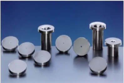
Design of orifice plate (Fig. 2.9) in jet induced attrition follows the convergent-divergent nozzle design criteria as an isentropic process. The orifice plate consists of a rounded inlet
Figure 2.9 Flow nozzles
which converges to a minimum throat and pressure recovery divergent section. Important design parameters in the convergent-divergent nozzles include stagnation ambient pressure ratio and exit to throat area ratio. Fluid flow is sonic at the throat when the Mach number is one but changes to subsonic in the divergent section. Fluid velocity does not change when critical pressure ratio (Eq. 2.21) is reached. Fig.2.10 shows how fluid temperature, pressure and velocity changes with the Mach number [102, 103]. Assuming an ideal behaviour, mass flux of a sonic flow is calculated with (Eq. 2.22).
p∗ Po = 2 k+ 1 k k−1 (2.21) G= CdAo s ( 2 k+ 1) k+1 k−1 × kM RTo (2.22)
where k is specific heat ratio, p* is downstream pressure, p
o is nozzle upstream pressure, M
is molar mass Cd is discharge coefficient.
2.7.6 Grid design
The grid is very important and its design must be carefully done to ensure smooth fluidization, prevent plugging and powder weeping into the plenum. Pressure head of solids through a fluidized bed affects resistance to fluid flow through the bed. Pressure drop (∆Pgrid) across the grid is calculated with (Eq. 2.23) [101].
The velocity through the grid is given by
Uh = Cd v u u t 2∆Pgrid ρf (2.23) Q= NUh √ ∆P ρf (2.24)
where N, Uh and dh is the number of holes, gas velocity through the hole and hole diameter respectively.
The volumetric gas flow rate is given by
Q= NUhπd
2
h
4 (2.25)
CHAPTER 3 ORGANIZATION OF THE THESIS
3.1 Original scientific hypothesis
1. Fluidized bed reactor provide an effective means of carrying out calcium looping and chemical looping combustion for post-combustion CO2due to high heat and mass
trans-fer and minimization of hot spots.
2. High fluid velocities in fluidized beds cause high frequency sorbent particle-particle and sorbent particle-reactor wall collisions. These results in momentum transfer between particles leading to mechanical degredation (attrition) of sorbent particles, production of fine particles and subsequent elutriation of fines of particular cut size.
3. Mechanical properties of sorbents are critical to their economic and environmental effectiveness.
4. High temperature requirement in Calcium looping-chemical looping combustion causes sintering of sorbent and lead to reduction in reactivity performance of sorbent.
3.2 Methodology
The project consisted three main phases.
1. The first phase involved acquisition of the various sorbents compositions and the pur-chase and installation of industrial jet attrition testing device for low temperature op-eration. The setup was then adapted to high temperature testing with the acquisition of furnace capable of heating up to 1100◦C.
2. Preliminary studies was conducted to compare the attrition resistance of CaO40CuO50Cement10
sorbent with those of two commercial catalyst: Dupont’s VPP catalyst and FCC cat-alyst.
3. Detained studies including measurement of attrition resistance of different compostions of sorbent, FCC ans VPP at vagarious process and design conditions.
3.3 Article
To realise the above objectives, a paper entitled: Attrition resistance of CaOxCuOycem1-x-y
body of the thesis). It compares the mechanical stability of Ca-based CO2 sorbents with
two commercial catalysts: DuPont’s VPP and FCC. The paper gives detailed analysis of the changes in the particles size distribution from 6 h to 96 h and 23◦C to 800◦C. A model was
![Figure 1.1 Fossil fuel related carbon dioxide emissions trend [1].](https://thumb-eu.123doks.com/thumbv2/123doknet/2323358.29613/18.918.196.730.123.492/figure-fossil-fuel-related-carbon-dioxide-emissions-trend.webp)

![Table 1.1 Choice of oxygen carrier for CH 4 fuel in CLC [16]](https://thumb-eu.123doks.com/thumbv2/123doknet/2323358.29613/23.918.216.700.154.298/table-choice-oxygen-carrier-ch-fuel-clc.webp)
![Figure 2.1 : Modes of Attrition [29] .](https://thumb-eu.123doks.com/thumbv2/123doknet/2323358.29613/27.918.223.700.121.465/figure-modes-of-attrition.webp)
![Figure 2.3 Jet cup set up [58] .](https://thumb-eu.123doks.com/thumbv2/123doknet/2323358.29613/31.918.248.490.601.984/figure-jet-cup-set-up.webp)
![Figure 2.4 Fluidization regimes [81] .](https://thumb-eu.123doks.com/thumbv2/123doknet/2323358.29613/37.918.199.735.171.464/figure-fluidization-regimes.webp)