HAL Id: hal-02982635
https://hal-mines-albi.archives-ouvertes.fr/hal-02982635
Submitted on 28 Oct 2020
HAL is a multi-disciplinary open access
archive for the deposit and dissemination of
sci-entific research documents, whether they are
pub-lished or not. The documents may come from
teaching and research institutions in France or
abroad, or from public or private research centers.
L’archive ouverte pluridisciplinaire HAL, est
destinée au dépôt et à la diffusion de documents
scientifiques de niveau recherche, publiés ou non,
émanant des établissements d’enseignement et de
recherche français ou étrangers, des laboratoires
publics ou privés.
Effect of spraying parameters on surface roughness,
deposition efficiency, and microstructure of electric arc
sprayed brass coating
Zia Arif, Masood Shah, Ehtsham Ur Rehman, Ali Tariq
To cite this version:
Zia Arif, Masood Shah, Ehtsham Ur Rehman, Ali Tariq.
Effect of spraying parameters on
surface roughness, deposition efficiency, and microstructure of electric arc sprayed brass
coat-ing. International Journal of ADVANCED AND APPLIED SCIENCES, 2020, 7 (7), pp.25 - 39.
�10.21833/ijaas.2020.07.004�. �hal-02982635�
Contents lists available at Science-Gate
International Journal of Advanced and Applied Sciences
Journal homepage: http://www.science-gate.com/IJAAS.html
25
Effect of spraying parameters on surface roughness, deposition efficiency,
and microstructure of electric arc sprayed brass coating
Zia Ullah Arif 1, 2, *,Masood Shah 1, 3, Ehtsham ur Rehman 2, 4, Ali Tariq 5
1Mechanical Engineering Department, University of Engineering and Technology, Taxila, Pakistan
2Mechanical Engineering Department, University of Management & Technology, Lahore, Pakistan
3Mechanical Engineering Department, Université de Toulouse, Albi, France
4Mechanical Engineering Department, University of Engineering and Technology, Lahore, Pakistan
5School of Mechanical & Manufacturing Engineering, National University of Sciences and Technology, Islamabad, Pakistan
A R T I C L E I N F O A B S T R A C T
Article history:
Received 29 December 2019 Received in revised form 25 March 2020
Accepted 26 March 2020
Thermal, chemical, and metallurgical surface treatment techniques are being applied to give materials the desirable properties for numerous applications in service. Nowadays, electric arc spraying of copper alloys has gained importance in surface engineering owing to their excellent mechanical properties. However, electric arc sprayed metallic coating usually has high coating roughness and low deposition efficiency upon adherence to the substrate. In this article, the brass coating was deposited onto a mild steel substrate using a twin wire arc spraying technique. The spraying parameters current, voltage, and spray off distance were varied during the deposition process. To gain an understanding, the effect of these spraying parameters on the characteristics of the coating was investigated in terms of its surface roughness, deposition efficiency, and microstructure. The primary purpose of this research is to optimize the process in terms of coating roughness and deposition efficiency. Based on the results obtained, it was observed that an increase in voltage and spray off distance resulted in an increase in coating roughness, whilst an increase in current resulted in a decrease in coating roughness. Deposition efficiency was also greatly affected by the process parameters and decreased significantly with the longer spray off distance. Furthermore, the deposition efficiency increased with the decrease in surface roughness and vice versa. The best results in terms of low coating roughness, high deposition efficiency, and optimized microstructure were found at 24V, 240A, and 100 mm. The use of small diameter feedstock, supersonic nozzle incorporated in equipment, better surface preparation, and optimized process parameters gave better results as compared to the previous study in the field of electric arc spray coating.
Keywords:
Brass coating Coating roughness Deposition efficiency Electric arc spray Spraying parameters
© 2020 The Authors. Published by IASE. This is an open access article under the CC BY-NC-ND license (http://creativecommons.org/licenses/by-nc-nd/4.0/).
1. Introduction
*Mild steel is widely used in numerous fields such
as gas pipelines, boilers, nuclear power plants, oil and gas industries, marine and food processing industries due to its excellent mechanical properties, cost, machinability, and availability. But one major disadvantage of using mild steel is that it undergoes corrosion due to the presence of oxide content and severe ambient conditions. Therefore, mild steel
* Corresponding Author.
Email Address: zia.arif@skt.umt.edu.pk (Z. U. Arif)
https://doi.org/10.21833/ijaas.2020.07.004
Corresponding author's ORCID profile:
https://orcid.org/0000-0002-9254-7606
2313-626X/© 2020 The Authors. Published by IASE. This is an open access article under the CC BY-NC-ND license (http://creativecommons.org/licenses/by-nc-nd/4.0/)
cannot be used in a corrosive environment unless it undergoes protective coating (Priyantha et al., 2003). Furthermore, components with superior characteristics are necessary for the top domains of industries. These superior characteristics materials (copper, titanium, magnesium, and their alloys) are preferred owing to their properties suitable for the high performance in a harsh environment. Surface modifications of numerous materials of inferior characteristics are of critical importance. Surface engineering is the vast and latest engineering field used to enhance functional properties such as wear-resistant, corrosion-wear-resistant, physical, electrical, magnetic and mechanical, etc. of the substrate, which may be metals, polymers or composites (Martin, 2011; Tharajak et al., 2017). Some sort of surface treatment is required to enhance all these surface properties (Chen et al., 2016). For this purpose,
26
three types of techniques are used. Thermal spraying has been gaining importance over the other coating techniques in recent times (Kang et al., 2017;
Cavallaro et al., 2017). Thermal spraying includes a variety of coating techniques such as plasma arc spray, electric arc spray (EAS), and flame spray. Out of all thermal spraying techniques, EAS coating is the oldest deposition technique invented by Max Ulrich Schoop in 1918 (Siegmann and Abert, 2013). It was only commercialized in the 1960s because of its low equipment and operational cost, high deposition rate, and thermal efficiency (Fauchais, 2015;
Fantozzi et al., 2017; Gan and Berndt, 2015). EAS, also called twin wire arc spray or wire arc spray is a deposition technique in which two electrically conductive wires with opposite polarity are fed through rollers and converge through wire guide to intersect at some point. At the point of intersection, an arc is generated at the tip of wires which shear off the wires (Gedzevičius and Valiulis, 2003). The molten particles of the wires are accelerated towards the substrate through compressed air or nitrogen gas as an atomizing gas where these particles are solidified or sintered over one another. This layer by layer solidification produces protective coating. EAS coating is a production technique commonly used for metallic coating (aluminum, copper, stainless steel, and magnesium). The metallic coating involves the coating materials of better corrosion resistance, wear resistance, hardness, and mechanical properties (Pawłowski, 2008).
Microstructure, fatigue strength, wear rate, corrosion resistance, coating porosity, hardness, toughness, deposition efficiency (DE), adhesive strength, surface roughness (SR) and oxide contents are the most significant parameters which determine the characteristics of coatings (Kumar et al., 2016;
Boronenkov and Korobov, 2016; Tillmann et al., 2008). Various parameters in thermal electric arc spraying technique which affect the quality of coating comprise the voltage, current, wire feed rate, spray off distance (SOD), nozzle geometry, (Li and Li, 2005; Wilden et al., 2005; Toma et al., 2013a; 2013b;
Matz and Aumiller, 2014) coating’s surrounding environment (inert, ambient or vacuum chamber), pressure of atomized gas, feedstock material (Mauer et al., 2017), type of atomized gas (air or nitrogen), preheating of the substrate surface or post heat treatment of coating lamellae (Chen et al., 2010;
Zhou et al., 2017) and type of surface preparation (shot blasting, sandblasting, rough threading) (Georgescu et al., 2015). The EAS coating technique produces the coating of high porosity, high oxide content, low DE, and high SR (Toma et al., 2015;
Adamiak et al., 2018; Bonabi et al., 2018). Therefore, the optimization of the EAS parameters is essential to achieve effective coatings for particular applications (Salavati et al., 2016; Hvozdets’kyi et al., 2018; Darut et al., 2015). Many researchers have examined the influence of a wide range of spraying parameters on the characteristics of the metallic coating prepared by thermal spraying techniques such as Johnston et al. (2013) reported the effect of
spraying parameters on the coating characteristics of arc sprayed zinc coating. The study found that coating characteristics such as microstructure, porosity, and hardness were proportional to the input spraying parameters. Kumar et al. (2016)
optimized the process parameters such a current, voltage, spray off distance, and gas pressure of the two-wire arc sprayed aluminum coating in terms of its desirable microstructure, physical, and mechanical properties. Afzal et al. (2015) studied the influence of SOD on the microstructure and coating thickness of the plasma sprayed cermet coatings. The study revealed the SOD range for the optimum microstructure whilst coating thickness was found at a minimum level at this spraying distance range.
Kumar and Pandey (2017) presented the paper
about the effect of plasma spraying parameters on the coating thickness and surface roughness. Optimized process parameters were found for the low surface roughness value and high coating thickness. Maledi et al. (2017) produced cold sprayed zinc coating to evaluate the influence of temperature, pressure, and spraying distance with regard to the microstructure, microhardness, and coating thickness. The study indicated that an increase in temperature resulted in an increase in microhardness whilst an increase in SOD led to a decrease in microhardness and coating thickness.
Furthermore, copper alloys, particularly brass (Cu-Zn), offer antibacterial character (Ashby and Jones, 2012), corrosion resistance, formability, and reasonably good mechanical properties. Due to this reason, brass coatings are used in a variety of physical and chemical techniques. Sharifahmadian et al. (2013) investigated the microstructure, thickness, and adhesion of the arc sprayed copper coating on the stainless steel substrate. Microscopic analysis results revealed an excellent corrosion resistant copper coating under severe ambient conditions.
Arkhipov et al. (2019) studied the effect of heat treatment at various time intervals on the brass coating deposited by cold dynamic gas spraying. The study revealed that the cohesive strength increased when the temperature was 4000C for sixty minutes.
Chen et al. (2015) prepared low-cost,
antimicrobial, and corrosion-resistant brass coating using high power impulse magnetron sputtering.
Theimer et al. (2019) presented a review report to show the effect of brass coating on the adhesion strength using a cold spraying technique. The research concluded that adhesive strength could be optimized by effective and ideal surface preparation. From the literature review, it is concluded that even though a large amount of work has been done in the field of thermal sprayed metallic coating and many researchers have also reported that control factors incorporate coating of the highest quality. However, ASR's relationship with respect to control factors has not yet been well understood with the EAS technique. Thus, a clear gap in knowledge exists. In this research, an attempt was made for the development of EAS coating for industrial applications. The research is focused on
27
understanding the effect of spraying parameters (spray distance, voltage, and current) on the ASR, DE, and microstructure of the brass coatings. The aim of the present work is intended to optimize spraying parameters of EAS in an attempt to control DE and coating roughness. The substrate has been chosen, keeping in view its vast applications in the industries. The results originated from this investigation will be helpful to explore the possibility of the use of EAS coatings on industrial materials so as to attain high DE and low ASR value of the so formed coatings.
2. Experimental procedure
2.1. Feedstock and substrate material
In this experiment, commercially available brass wire with 1.2 mm in diameter was supplied by Sulzer-Metco Inc. (Westbury, New York, USA). The
substrate used for coating was mild steel A106 grade B of composition tabulated in Table 1.
2.2. Arc spraying parameters
Two control parameters with four levels [minimum (level 1), medium (level 2, level 3) and maximum (level 4)] and one control parameter with two levels [minimum (level 1), maximum (level 2)] are considered to evaluate the effect of each factor. The main spraying parameters (voltage, current, and SOD) and experimental settings are presented in
Table 2.
In addition to this, compressed air used as primary gas with a pressure of 5 bar and spray angle was kept at 900. The selected spraying parameters
permutations are summarized in Table 3. The second set of coating parameters were produced by varying SOD. This additional spraying parameter is selected in an attempt to evaluate the effect of SOD on the ASR and DE.
Table 1: Chemical composition of mild steel used as a substrate
Elements C Mn S P Si Ni Cu Cr V Mo
Composition 0.3 0.29 0.035 0.035 0.1 0.4 0.4 0.4 0.08 0.15
Table 2: Process parameters and their corresponding level
Process parameter Range 1 2 Level 3 4
Voltage (V) 24-36 24 28 32 36
Current (A) 150-240 150 180 210 240
SOD (mm) 100-120 100 120 - -
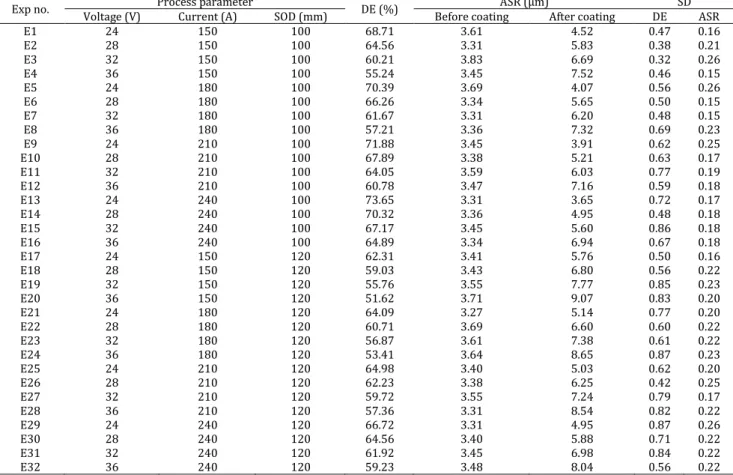
Table 3: Summary of the experimental layout (design matrix) and results of DE and ASR
Exp no. Voltage (V) Process parameter Current (A) SOD (mm) DE (%) Before coating ASR (μm) After coating DE SD ASR
E1 24 150 100 68.71 3.61 4.52 0.47 0.16 E2 28 150 100 64.56 3.31 5.83 0.38 0.21 E3 32 150 100 60.21 3.83 6.69 0.32 0.26 E4 36 150 100 55.24 3.45 7.52 0.46 0.15 E5 24 180 100 70.39 3.69 4.07 0.56 0.26 E6 28 180 100 66.26 3.34 5.65 0.50 0.15 E7 32 180 100 61.67 3.31 6.20 0.48 0.15 E8 36 180 100 57.21 3.36 7.32 0.69 0.23 E9 24 210 100 71.88 3.45 3.91 0.62 0.25 E10 28 210 100 67.89 3.38 5.21 0.63 0.17 E11 32 210 100 64.05 3.59 6.03 0.77 0.19 E12 36 210 100 60.78 3.47 7.16 0.59 0.18 E13 24 240 100 73.65 3.31 3.65 0.72 0.17 E14 28 240 100 70.32 3.36 4.95 0.48 0.18 E15 32 240 100 67.17 3.45 5.60 0.86 0.18 E16 36 240 100 64.89 3.34 6.94 0.67 0.18 E17 24 150 120 62.31 3.41 5.76 0.50 0.16 E18 28 150 120 59.03 3.43 6.80 0.56 0.22 E19 32 150 120 55.76 3.55 7.77 0.85 0.23 E20 36 150 120 51.62 3.71 9.07 0.83 0.20 E21 24 180 120 64.09 3.27 5.14 0.77 0.20 E22 28 180 120 60.71 3.69 6.60 0.60 0.22 E23 32 180 120 56.87 3.61 7.38 0.61 0.22 E24 36 180 120 53.41 3.64 8.65 0.87 0.23 E25 24 210 120 64.98 3.40 5.03 0.62 0.20 E26 28 210 120 62.23 3.38 6.25 0.42 0.25 E27 32 210 120 59.72 3.55 7.24 0.79 0.17 E28 36 210 120 57.36 3.31 8.54 0.82 0.22 E29 24 240 120 66.72 3.31 4.95 0.87 0.26 E30 28 240 120 64.56 3.40 5.88 0.71 0.22 E31 32 240 120 61.92 3.45 6.98 0.84 0.22 E32 36 240 120 59.23 3.48 8.04 0.56 0.22
28
2.3. Substrate preparation
Prior to the EAS coating, the substrates flat mild steel A106 grade B of dimension 50mm × 40mm × 4mm were degreased, and grit blasted at room temperature with Metco Lite Alumina grit (Sulzer Metco, USA) at 4.5 bar (65psi) pressure, 7.5 cm (3 in) standoff distance and 45° angle of attack. The grit blasting enhances the coating adhesion by virtue of strong mechanical interlocking. After grit blasting, the samples were cleaned with acetone and dried by using an air dryer. The coating was deposited by using supersonic arc spraying equipment SX-400 (Guangzhou Sanxin Metal SandT Co. Ltd, China). The spraying gun contains a de Laval nozzle.
Each sample was weighed before and after coating, using a Kern electronic scale with an accuracy of 0.01 g, to compute the mass of deposited material and DE. The feedstock brass wire was also weighed after the coating of each sample to calculate the mass of the feedstock wire used. In order to minimize damage, the coated samples were cut into a dimension of 20mm × 20mm on wire cut electric discharge machine (EDM) for microscopic analysis. The operating parameters of the EDM wire cut machine were frequency voltage=80V, high-frequency current=1A, and drive voltage=28V. The samples after cutting were cleaned with acetone.
The samples for microscopic analysis were prepared by performing standard metallographic techniques. To study the cross-sections, the samples were mounted in epoxy and cured for two days. One side of all these specimens was ground and polished with sequential mechanical media 6-microns and 3-microns diamond pastes. This technique provided a quality surface. The samples were etched to reveal details of the lamellar microstructure. Therefore, 2% Nital (2ml HNO3 and 98ml ethanol) solution was
used for the etching of mild steel while etchant (125ml HNO3 and 125ml distilled water) used for
brass.
2.4. Coating characterization
The average substrate roughness of Ra of each
sample was measured before and after the coating by using surface roughness tester (China made, Model NDT-110 with a resolution of 0.05 μm and maximum measuring range of 10 μm). Five measurements of each coated sample were performed at random locations to ensure repeatability of results and minimize error. The surface roughness values were analyzed to evaluate the effect of different spraying parameters. The DE of brass was calculated by computing the mass of deposited material and mass of the feedstock wire. DE is also an arithmetic mean of five measurements. The cross-sectional morphology of the brass coating was evaluated by using an optical microscope Olympus BX51. The microscopic analysis was performed across the cross-sections of the coatings.
Only a subset of data was chosen for microscopic cross-sectional analysis.
3. Results and discussions
The spraying parameters have a distinct influence on coating characteristics. The experimental investigations show significant changes in ASR, DE, and microstructure when varying the input parameters. The expectation of this experiment is to improve overall ASR and DE. In the following, the results are described and discussed in detail.
3.1. ASR of the EAS brass coating
Surface roughness is one of the most significant factors which determine the characteristics of the coating. It is basically of two types. For example, micro surface roughness and macro surface roughness. Micro surface roughness affects the mechanical behavior of the coating. The values of ASR in terms of arithmetic mean are tabulated in
Table 3.
The EAS coating usually depicts the inhomogeneous surface roughness profile that depends upon the spraying parameters (current, voltage, and spray distance). It is suggested that the threshold substrate roughness of about 3.5 μm is required for better metallic EAS deposition (Georgescu et al., 2015). As the process parameters during grit blasting were constant for all samples, the ASR values of all the samples after grit blasting were almost the same as presented in Table 3. But there is rather an increase in ASR after coating. This increase in ASR values purely depends on the process parameters.
3.1.1. Effect of voltage on the ASR
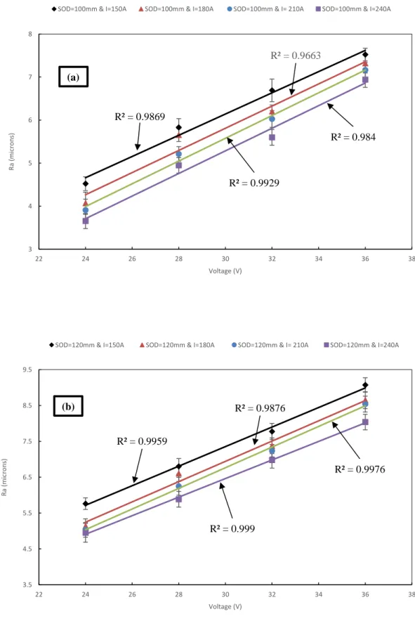
The ASR subjected to great variation with respect to change in voltage level. The mathematical fits of data with linear function yield determination coefficients of R2 higher than 0.96 in Fig. 1.
Fig. 1a shows that as the voltage level rises from 24V to 36V at 150A and 100mm, the ASR rises about sixty-six percent up to 7.50 microns. At 240A and 100mm for the same voltage increase, the ASR increases about ninety percent up to 6.94 microns. Likewise, in Fig. 1b as the voltage increases from 24V to 36V, at 150A and 120mm, the ASR increases about fifty-eight percent up to 9.07 microns. While an increase in ASR at 240A and 120mm is about sixty-three percent up to 8.04 microns. This behavior clearly shows that the coating roughness depends on the particle size, and in turn, particle size depends on the voltage significantly. As previously reported by
Tillmann et al. (2008) and Wilden et al. (2007) that particle size is bigger at high voltages. Hence, larger particles result in fewer spheroids particles and a more lamellar structure. These large particles delaminate upon impact, increase the ASR value of the EAS coating.
29
Fig. 1: Variation in coating roughness with respect to voltage (a) At SOD=100mm (b) At SOD=120mm. Straight lines
represent the linear curve fits
3.1.2. Effect of arc current on the ASR
The effect of current on the ASR shows completely opposite behavior as that of voltage. The linear curve fits obtained from this formulation indicates linear negative behavior with
determination coefficients of R2 of values higher than 0.95 except one. Fig. 2 illustrate the effect of current on the ASR.
The ASR decreases by increasing current from 150A to 240A for all cases. By increasing the current level at a lower voltage and higher SOD results in
3 4 5 6 7 8 22 24 26 28 30 32 34 36 38 R a ( m ic ro n s) Voltage (V)
SOD=100mm & I=150A SOD=100mm & I=180A SOD=100mm & I= 210A SOD=100mm & I=240A
(a) R² = 0.9869 R² = 0.9663 R² = 0.9929 R² = 0.984 3.5 4.5 5.5 6.5 7.5 8.5 9.5 22 24 26 28 30 32 34 36 38 R a ( m ic ro n s) Voltage (V)
SOD=120mm & I=150A SOD=120mm & I=180A SOD=120mm & I= 210A SOD=120mm & I=240A
(b) R² = 0.9876
R² = 0.9959
R² = 0.9976
30
more decrease of ASR as indicated by the slope of the line in Fig 2b. The decrease in surface roughness could also be attributed to particle size. By increasing the current level at fixed voltage and SOD has decreased the particle size (Tillmann et al., 2008;
Wilden et al., 2007). Small particles of low viscosity
associated with an increase in current provide lamellar structure and generate smoother surface upon impact. The graph lines in Fig. 2a, and Fig. 2b
are less steep for current than voltages. It shows that this spraying parameter has a lesser effect on the ASR of the arc sprayed coating.
Fig. 2: Influence of arc sprayed current on the ASR of the coating (a) At SOD=100mm (b) At SOD=120mm
3 4 5 6 7 8 120 150 180 210 240 270 R a ( m ic ro n s) Current (A)
SOD=100mm & V=24V SOD=100mm & V=28V SOD=100mm & V=32V
SOD=100mm & V=36V Linear (SOD=100mm & V=24V) Linear (SOD=100mm & V=32V)
Linear (SOD=100mm & V=36V)
(a) R² = 0.9962 R² = 0.9712 R² = 0.9754 R² = 0.9561 3 4 5 6 7 8 9 10 120 150 180 210 240 270 R a ( m ic ro n s) Current (A)
SOD=120mm & V=24V SOD=120mm & V=28V SOD=120mm & V=32V
SOD=120mm & V=36V Linear (SOD=120mm & V=24V) Linear (SOD=120mm & V=28V)
Linear (SOD=120mm & V=32V) Linear (SOD=120mm & V=36V)
(b)
R² = 0.7909 R² = 0.9712
R² = 0.984
31
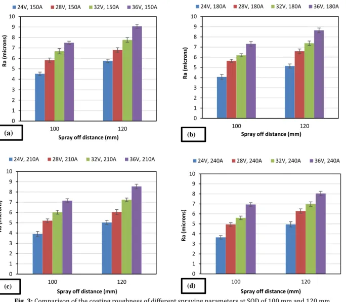
3.1.3. Effect of SOD on the ASR
The SOD was initially set at 100 mm and then increased to a distance of 120 mm. From the spreadsheet diagram (Fig. 3), clear tendencies could be ascertained. At first, SOD has a high influence on ASR. The error bars depict the standard deviation (SD) of five measurements. In Fig. 3a as the SOD increases from 100mm to 120mm at 150A and 24V, and the ASR increases about twenty-eight percent up to 5.76 microns. In Fig 3b for the same SOD increase at 180A and 24V, the ASR increases about twenty-six percent up to 5.14 microns. Similarly, in Fig. 3c as the SOD increases from 100mm to 120mm at 210A
and 24V, the ASR increases about twenty-nine percent up to 5.03 microns. While in Fig. 3d increase in ASR with the increase in SOD at 240A and voltage 24V is about thirty-six percent up to 4.95 microns. This type of variation in ASR with respect to SOD indicates that slower particle speed associated with longer SOD results in less deformation upon impact (Maledi et al., 2017). Furthermore, the atomized particles delaminate more significantly upon impact for longer SOD. Thus, it yields a rougher surface. In addition to this, the density of the particles increases with an increase in SOD. This increase in SOD also results in a drastic loss of particle temperature.
Fig. 3: Comparison of the coating roughness of different spraying parameters at SOD of 100 mm and 120 mm 3.1.4. Cumulative effect of voltage, arc current,
and SOD on the ASR value
Among the coating samples, the coating roughness was observed lowest at 24V, 240A, and 100mm. It shows that the temperature of the melting wire usually decreases by adjusting the voltage at low and current at a high level. This may be due to the increase in arc current, which directly activates a higher feed rate of wire. As a result, melted volume increases at the wire tips. Thus, the temperature of the particles and arc length is decreased. Only small
molten droplets with low viscosity sheared off from the tips of the wires and accelerated towards the substrate. As a result, it generates a smoother surface upon impact. Hence, ASR decreases at a high level of current and low voltage. On the other hand, high voltage and low current levels ensure that high arc energy is used to acquire high temperatures at the tips of the wires. Due to this, large molten particles with high viscosity are impacted on the substrate and delaminate. Thus, it yields a rougher surface and increases ASR. Due to this reason, ASR was maximum at 36V, 150A, and 120mm.From all
0 1 2 3 4 5 6 7 8 9 10 100 120 R a (m icr ons )
Spray off distance (mm)
24V, 240A 28V, 240A 32V, 240A 36V, 240A
(d) 0 1 2 3 4 5 6 7 8 9 10 100 120 R a (m icr ons )
Spray off distance (mm)
24V, 210A 28V, 210A 32V, 210A 36V, 210A
(c) 0 1 2 3 4 5 6 7 8 9 10 100 120 R a (m icr ons )
Spray off distance (mm)
24V, 180A 28V, 180A 32V, 180A 36V, 180A
(b) 0 1 2 3 4 5 6 7 8 9 10 100 120 R a (m icr ons )
Spray off distance (mm)
24V, 150A 28V, 150A 32V, 150A 36V, 150A
32
the above discussion, it is evident that ASR is more affected by voltage and SOD as compared to current. Overall, ASR produced by the feedstock brass wire 1.2 mm in diameter is less than previously described by Wilden et al. (2007) and Rokni et al. (2017). Because EAS coating of brass is different, by soft particles hitting a harder, less deformable substrate produces the surface of low ASR value.
3.2. DE of the EAS coating
DE of the electric arc sprayed coating is defined as the ratio of the deposited mass of the coating to the total mass of the feedstock material.
𝜂𝐷𝐸=
𝑚𝑑𝑒𝑝𝑜𝑠𝑖𝑡𝑒𝑑
𝑚𝑓𝑒𝑒𝑑𝑠𝑡𝑜𝑐𝑘 (1)
DE was measured by finding the difference in the weight of the coupon before and after the coating divided by the weight of the feedstock wire sprayed. The DE of all the brass arc sprayed coating samples is tabulated in Table 3. The results showed that DE was affected by all the spraying parameters.
3.2.1. Effect of voltage on the DE
The regression analysis of linear models shows the determination coefficient R2 of values higher than 0.98 with a negative relationship. Fig. 4 depicts the variation in the DE of the arc sprayed brass coating with the change in voltage when current and SOD is constant. A rise in the voltage level from 24V to 36V causes an increase in the arc length and enthalpy of the molten metal droplets. This leads to an increase in metal burnout (Boronenkov and Korobov, 2016). As a result, DE is decreasing. In addition to this, as the voltage increases, the particle size gets bigger. As mentioned before, these large particles upon impact increase ASR. The following atomized particles delaminate upon impact and reduce DE. The maximum percentage decrease in DE was measured at 240A, 120mm, and when voltages level changes from 24V to 36V.
3.2.2. Effect of arc current on the DE
The linear model for DE as a function of the current correlates well with determination coefficient R2 of values larger than 0.97, as shown in
Fig. 5. The variation in the DE of the coating with a variety of arc current is demonstrated in Fig. 5. The heat content of the droplets increases with an increase in the current level. This leads to better chemical and physical interaction between the droplets and substrate at the moment of impact (Boronenkov and Korobov, 2016). As a result, DE increases. In addition to this, as the current increases, the DE increases due to the decrease in the particle size. These small atomized particles provide good mechanical interlocking between the lamellae.
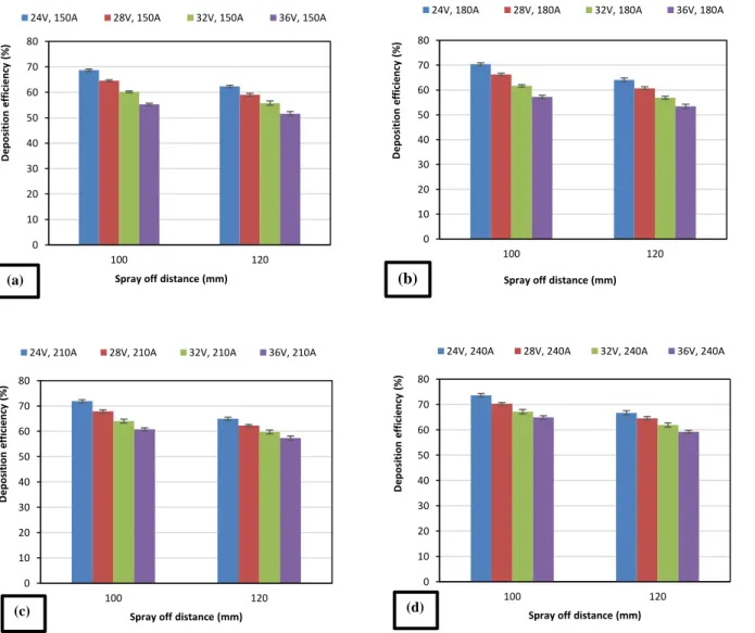
3.2.3. Effect of SOD on the DE
Spreadsheet diagram (Fig. 6) illustrates that a change of SOD also significantly influences the coating buildup. As the SOD increases from 100mm to 120mm, the particle temperature as well as velocity decreases, which would result in less cohesion within the lamellar structure. As a result, DE decreases.
3.2.4. Cumulative effect of voltage, arc current, and SOD on the DE
The DE varies from 51.62% to 73.65% within the investigated scope of the process parameters. In general, with the increase in SOD, voltage, and decrease in current, the DE decreases, and vice versa. The DE was maximum at 24V, 240A, and 100mm and reached its minimum value at 36V, 150A, and 120mm. It can be related to the ASR of the coating. Low voltage, high current, and small SOD result in high particle velocity and small particle size, which gives a lower value of ASR (3.65 microns). These smaller particles provide better mechanical interlocking between the splats and also on the substrate surface. Thus, DE is maximum at these spraying parameters. Large particle size may occur with a decrease in voltage and an increase in current. In addition to this, with the increase in SOD, inflight molten droplets may undergo oxidation as well as quickly solidified during their flight. Due to the solidification of the particles during their flight, the following atomized particles may not adhere to the coating. As a result, the DE of the coating decreases.
It is evident from Fig. 5 that current lines are less steep than voltage lines presented in Fig. 4. Hence, DE is least affected by the arc current as. In this experiment, DE shows the relatively improved behavior for metallic EAS compared to that reported by Rokni et al. (2017) previously. Supersonic equipment and brass wire small in diameter helped to achieve overall higher deposition efficiencies. This may also be explained due to viscoelasticity, ductility, thermal conductivity, and wetting ability of brass.
3.3. Dependence of DE on ASR value
The relationship between ASR and DE is plotted, as shown in Fig. 7 by taking the values of all the samples. Linear curve fitting is applied to this formulation, and the determination coefficient R2 is
higher than 0.88, as shown in Fig. 7. The results depicted that the DE of EAS coating decreased with an increase in the ASR. An increase in coating roughness causes splashing and delamination of the molten metal droplets, as previously reported by
Boronenkov and Korobov (2016). Hence, DE reduces
with an increase in coating roughness. This obtained results of EAS coating are perfectly in line with as previously reported (Singh et al., 2017; Lima et al., 2002) for other thermal spraying techniques.
33
Fig. 4: Percentage variation in DE of the coating due to change in the voltage (a) At SOD=100mm (b) At SOD=120mm
50 60 70 80 22 24 26 28 30 32 34 36 38 D ep o si ti o n E ff ic ien cy ( % ) Voltage (V)
SOD=100mm & I=150A SOD=100mm & I=180A SOD=100mm & I= 210A
SOD=100mm & I=240A Linear (SOD=100mm & I=150A) Linear (SOD=100mm & I=180A )
Linear (SOD=100mm & I= 210A) Linear (SOD=100mm & I=240A)
(a) R² = 0.9931 R² = 0.998 R² = 0.9995 R² = 0.9982 50 55 60 65 70 22 24 26 28 30 32 34 36 38 D ep o si ti o n E ff ic ien cy ( % ) Voltage (V)
SOD=120mm & I=150A SOD=120mm & I=180A SOD=120mm & I= 210A
SOD=120mm & I=240A Linear (SOD=120mm & I=150A) Linear (SOD=120mm & I=180A )
Linear (SOD=120mm & I= 210A) Linear (SOD=120mm & I=240A)
(b)
R² = 0.9989
R² = 0.9975
R² = 0.9994
34
Fig. 5: Variation in DE of the coating with respect to arc current (a) At SOD=100mm (b) At SOD=120mm 3.4. Cross-sectional morphology of EAS coating
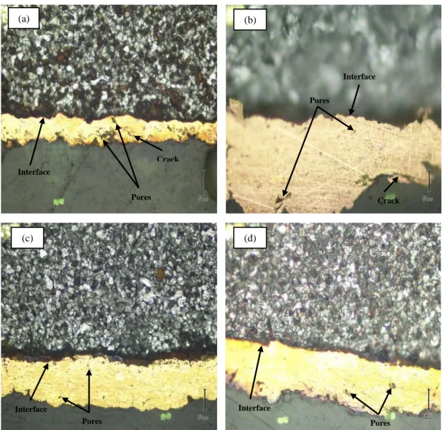
The morphologies of the brass deposited coating on the mild steel substrate at various process parameters were evaluated by an optical microscope. The microstructure of the EAS coating has an abundance of defects and imperfections. These imperfections depend on the spray parameters and type of feedstock material used.
Besides their influence on the ASR and DE, the spraying parameters have significant effects on the microstructure of arc sprayed brass coating. Fig. 8
and Fig. 9 show the typical cross-sectional
micrograph of the arc sprayed specimens under various spraying conditions. The etched surface of mild steel exhibits smooth and fine scratch lines, but brass deposited coating contains pores and cracks. The micrograph of all samples showed that it mainly
50 60 70 80 120 150 180 210 240 270 D ep o si ti o n E ff ic ien cy ( % ) Current (A)
SOD=100mm & V=24V SOD=100mm & V=28V SOD=100mm & V=32V
SOD=100mm & V=36V Linear (SOD=100mm & V=24V) Linear (SOD=100mm & V=28V)
Linear (SOD=100mm & V=32V) Linear (SOD=100mm & V=36V)
(a) R² = 0.9991 R² = 0.991 R² = 0.9749 R² = 0.9779 50 55 60 65 70 120 150 180 210 240 270 D ep o si ti o n E ff ic ien cy ( % ) Current (A)
SOD=120mm & V=24V SOD=120mm & V=28V SOD=120mm & V=32V
SOD=120mm & V=36V Linear (SOD=120mm & V=24V) Linear (SOD=120mm & V=28V)
Linear (SOD=120mm & V=32V) Linear (SOD=120mm & V=36V)
(b)
R² = 0.9848 R² = 0.9908
R² = 0.9748
35
consists of lamellar splats contains pores and cracks. A coarse cross-sectional microstructure due to poor atomization of the molten particles was presented in
Fig. 8a. The microstructure also showed pores and oval like voids near the coating interface. There were also “cracklike” pores that show their presence within the lamellae structure. The formation of cracks between the lamellae is due to the oxidation of the inflight molten particles (Toma et al., 2015). The presence of pores and cracks within the coating layer itself indicates that a relatively poor cohesion between the coating splats may exist.
Fig. 8b reveals a relatively better coating microstructure, but there were also round voids and pores near the interface zone. Fig. 8c presents relatively densified microstructure with no coarse pores nor micro-cracks and adhering well due to strong interlocking between them. It is evident that the layers bond to the substrate without any distinctive irregular interface. In Fig. 8d the typical morphology of the electric arc sprayed coating depicted much finer microstructure due to good atomization. There was no crack at the coating interface, which depicts the good coating interface and adhesiveness with splats perfectly locked onto
the surface irregularities of the substrate. As mentioned above, particle size depends on the voltage and arc current significantly. This can be ascertained in the microstructure of the coating, too. Low voltage makes particle size smaller, and high current allows the spray particles to increase temperature melting their full (Wilden et al., 2007). This results in a fine microstructure, as presented in
Fig. 8b and Fig. 8c.
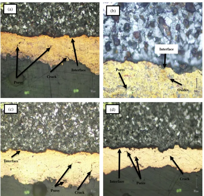
Fig. 9a exhibits round, and oval like pores indicate poor mechanical interlocking exist between the coating splats. There were dark regions at the coating interface indicates that either the substrate surface was contaminated prior to the arc sprayed coating or splats undergoes faster rate of cooling on the surface of the substrate initially provided higher chances for the formation of unfused splats (Hvozdets’kyi et al., 2018). Fig. 9b depicts pores and oxide content in the coating structure. The oxide contents are either formed during the flight of the molten droplets or during the cooling of splats upon adherence with the substrate (Adamiak et al., 2018;
Salavati et al., 2016).
Fig. 6: Percentage change in DE of the coating of different spraying parameters at SOD of 100 mm and 120 mm
0 10 20 30 40 50 60 70 80 100 120 D e po si ti o n ef fi ci e nc y (% )
Spray off distance (mm)
24V, 240A 28V, 240A 32V, 240A 36V, 240A
(d) 0 10 20 30 40 50 60 70 80 100 120 D ep o si ti o n e ff ic ie n cy (% )
Spray off distance (mm)
24V, 210A 28V, 210A 32V, 210A 36V, 210A
(c) 0 10 20 30 40 50 60 70 80 100 120 D e po si ti o n e ff ic ie nc y (% )
Spray off distance (mm)
24V, 180A 28V, 180A 32V, 180A 36V, 180A
(b) 0 10 20 30 40 50 60 70 80 100 120 D e po si ti o n e ff ic ie nc y (% )
Spray off distance (mm)
24V, 150A 28V, 150A 32V, 150A 36V, 150A
36
Fig. 7: Correlation between the ASR and DE of the arc-sprayed brass coating. The negative linear relationship between ASR
and DE can be seen here
Fig. 8: Optical micrograph of cross-sections of the EAS coatings (a) At 24V, 150A, 100mm (b) At 24V, 210A, 100mm (c) At
24V, 240A, 100mm (d) At 32V, 240A, 100mm 3 4 5 6 7 8 9 10 50 55 60 65 70 75 C o ati ng r o ug hn e ss (m ic ro ns ) Deposition efficiency (%) R² = 0.8847 R= -0.9406
Trend line
Interface Pores Crack (a) Interface Pores Crack (b) Interface Pores (c) Interface Pores (d)37
The formation of oxides could be attributed to the use of compressed air as a carrier gas. Fig. 9c and Fig. 9d present that cracks and pores were appeared between the splats as well as within coating lamellae. It indicates that both cohesive and adhesive forces are lower due to which cracks and pores may appear. It can be clearly seen from the microstructure appeared in Fig. 9 that as the SOD increases, there is a drastic loss of temperature and particle velocity. As a result, particles with less velocity and less temperature adhere to the substrate surface. Thus, cracks appear near the interface region. Moreover, as the SOD increases, inflight particles become more oxidized, which reduces cohesion between layers (Maledi et al.,
2017). Consequently, coating produced with longer SOD shows larger proportions of oxides as well as a higher amount of cracks due to lack of interlamellar adhesion.
4. Conclusion
The influence of spraying parameters (current, voltage, and SOD) on the characteristics of brass coatings deposited on the mild steel substrate was investigated. All investigated spraying parameters had a distinct effect on the ASR and DE. The following are the conclusions drawn from the results:
Fig. 9: Optical micrograph of the cross-sections of the EAS coatings (a) At 24V, 150A, 120mm (b) At 24V, 210A, 120mm (c) At
24V, 240A, 120mm (d) At 32V, 240A, 120mm The results indicated that the surface roughness of
the EAS coating had a strong relationship with the process parameters. The surface roughness of the arc sprayed coating increased with the increase in voltage and SOD. But surface roughness decreased with an increase in arc current. The factor which
effect ASR the most was voltage. The occurrence of ASR was low for the 13th spraying experiment.
All the results showed that DE was also strongly affected by different spraying parameters, the same as ASR. The DE varies inversely as a function of voltage and SOD but directly as a function of current. Furthermore, DE significantly decreases
Interface
Pores Crack
(c)
Interface Pores Crack
(d) Interface Pores Crack (a) Interface Oxides Pores (b)
38
due to longer SOD. The maximum DE 73.65% was obtained at the 13th spraying experiment within
the investigated scope of the spraying parameters.
The DE of the arc sprayed coating decreased with the increase in ASR and vice versa. The best results comprised of low ASR and high DE were found at 13th spraying parameters for all the investigated
EAS coatings.
Low ASR and high DE were observed in this work as compared to previous results found in literature due to the use of feedstock wire of brass material small in diameter.
It is concluded that SOD exhibited a drastic change in the microstructure of the coatings. Longer SOD resulted in the oxidation of inflight molten particles and also solidification of the molten particles during its flight. Due to this, cracks and pores were formed between the substrate and coating as well as between the lamellae. The finer microstructure with fewer pores and cracks were obtained due to good atomization of the molten particles at the 13th
spraying experiment from all the investigated coatings.
Hence, for any type of application of electric arc sprayed coating, optimized process parameters must be used to achieve better characteristics of the coating.
Acknowledgment
We would like to show our gratitude to the dean and principle of USPCAS-E NUST Prof. Dr Zuhair S. Khan for providing all possible help during this research process.
List of symbols
𝜂𝐷𝐸 Deposition efficiency
𝑚𝑑𝑒𝑝𝑜𝑠𝑖𝑡𝑒𝑑 Mass of the deposited material
𝑚𝑓𝑒𝑒𝑑𝑠𝑡𝑜𝑐𝑘 Mass of the feedstock material Compliance with ethical standards
Conflict of interest
The authors declare that they have no conflict of interest.
References
Adamiak M, Czupryński A, Kopyść A, Monica Z, Olender M, and Gwiazda A (2018). The properties of arc-sprayed aluminum coatings on armor-grade steel. Metals, 8(2): 142-150.
https://doi.org/10.3390/met8020142
Afzal M, Ahmed F, Khan AN, Anwar MY, Ali L, and Ajmal M (2015). Physical chemistry of WC-12% Co coatings deposited by thermal spraying at different standoff distances. International Journal of Materials Research, 106(9): 988-995.
https://doi.org/10.3139/146.111259
Arkhipov VE, Londarsky AF, Moskvitin GV, and Pugachev MS (2019). The structure and properties of the coating based on particles of copper and zinc deposited by gas-dynamic spraying. IOP Conference Series: Materials Science and
Engineering, IOP Publishing, 489(1): 012011.
https://doi.org/10.1088/1757-899X/489/1/012011 Ashby MF and Jones DRH (2012). Engineering materials 1: An
introduction to properties, applications and design. Volume 1, Elsevier, Amsterdam, Netherlands.
Bonabi SF, Ashrafizadeh F, Sanati A, and Nahvi SM (2018). Structure and corrosion behavior of arc-sprayed Zn-Al coatings on ductile iron substrate. Journal of Thermal Spray Technology, 27(3): 524-537.
https://doi.org/10.1007/s11666-018-0694-2
Boronenkov V and Korobov Y (2016). Fundamentals of arc spraying: Physical and chemical regularities. Springer, Cham, Switzerland.
https://doi.org/10.1007/978-3-319-22306-3
Cavallaro GF, Francavilla A, Latour M, Piluso V, and Rizzano G (2017). Experimental behaviour of innovative thermal spray coating materials for FREEDAM joints. Composites Part B: Engineering, 115: 289-299.
https://doi.org/10.1016/j.compositesb.2016.09.075
Chen TC, Chou CC, Yung TY, Tsai KC, and Huang JY (2016). Wear behavior of thermally sprayed Zn/15Al, Al and Inconel 625 coatings on carbon steel. Surface and Coatings Technology, 303: 78-85.
https://doi.org/10.1016/j.surfcoat.2016.03.095
Chen YH, Wu GW, and He JL (2015). Antimicrobial brass coatings prepared on poly (ethylene terephthalate) textile by high power impulse magnetron sputtering. Materials Science and Engineering: C, 48: 41-47.
https://doi.org/10.1016/j.msec.2014.11.017 PMid:25579894
Chen YX, Liang XB, Liu Y, Wei SC, and Xu BS (2010). Effect of heat treatment on microstructure and residual stress of wire arc sprayed high carbon steel coating. Surface Engineering, 26(6): 407-412.
https://doi.org/10.1179/174329409X438970
Darut G, Liao H, Coddet C, Bordes JM, and Diaby M (2015). Steel coating application for engine block bores by plasma transferred wire arc spraying process. Surface and Coatings Technology, 268: 115-122.
https://doi.org/10.1016/j.surfcoat.2014.11.018
Fantozzi D, Matikainen V, Uusitalo M, Koivuluoto H, and Vuoristo P (2017). Chlorine-induced high temperature corrosion of Inconel 625 sprayed coatings deposited with different thermal spray techniques. Surface and Coatings Technology, 318: 233-243.
https://doi.org/10.1016/j.surfcoat.2016.12.086
Fauchais P (2015). Current status and future directions of thermal spray coatings and techniques, future development of thermal spray coatings. Woodhead Publishing, Sawston, UK.
https://doi.org/10.1016/B978-0-85709-769-9.00002-6
Gan JA and Berndt CC (2015). Thermal spray forming of titanium and its alloys. In: Qian M and Froes FH (Eds.), Titanium powder metallurgy: Science, technology and applications: 425-446. Butterworth-Heinemann, Oxford, UK.
https://doi.org/10.1016/B978-0-12-800054-0.00023-X
Gedzevičius I and Valiulis AV (2003). Influence of the particles velocity on the arc spraying coating adhesion. Materials Science, 9: 334-337.
Georgescu IS, Genes C, Costache C, Baciu ER, Baciu C, and Arghirescu A (2015). Considerations regarding sandblasting metal surfaces designed for electric arc spraying. Key Engineering Materials, 660: 57-61.
https://doi.org/10.4028/www.scientific.net/KEM.660.57
Hvozdets’kyi VМ, Sirak YY, Zadorozhna KR, and Dem’yanchuk YМ (2018). Influence of the size of drops and the velocity of flow on the structure and properties of electric-arc coatings. Materials Science, 53(5): 702-708.
39 Johnston AL, Hall AC, and McCloskey JF (2013). Effect of process
inputs on coating properties in the twin-wire arc zinc process. Journal of Thermal Spray Technology, 22(6): 856-863.
https://doi.org/10.1007/s11666-013-9949-0
Kang AS, Grewal JS, and Cheema GS (2017). Effect of thermal spray coatings on wear behavior of high tensile steel applicable for tiller blades. Materials Today: Proceedings, 4(2): 95-103.
https://doi.org/10.1016/j.matpr.2017.01.001
Kumar D and Pandey KN (2017). Optimization of the process parameters in generic thermal barrier coatings using the Taguchi method and grey relational analysis. Journal of Materials: Design and Applications, 231(7): 600-610.
https://doi.org/10.1177/1464420715602727
Kumar D, Murtaza Q, and Singh RC (2016). Sliding wear behavior of aluminum alloy coating prepared by two-wire electric arc spray process. The International Journal of Advanced Manufacturing Technology, 85(1-4): 237-252.
https://doi.org/10.1007/s00170-015-7920-6
Li WY and Li CJ (2005). Optimal design of a novel cold spray gun nozzle at a limited space. Journal of Thermal Spray Technology, 14(3): 391-396.
https://doi.org/10.1361/105996305X59404
Lima RS, Kucuk A, Berndt CC, Karthikeyan J, Kay CM, and Lindemann J (2002). Deposition efficiency, mechanical properties and coating roughness in cold-sprayed titanium. Journal of Materials Science Letters, 21(21): 1687-1689.
https://doi.org/10.1023/A:1020833011448
Maledi NB, Oladijo OP, Botef I, Ntsoane TP, Madiseng A, and Moloisane L (2017). Influence of cold spray parameters on the microstructures and residual stress of Zn coatings sprayed on mild steel. Surface and Coatings Technology, 318: 106-113.
https://doi.org/10.1016/j.surfcoat.2017.03.062
Martin P (2011). Introduction to surface engineering and functionally engineered materials. Volume 74, John Wiley and Sons, Hoboken, USA.
https://doi.org/10.1002/9781118171899
Matz MM and Aumiller M (2014). Practical comparison of cylindrical nozzle and de Laval nozzle for wire arc spraying. Journal of Thermal Spray Technology, 23(8): 1470-1477.
https://doi.org/10.1007/s11666-014-0156-4
Mauer G, Sebold D, Vaßen R, Hejrani E, Naumenko D, and Quadakkers WJ (2017). Impact of processing conditions and feedstock characteristics on thermally sprayed MCrAlY bondcoat properties. Surface and Coatings Technology, 318: 114-121.
https://doi.org/10.1016/j.surfcoat.2016.08.079
Priyantha N, Jayaweera P, Sanjurjo A, Lau K, Lu F, and Krist K (2003). Corrosion-resistant metallic coatings for applications in highly aggressive environments. Surface and Coatings Technology, 163: 31-36.
https://doi.org/10.1016/S0257-8972(02)00590-X
Rokni MR, Nutt SR, Widener CA, Champagne VK, and Hrabe RH (2017). Review of relationship between particle deformation, coating microstructure, and properties in high-pressure cold spray. Journal of Thermal Spray Technology, 26(6): 1308-1355.
https://doi.org/10.1007/s11666-017-0575-0
Salavati S, Coyle TW, and Mostaghimi J (2016). Twin wire arc spray process modification for production of porous metallic
coatings. Surface and Coatings Technology, 286: 16-24.
https://doi.org/10.1016/j.surfcoat.2015.12.004
Sharifahmadian O, Salimijazi HR, Fathi MH, Mostaghimi J, and Pershin L (2013). Study of the antibacterial behavior of wire arc sprayed copper coatings. Journal of Thermal Spray Technology, 22(2-3): 371-379.
https://doi.org/10.1007/s11666-012-9842-2
Siegmann S and Abert C (2013). 100 years of thermal spray: About the inventor Max Ulrich Schoop. Surface and Coatings Technology, 220: 3-13.
https://doi.org/10.1016/j.surfcoat.2012.10.034
Singh R, Rauwald KH, Wessel E, Mauer G, Schruefer S, Barth A, and Vassen R (2017). Effects of substrate roughness and spray-angle on deposition behavior of cold-sprayed Inconel 718. Surface and Coatings Technology, 319: 249-259.
https://doi.org/10.1016/j.surfcoat.2017.03.072
Tharajak J, Palathai T, and Sombatsompop N (2017). The effects of magnetic field-enhanced thermal spraying on the friction and wear characteristics of poly (ether-ether-ketone) coatings. Wear, 372: 68-75.
https://doi.org/10.1016/j.wear.2016.11.021
Theimer S, Graunitz M, Schulze M, Gaertner F, and Klassen T (2019). Optimization adhesion in cold spraying onto hard substrates: A case study for brass coatings. Journal of Thermal Spray Technology, 28(1-2): 124-134.
https://doi.org/10.1007/s11666-018-0821-0
Tillmann W, Vogli E, and Abdulgader M (2008). Asymmetric melting behavior in twin wire arc spraying with cored wires. Journal of Thermal Spray Technology, 17(5-6): 974-982.
https://doi.org/10.1007/s11666-008-9269-y
Toma BF, Ionita I, Gheorghiu DA, Eva L, Bejinariu C, and Toma SL (2015). Influence of process parameters and geometry of the spraying nozzle on the properties of titanium deposits obtained in wire arc spraying. Advanced Materials Research, 1111: 211-216.
https://doi.org/10.4028/www.scientific.net/AMR.1111.211
Toma SL, Bejinariu C, Baciu R, and Radu S (2013a). The effect of frontal nozzle geometry and gas pressure on the steel coating properties obtained by wire arc spraying. Surface and Coatings Technology, 220: 266-270.
https://doi.org/10.1016/j.surfcoat.2012.11.011
Toma SL, Bejinariu C, Gheorghiu DA, and Baciu C (2013b). The improvement of the physical and mechanical properties of steel deposits obtained by thermal spraying in electric arc. Advanced Materials Research, 814: 173-179.
https://doi.org/10.4028/www.scientific.net/AMR.814.173
Wilden J, Bergmann JP, Jahn S, Knapp S, Van Rodijnen F, and Fischer G (2007). Investigation about the chrome steel wire arc spray process and the resulting coating properties. Journal of Thermal Spray Technology, 16(5-6): 759-767.
https://doi.org/10.1007/s11666-007-9114-8
Wilden J, Schwenk A, Bergmann JP, Zimmermann S, and Landes K (2005). Supersonic nozzles for the wire arc spraying. In the International Thermal Spray Conference, Basel, Switzerland: 1068-1073.
Zhou J, Yang M, Wang R, and Pang X (2017). Annealing behavior of aluminum coating prepared by arc spraying on P355NL1 steel. Surface and Coatings Technology, 330: 53-60.